1
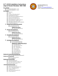
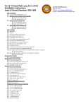
User's Guide DT1000, DT2000, & DT8000 Pinewood Derby Finish Line and Timer Software Version 4.0 (DT8000) Software Version 2.0 (DT1000 & DT2000) 12/31/2011 NewBold Products, Atlanta GA www.newboldproducts.com 2 1. Introduction Thank you for purchasing the DTX000, Pinewood Derby Timer. Whether you’re a Scout, Royal Ambassador, Awana, or in another group, we hope you find the DTX000 helpful in developing your cars and conducting your race events. This manual refers to the “Pinewood Derby” (PWD) race event. We realize that many groups have different names for the event, but for simplicity we will use what seems to be the predominant name. This manual provides information for three models: DT1000, DT2000, and DT8000. Features specific to a particular model are noted in the sections that follow. NewBold Products began designing and building PWD timers in 1996, initially a simple one-lane timer, primarily for developing fast cars. That first timer became a marketed product, the DT1000. The DT8000 was our second PWD timer and represents a dramatic increase in product capability and performance while maintaining the same affordability that became our trademark with the DT1000. NewBold Products believes that high quality and low cost is possible through using a standard configuration regardless of the application. Your DTX000 timer will fit any track from 1 to 8 lanes regardless of length or lane spacing and can be used on tracks of different groups without any modification. To accomplish this, the DTX000 automatically determines the track configuration and adjusts to provide the maximum information possible. A serial port connection interfaces to virtually any PC and does not require any custom software! The DTX000 is a software-driven device, making the basic system flexible and inexpensive. While control and display functions are software based, all critical timing operations are performed in hardware to ensure precision. FEATURES - Timing accuracy to resolution of 0.1 ms (.0001 sec) Maximum time of 9.9999 seconds 8 Digit Liquid Crystal Display (LCD) Provides elapsed time and finish order for 1 to 8 lanes (depending on model) Configurable for use on ANY track regardless of length or width PC Interface, connects to any PC serial port PC Interface can be used with virtually any PC and NO custom software is required PC can reset timer, by pressing space bar <SPACE> (PC sends 20h to DT8000) Single configuration regardless of number of lanes in use Automatically determines lanes in use and selects the correct operating mode Simple and easy to learn user interface ABOUT THIS MANUAL The DTX000 User’s Manual contains the information that you need to install and operate the system and to conduct your Pinewood Derby event. If you are reading this document on your computer, you can use the blue hyperlinks to jump between sections. You should read the entire manual to fully understand and properly use the DTX000. At a minimum you should read sections 2, 3, and 4. Section 2 provides installation information to guide you through installing the start switch, stop sensors and placing the DTX000 handheld unit. Section 3 provides a functional description of the DTX000 describing connections, LCD display, start switch, Personal Computer interface, and a description of each operational mode. 3 Section 4 describes how the user will use the DTX000 for each mode and specifics on how the unit interfaces to a PC. Section 5 is our Troubleshooting section. Section 6 describes warranty, return policies and ways to contact us. RECEIVING YOUR SHIPMENT Your order was carefully packed and inspected prior to shipment. Along with this manual, your order should contain at a minimum: DTX000 Handheld unit (DURACELL 9V battery installed) Starting Switch & cable (40 foot length standard) Stop Sensors & cables (10 foot length standard) - 1 stop sensor shipped standard with DT1000 - 2 stop sensors shipped standard with DT2000 - 3 stop sensors shipped standard with DT8000 Cable Ties Some orders may contain additional equipment such as Stop Sensors (for tracks with 4 or more lanes), Computer Interface cable, USB to Serial Port Adapter, AC adapter, Carrying Case and Race Management Software. Note that the Computer Interface cable is a standard serial port DB9 Male to DB9 Female cable with a “straight through” or 1:1 configuration, available from most computer and electronics stores. Race Management Software such as DerbyMaster and Grand Prix Race Manager is available to enhance the use of the DTX000’s computer interface. 2. Installation Procedure Tools Required To Install: Before you get started with your installation, you will need to gather a few hand tools and related items required to test and operate the DTX000. The required items are: 1) Hand-held Drill & 3/8 inch drill bit 2) Wire cutters or scissors 3) Light source (typically 1, 60-75W Incandescent Bulb for every 3-4 stop sensors) 4) Fine Tipped Punch or Nail (optional) The DTX000 timer, start switch, and stop sensors are used on the pinewood derby racetrack as shown in Figure 1. The incandescent light doesn’t need to be placed too close to the track, probably 3-6 feet above the track is sufficient depending on ambient light conditions. Installing the 9V Battery To install the 9V battery you will need to remove the back cover from the handheld unit. Remove the six machine screws that hold the two halves together. Remove the back cover and install the 9V battery into the black battery holder near the bottom of the circuit card. Replace the cover and install the six machine screws. Using the 9V Wall Adapter The wall adapter that NewBold Products sells is a 2.1mm plug, 9VDC output adapter with the center conductor having the Positive polarity. Warning: Using a wall adapter with the incorrect polarity will damage your timer making it inoperable. 4 Incandescent Light Source Starter Peg Start Lever w/ Switch Finish Line w/ Sensors Software Options - HyperT erminal (*free) - RaceVIEW - DerbyMaster Cable to Start Switch Cablesto Stop Sensors #1 - #8 Serial Cable DB9Fto DB9M DTX000 Timer Figure 1. Timer, Switch, and Sensors Installing the Stop Sensor(s) (see Figure 2) To begin your installation, decide where you will place the stop sensor(s) at the finish line. They should be located approximately 32 feet from the starting line and also as close to the centerline of each lane as possible. Note that not all tracks are 32 feet in length, but 32 feet is probably the most common. Regardless of length, it is important that each sensor be equal distance from the starting line to avoid errors in timing and finish order. Car's Guide Rail Stop Sensor Sensor Cab le Tr ack - Side Vi ew 3/8" Diam eter Drilled Hole Lane A Lane B Finish Line Tr ack - Top View Figure 2 – Sensor Installation The sensor diameter is 0.38”. Once you have measured and marked the locations for the stop sensors, use a fine tipped punch or nail to make a starting indention. This will help keep the drill bit well centered when you begin to drill. You should consider using a smaller drill-bit to make a “pilot” hole. This pilot hole will keep the larger drill bit more precisely on your center mark. If this is going to be a permanent installation you can glue each sensor in place using epoxy, a hot glue gun or other suitable glue. If you plan to use the DTX000 on multiple tracks you probably want to make the sensor installation more temporary, using a weak glue or tape. Also you may not need any glue at all if your sensors fit snugly into your drilled holes. Cable ties and cable holders are provided with your timer. You can position the cable holders on the bottom or sides of your track and use the adhesive back to attach them. The cable ties can then be used to bundle your wires together for a neater installation. The stop sensors are provided with 10-foot wire lengths, so the DTX000 timer should be located about 5-6 feet up from your finish line and several feet away from the track. Next you should plug in the sensors into the timer. You will see a set of nine pins at the top of the timer. The pins are 5 in two rows, with each pair lining up vertically. The switch pair is the first set of pins when looking at the timer as it is sitting on a table. The next pair is for the finish line sensor for Lane 1, and so on, up to Lane 8, if used. Important: The stop sensor has a polarity, therefore it will only operate when connected in one way. Connect the sensor to the timer so that the STRIPED wire or COPPER color wire is on the TOP wire (the wire closest to the front of the timer should have the stripe). Note: the switch connects to the first set of pins and the sensors are numbered 1-8 vertically after the switch. Installing the Start Switch (see Figure 3) Typically the starter’s lever is implemented in a variety of ways. The start switch can be mounted to the side of the track with screws, epoxy, hot glue etc. The exact implementation is dependent on your particular track design. The start switch needs to be installed so that the switch opens when the starting lever of your track moves to start the race. Also be sure to move the lever quickly so that cars are not leaning on the Starting Peg as it moves forward. If you impede the car’s progress with the Starting Peg, the elapsed times can vary from race to race, dependent on the speed at which the lever is moved. The start switch is supplied with a 40-foot cable length. The start switch should be closed for at least 0.5 seconds between races. Starting Peg Start Switch Closed Prior to Start - Install using, wood screws,epoxy, etc. - may require a small standoff block of wood to position switch under lever Starter's Lever Figure 3 – Start Switch Installation Routing Cables You can route your cables however you think is best. We suggest using the supplied cable ties and cable mounts to attach the cables to the bottom of your track and routing them to the DTX000 display in a bundle if possible. 3. Functional Description Unit Display, Interfaces and Controls: The DTX000 system is comprised of the handheld unit, start switch, and stop sensor(s). The handheld unit has nine areas of interest. These items are: 8 Digit LCD – displays finish order and/or elapsed time depending upon mode. Green LED – when on, indicates that the DTX000 is timing a race. Reset Button – used to clear Self-Test displays and to reset prior to a new race. Power Switch – turns on power to DTX000. Low Battery LED – Red LED above power switch turns on when battery is low. (Version 2 hardware and later) 6) AC adapter connection -allows use of a 9V wall adapter in place of 9V battery. (Version 2 hardware and later) 7) 18-pin Header – connections for start switch and stop sensors 1-8. 1) 2) 3) 4) 5) 6 8) DB9 Female – connection for serial port computer interface, mates with DB9 Male connector. 9) Video Out – connection for DerbyTV to connect to television's video input Turning on the DTX000, Self-Test and Operating Modes: 1. Turn the power on by moving the “Power” switch up. 2. The handheld unit performs a Self-Test. It turns on all segments of the LCD and turns on the green LED to allow the user a check of all the displays. 3. Press the RESET button. At this point, the DTX000 automatically determines how many stop sensors are connected and which operating mode you will be using. IMPORTANT NOTE: A sensor is only “found” present for a given lane if adequate light is present on the sensor for that lane. The LCD will display the number of lanes found i.e. “ 3 LANES”. If no lanes are found, the LCD will display “- - - - - - - -“. This indicates the error situation where no stop sensors are found present. If this error is displayed, the user should check the stop sensor connections and light sources. Make sure all sensors are plugged into the unit and make sure all lights are placed closely above the sensors. Then turn the power off and back on using the Power switch. Make sure the correct number of lanes is displayed before continuing. 4. Once the number of lanes is found and is correct, the user should press RESET. 5. After pressing RESET a second time, the LCD displays on which lanes sensors were found. A dash is illuminated for each sensor found. For example if you have a 6 lane track and only 5 sensors are found the LCD might show the following “ - - - - -“ to indicate that sensors were found connected to inputs for lanes 1, 2, 3, 5, and 6. This allows the operator to quickly identify a problem connection. [DT2000 models have a maximum of two lanes, and DT1000 models use a single lane] 6. Press RESET again to enter timing mode. The DTX000 will enter one of three timing modes, based on the number of lanes found present: Mode 1 -- 1 Lane is Present (DT1000, DT2000 & DT8000) Mode 2 -- 2 Lanes are Present (DT2000 & DT8000) Mode 3 -- 3 to 8 Lanes are Present (DT8000 only) When the DTX000 enters timing mode, the LCD will be blank and the green LED will be off. Mode 1: (all DTX000 models) In Mode 1, the DTX000 times a single lane. This mode can be used for car development prior to race events and for conducting single-lane time trials. For this mode to work, the stop sensor must be connected to finish line sensor input #1 (second set of pins) and all other sensor inputs should be left open. After turning the power on, the user should press RESET to clear the Self-test display. After this RESET, the LCD will display “ 1 LANE” to indicate that the stop sensor was found on for Lane #1. Press RESET again to enter the timing mode. The timing starts when the start switch opens and will stop when the car passes over the stop sensor. The LCD will then display the elapsed time with a resolution of 0.1 ms. An example time display on the LCD is: 2.5135 7 This time is also transmitted by the DTX000 serial port connected to a computer. The computer can receive the information via a serial port or USB port to receive the information. The time is sent to the computer using 7-bit ASCII characters that can be interpreted by any terminal type program such as the “Hyper Terminal” program, which can be available on many Windows machines. You can also choose to run a race management software program to manage your race. Refer to Section 4 for details on configuring your PC for communicating with the DTX000. The data sent from the DTX000 to the PC is similar to the following: (DT1000 shown) DT1000 NewBold Products 2.5315 3.1022 : 2.9673 Most recent time Press RESET on the timer or the <SPACE> bar on your computer to clear the LCD and begin a new race. Mode 2: (DT2000 & DT8000 models) The DTX000 times two lanes when in Mode 2. The DTX000 automatically enters this mode when stop sensors are found connected to sensor inputs #1 and 2 (second and third set of pins) and all other sensor inputs are left open. After turning the power on, the user should press RESET to clear the Self-test display. After this RESET, the LCD will display “2 LANES” to indicate that two stop sensors were found. After pressing RESET again, the LCD will display two dashes in the “1 st “ and “2nd” locations. After pressing RESET again, the DTX000 will enter the timing mode. Timing starts when the start switch opens and continues until both cars have crossed the finish line (passing over the stop sensors). The LCD will first display the winning car’s lane number and the elapsed time for that car. For the first place car, the lane number will be shown in the far left digit directly above the label that reads st “1 ”. For example if the car in lane 2 finishes first, the LCD display might read 2 2.5135 This time is also transmitted by the DTX000 serial port connected to a computer. The computer can receive the information via a serial port or USB port to receive the information. The time is sent to the computer using 7-bit ASCII characters that can be interpreted by any terminal type program such as the “Hyper Terminal” program, which can be available on many Windows machines. You can also choose to run a race management software program to manage your race. Refer to Section 4 for details on configuring your PC for communicating with the DTX000. The data sent from the DTX000 to the PC will be similar to the following where the data is provided as 1st Place Lane, 1st Place Time, 2 nd Place Lane, 2nd Place Time. Each new race that is run will have a new set of times incrementally displayed on the computer screen. The times displayed on the bottom row are the most recent results. (DT2000 shown) DT2000 NewBold Products 1 2.5455 2 2.9831 1 2.6790 2 3.1288 : 2 2.8820 1 3.5109 8 After displaying the winning lane # and elapsed time, the user should press either the RESET button on the timer or the <SPACE> bar on the computer, to display the 2 nd place lane number and elapsed time. The second place lane number is displayed on the LCD in the second digit of the display, directly above the label that reads “2 nd”. Pressing RESET or <SPACE> bar again will clear the LCD and the timer will be ready to time the next race. Mode 3: (DT8000 only) Mode 3 is for installations where 3 or more lanes are to be used, up to a maximum of 8 lanes. The DT8000 automatically enters this mode when stop sensors are connected to 3 or more sensor inputs. All unused sensor inputs should be left open. After turning the power on, the user should press RESET to clear the Self-test display. After this RESET, the LCD will display “X LANES” to indicate the number of lanes that have been identified as connected, where X could be from 3 to 8. After pressing RESET again, the LCD will display a dash in the location where each sensor was found. After pressing RESET again, the DT8000 will enter the timing mode. Timing starts when the start switch opens and continues until all cars have crossed the finish line (passing over the stop sensors) or the elapsed time is > 9.9999 seconds. Once the last car has finished, the LCD will display the finishing order for all cars. The LCD data is formatted to display from left to right: 1st Place Lane, 2nd Place Lane, etc. For example if 4 cars are racing and lane 3 finishes first followed by 4, 1, and 2, then the LCD will read “ 3 4 1 2 “. Pressing RESET on the timer or <SPACE> bar on the computer will clear the LCD and the timer will be ready to time the next race. The DT8000 serial port transmits the finish order and elapsed times for all cars. The data sent by the serial port is formatted as 7-bit ASCII characters that can be interpreted by any terminal type program such as Windows 95’s “Hyper Terminal”. Refer to Section 4 for details on configuring your PC for communicating with the DT8000. The data sent from the DT8000 to the PC will be similar to the following, where the data is provided as 1st Place Lane, 1st Place Time, 2nd Place Lane, 2nd Place Time etc. The following illustrates the data that might be received if four lanes are in use. DT8000 NewBold Products 1 2.5455 2 2.9831 3 3.7745 4 3.8224 1 2.6790 3 3.1288 2 3.2092 4 3.5644 : 3 2.8820 1 3.5109 4 3.5134 2 3.6202 4. Operation General As mentioned in Section 3, at power-up the DTX000 will turn-on the LED and all segments of the 8-digit LCD. The user should press the “RESET” button to clear this initial state. The DTX000 then determines the number of stop sensors connected to the timer. Once the software makes this determination an operational mode is set: Mode 1, Mode 2, Mode 3 as described above. Once set, this mode cannot be changed except by powering down, removing or connecting additional sensors and reapplying the DTX000’s power. If you plan to use the computer interface, you should configure the computer’s terminal program and connect the DTX000 to the PC prior to applying power to the DTX000. There is no problem with making this connection after power-up, but your PC will miss the initial information sent from the DTX000. Refer to the end of this section for information on how to configure your terminal program. 9 Mode 1 Operation (DT1000, DT2000 & DT8000) In Mode 1, the green LED will turn on once the Start Switch opens and turns off when the car crosses the finish line. After the car finishes the DTX000’s LCD will display the elapsed time and the PC if connected will also display the elapsed time. The LCD will hold this time indefinitely until the user presses the “RESET” button or the <SPACE> bar on the computer. After the user presses “RESET” the DTX000 will clear the LCD and wait for the Start Switch to move. The start switch must be closed for .5 seconds before opening. This cycle repeats continuously. Mode 2 Operation (DT2000 & DT8000) In Mode 2, the green LED will turn on once the Start Switch opens and turns off after both cars cross the finish line for lanes 1 and 2. After both cars have finished, the DTX000’s LCD will display the winning car’s lane number and the elapsed time for that lane. After the user presses “RESET” the LCD will display the second place car’s lane number and elapsed time. The PC if connected will display the finish order and elapsed times for both lanes. The LCD will hold with this information indefinitely until the user presses the “RESET” button or the <SPACE> bar on the computer. After the user presses “RESET” a second time, the DTX000 will clear the LCD and wait for the Start Switch to move. The start switch must be closed for .5 seconds before opening. This cycle repeats continuously. Mode 3 Operation (DT8000 only) In Mode 3, the green LED will turn on once the Start Switch opens and turns off after all cars have crossed the finish line. In this mode, the number of lanes in use can be any number from 3 to 8 and the stop sensors can be connected to any position at the 18 pin header. For example the user can have 4 lanes connected to DTX000 connections for lanes 3, 4, and 6, and 8. The DTX000 will wait for these four lanes to finish. Important: Only connect stop sensors for those lanes in use. Having additional sensors connected will cause the DTX000 to wait for the additional lane to finish as well (or timeout after 9.9999 seconds) After all cars have finished, the DT8000’s LCD will display the finishing order by lane number. The PC if connected will display the finish order and elapsed times for all lanes. The LCD will hold with this information indefinitely until the user presses the “RESET” button or the <SPACE> bar on the computer. After the user presses “RESET” the DT8000 will clear the LCD and wait for the Start Switch to move. The start switch must be closed for .5 seconds before opening. This cycle repeats continuously. Connecting Your Computer: If you would like to display and perhaps save the race results, you can see this information by using the DTX000 serial port. It will send the finish order and elapsed times for all cars to your computer. The timer has a serial port connector on the end of the timer. You may connect your computer to the timer in one of two ways: either use a serial port computer interface cable (DB9 male to female) or use a USB to serial interface adapter along with the serial port cable. This will then allow you to connect from your computer's USB port to the serial port on the timer. We have both of these products in stock if you need to add them to your supplies. You may also purchase these items at a computer supply store. If you choose to use a USB port, you will receive a driver CD to install on your computer. This driver must be installed first before you connect the cable to the timer. If you lose the CD and need a replacement for the driver (and if you purchased it from us), you may download the driver from our website under the Questions section at www.newboldproducts.com. You may also find information regarding USB setup under the Frequently Asked Questions tab on our website. 1 0 Configuring Your Computer’s Terminal Program (DT1000, DT2000 & DT8000) The DTX000 sends data to your computer at 1200 baud, with 7 data bits, no parity, and 2 stop bits. You should also turn flow control “OFF”. Many Windows OS computers have the terminal program “Hyper Terminal” already installed. If you can not find this on your computer, you may download it online. This program can be sometimes be found under <Start>, <Programs>, <Accessories>, <Hyper Terminal>. Once you have started this program, go to <File>, <New Connection>. The program will prompt you for a name, you could call the session “DTX000” or whatever you prefer. After giving a name, you will have a phone number dialog box. From this dialog box edit the “Connect Using” box to say “Direct to Comx”. Where Comx is Com1, Com2, etc. The serial port number varies on different machines. After entering your Com port and <OK>, you will see a Comx Properties dialog box. At this box enter the connection properties as Bits per second = 1200, Data bits = 7, Parity = none, Stop bits = 2, Flow control = none. Once you have setup your session you can save it as “DTX000” or another name and each time you use the DTX000 you can startup Hyper Terminal and simply load this file. If you are using another communications program such as ProComm you can make a similar setup file, only the steps will vary slightly. Note on Font sizes: When using the Hyper Terminal program (or others) you can change the font size as required. For the best results (especially for large group displays as in Section 5) you may want to adjust your font so that your results for a single race fill the majority of the screen’s width. This works particularly well for setups with less than 5 lanes. Displaying Your Results to a Large Group You may choose to display the results of your race to your group so that everyone can see. There are two methods that can be used to do this: Purchase DerbyTV – you will need to send us your timer module to have a 2 nd circuit board installed; after installation, you may hook up the timer directly into a TV video input to receive a simple display of the results of each race. You may see sample screen shots of DerbyTV online at www.newboldproducts.com. Look in the Products section. Use a large screen projector and project the images from your computer. You can display either the Hyper Terminal screen or the race management software you are using. 5. Troubleshooting Cars are not stopping timer. Check the lighting. Adjust the lighting away from the timer, so that the sensors are not found when timer is switched on. Then move the lighting closer to the track in 6” or 12” increments; continue turning the timer on and pressing reset to see if all lanes are recognized. Stop moving the light closer once all lanes are found. Minimize unnecessary ambient lighting if this seems to be a problem. Flash photography is not a problem with the DTX000. The DTX000 is not designed to work outside in sunlight. Stop sensors are not found. Verify that enough light is present over the sensor (60 Watts for every 3-4 lanes). Make sure you are using an incandescent type of light – stay away from using halogen and flourescent lights. Verify that the sensors are plugged into the handheld unit with the correct polarity – copper facing up, starting on the 2 nd set of pins. Timing or start/stop seem erratic. If you have very low times such as 0.2000 seconds, this indicates your light source is too low. Move the light source 3-6 inches closer to the stop sensors 1 1 and retest. Test using mode 1 or mode 2 (1 or 2 lanes only), to verify the elapsed time is accurate. Timer does not appear to stop. You may have too much light over the sensor. Back the light off some and try again. See section above on “cars not stopping the timer” for how to adjust the lighting. Serial interface not sending data to computer. 1) Verify that the cable is well connected to both the timer and computer. 2) Confirm that the serial port DB9 cable is a “straight through” or 1:1 cable (this means that pin 2 connects to pin 2, pin 3 to pin 3 etc.) You can use a voltmeter to do this. 3) Make sure that the serial port is configured properly if using Hyperterminal or Procomm. See Section 4 above. 4) Verify that the connector you are using on your computer is really the Comm port you think it is. To test this: Disconnect the computer interface cable at the timer end, short pins 2 and 3 together and using Hyperterminal, type information on the keyboard, this info should be echoed back to your computer’s monitor if you have selected the correct Comm port. 5) Verify that your PC is not running any background applications that may be interfering with the Comm port, such as Palm Desktop applications, phones, ipod, etc. Under Win 95/98 the right side of the task bar shows programs that are resident in memory, some of these may need to be closed to allow your PC to talk to the Comm port. 6) If you are using race management software, you must completely close out Hyper Terminal before opening the race software. They can not both be running at the same time. 7) If you are using a USB adapter, you must have the driver installed on your computer. If you purchased the adapter from us, you may check www.newboldproducts.com, under Questions for a link to the download the USB driver for the USB to serial adapter. 8) If you have installed the USB driver, check in the Windows Hardware Device Manager to see if the driver is listed. It will assign it a Comm Port number. Use this Comm Port number in Hyper Terminal or in your race management software program. DerbyMaster Problems: Please refer to in-program help documentation found when running DerbyMaster or contact Enterprising Ideas at 1 (972) 394-0381 or on the web at www.derbymaster.com. Grand Prix Race Manager Problems: Please refer to the in-program help documentation found when running Grand Prix Race Manager or contact Lisano Enterprises at 1 (303) 362-1300 or on the web at http://grandprix-software-central.com/. 6. Contacting NewBold Products, Warranty and Return Policies We would very much like to HEAR from YOU regarding the DTX000 and how you used it for your car preparations and race event. If you send us pictures of your event, we will put them online! Thanks for your input! Send us email: [email protected] Call us: 1(866) NEW-BOLD or (678) 812-4585 Fax: (815) 301-3426 Mail: NewBold Products, 1200 Oakhaven Drive, Roswell, GA 30075 6- Year Parts & Labor Warranty NewBold Products provides a six-year warranty for all equipment, starting from date of shipment and covering parts and labor. If you believe your equipment needs warranty repair contact us to 1 2 let us know the nature of the problem and so that we can resolve it over the phone if possible. If the problem cannot be corrected over the phone we will request the equipment be returned to us for repair. The customer is responsible for shipping the product back to NewBold Products. NewBold Products will repair and return the equipment via Priority Mail or FedEx Ground. Faster shipping is available at actual cost. Warranty repairs are not applicable for modified or damaged equipment. 90 Day Return Policy If for any reason, you are not satisfied with your equipment purchase, you may return it within 90 days of purchase for a full refund (excluding shipping charges). Once equipment is received and inspected we will issue a refund. This return policy does not apply to any modified or damaged equipment. 1 3