1
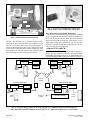
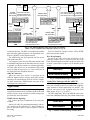
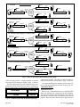
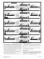
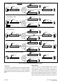
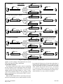
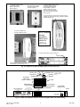
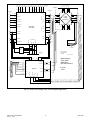
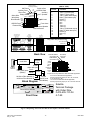
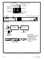
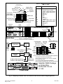
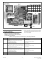
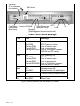
DPS Telecom
User Manual
FDO 1000 Order-Wire (Packages*)
Fig. 1 - FDO 1000 Order-Wire Terminal with Adaptive PCM card interfaces 24 Kbit channel.
Call Buzzer
A buzzer in the order-wire announces incoming calls.
An optional buzzer can be installed in the phone.
External speaker
The FDO 1000 includes a 2-watt speaker amplifier that
can be used to drive an external eight ohm speaker. A
paging feature can be activated from any calling station to
allow the desired party's name to be announced over the
speaker.
Passive Bridge, Optional Active Bridge.
The FDO 1000 is facility-ready, with a built-in 4-Way
passive bridge and level matching pads for +7 / -16 dBm
channel levels. The bridge can also be bypassed for direct
interface at the order-wire's active VF ports. An accessory active bridge can be installed on the order-wire's
P.C. board for matching levels other than +7/-16 dBm.
Network Control
In privacy modes, the FDO 1000 uses automatically
generated DTMF tones to control access to the order-wire
FDO 1000 Order-Wire Description
With DPS' FDO 1000 Order-Wire terminal, your analog or digital network can become your own private
phone system, with links to the public telephone network.
The order-wire is an economical party-line system that
requires no central switching. An order-wire terminal and
telephone are located at each facility in your network.
The order-wire system is simple to operate and can significantly reduce your voice communications costs.
DTMF Selective Signaling
The DPS FDO Order-Wire uses the on-board microprocessor to synthesize and decode DTMF signaling
tones. The FDO can be programmed for automatic privacy, manual privacy, no privacy and hoot-n-holler operating modes.
Digital Interface
The FDO 1000 order-wire can be equipped with an
Adaptive PCM (ADPCM) digital interface card in the expansion card slot. This interfaces the order-wire to a 24
Kbit port on DPS' DVF-64 digital VF interface card.
LED Indicators
Front panel LEDs indicate order-wire off-hook, incoming call ringing and channel busy. Front panel test points
and level controls are provided for calibration.
Addressing
The Order-Wire responds to one, two or three digit addressing. Leading zeroes in the address will set it for one
or two digits. Rotary switches on the P.C. Board allow the
address to be easily set. The station address is posted on
the front panel with stick-on labels (labels are included).
Four-Wire Phone
Voice communications and out-dialing occur at a
4-wire telephone, mounted near the order-wire.
Table of Contents
Description . . . . . . . . . . . . . . . . . . . . . . . . . . . . . . . . . . . 1
Adaptive PCM (ADPCM) . . . . . . . . . . . . . . . . . . . 2
Applications . . . . . . . . . . . . . . . . . . . . . . . . . . . . . . . . . . 3
Applications with the ADPCM . . . . . . . . . . . . . . . 3
Operation Modes . . . . . . . . . . . . . . . . . . . . . . . . . . 4
Shipping List . . . . . . . . . . . . . . . . . . . . . . . . . . . . . . . . . 8
Installation . . . . . . . . . . . . . . . . . . . . . . . . . . . . . . . . . . . 8
Reference Figures . . . . . . . . . . . . . . . . . . . . . . . . . . . . . 8
Test and Acceptance . . . . . . . . . . . . . . . . . . . . . . . . . . 22
Change Notice
2-8-99: Added ADPCM LEDs info.
3-1-99: Converted to user manual, general corrections,
clarified term./rptr. switch, added Table J.
5-17-99: Added center-fold, model chart and glossary.
FDO 1000-11A-0V/ADPCM
May 17, 1999
Specifications . . . . . . . . . . . . . . . . . . . . . . . . . . . . . . . . 24
Options and Model Numbers . . . . . . . . . . . . . . . . . . . 24
* See Table J on page 24 for a listing of packages that
use the FDO 1000 Order-Wire.
1
UM110339
Trimline Type
Wall Phone
*4-1/2" square box
can mount on
rack side rail
or any flat surface
Speaker with
Level Control*
2 Wires
Direct
Port
4-Wire
VF Line
4 Wires
4 Wires
Fig. 3 - Accessories for Order-Wire include active
4w/4w bridge, 4-wire DTMF phone and speaker.
FDO-1000 Order-Wire Terminal
(shown with ADPCM digital interface card in expansion slot)
Wire-Wrap and Connectorized Back Panel
All network, power and ancillary connections are made
at wire-wrap blocks and connectors on the back panel. An
RJ-12 jack is provided for the phone and screw-terminal
barriers are provided for the power (office battery). voice
input/output, bridge port connections, fuse alarm, external buzzer, speaker and M lead connections are all provided on a 60 pin wire-wrap block.
Fig. 2 - Order-wire packages include external speaker,
phone, ADPCM and rack-mount housing.
network. An off-hook tone is generated when a caller
picks up the phone, which causes other stations on the
network to assume a busy state. If any other phone is
picked up during the busy state, a busy signal will sound
in the earpiece. Busied stations remain in that state until
their station code is dialed from the caller's phone or until
the caller hangs up, generating an on-hook tone.
Adaptive PCM (ADPCM)
DPS’ Adaptive PCM (ADPCM) provides a digital interface for voice frequency signals in the 300 to 4KHz
bandwidth, particularly order-wire. It digitizes the voice
to a 24 Kbit channel that is passed on to a DVF-64 card in
FDO1000 Order-Wire
Order-Wire
Electronics
FDO1000 Order-Wire
ADPCM
ADPCM
DVF-64
DVF-64
Order-Wire
Electronics
Speaker
Speaker
4-Wire
Phone
4-Wire
Phone
Digital
Network
FDO1000 Order-Wire
Order-Wire
Electronics
FDO1000 Order-Wire
ADPCM
ADPCM
DVF-64
DVF-64
Speaker
Speaker
4-Wire
Phone
Order-Wire
Electronics
POTS Line
to PSTN
FDO 3000 Off-Net
4-Wire
Phone
Fig. 4 - A typical analog order-wire network provides voice communications between telecom sites
and to the Public Switched Telephone Network (PSTN) via a Plain-Old Telephone Service (POTS) line.
UM110339
2
FDO 1000-11A-0V/ADPCM
May 17, 1999
OW Chan.
OLS
or OT
OA
A
Terminal
FDO 1000 Order-Wire
Order-Wire FDO 3000 Off-Net eq/w
with Off-Net DVF-64 Expansion Card
Off-net
Phone
Line
A-Chan.
OA
OA
B
OLS
or OT
OW Chan.
Terminal
FDO 1000 Order-Wire
FDO 3000 Off-Net eq/w Order-Wire
DVF-64 Expansion Card with Off-Net
Satellite TABS
with Order-Wire
FDO 1000 Order-Wire
KDA 864-TABS eq/w
DVF-64 Expansion Card
Front Door
RS422 TABS
(1200 Baud)
TABS
A
TABS
A
B
Satellite TABS
with Order-Wire
NTP
TABS
TABS
B
Back Door
Off-net
Phone
Line
RS422 TABS
(1200 Baud)
B-Chan.
Satellite TABS
with Order-Wire
FDO 1000 Order-Wire
KDA 864-TABS eq/w
DVF-64 Expansion Card
FDO 1000 Order-Wire
KDA 864-TABS eq/w
DVF-64 Expansion Card
NTP
Fig. 5 - The ADPCM digitizes order-wire to put it on SONET.
NOTE: A more complete network diagram is shown in Fig. 20.
an adjacent housing. The DVF-64 assembles the 24 Kbit
data with other signals and places it on the 64 Kbit overhead on a SONET or other digital network.
The ADPCM fits into the expansion card slot on the
FDO 1000 Order-Wire.
Two separate circuits are included on the module, with
a switchable bridging network that allows the two circuits
to perform in a either a terminal or a repeater application.
An FDO 3000 Off-Net can be connected to the second
circuit to adapt the order-wire to a 2-wire POTS line in
the Public Switched Telephone Network.
ADPCM Connectors
When the order-wire chassis is equipped for an
ADPCM digital interface card, the back panel includes
connectors for interfacing the DVF-64 card in a companion shelf. Access to the ADPCM order-wire ports is provided at the wire-wrap block.
Each site should be equipped with a 4-Wire DTMF
phone and external speaker.
Wire-Wrap Jumpers
To utilize the order-wire's four-way bridge or the
ADPCM, jumpers must be installed at the wire-wrap
block. When the application details are known at the time
an order is placed, these jumpers will be installed at the
factory.
Order-Wire
KDA network element
DVF-64
Fig. 6 -Satellite KDA package w/Order-Wire.
Order-Wire Packages with the ADPCM
The FDO 1000 Order-Wire with ADPCM can be combined with a DPS KDA 864-E2A or KDA 864-TABS network element for alarm applications via SONET. The
DVF-64 card resides in the expansion card slot of the
KDA chassis. (Figs. 5, 6, 23 and 27)
The FDO 1000 Order-Wire with ADPCM can be combined with a DPS KDA housing with a blank module and
Applications
The FDO 1000 is available in application packages that
include KDA alarm network elements and the FDO 3000
Off-Net. Details on the currently available packages are
provided later in this document.
DTMF Selective Signaling
Fig. 2 shows the basic components of the order-wire
terminal.
Station call codes are programmed manually with rotary switches on the order-wire P.C. board. Number labels are provided to place on the front panel to indicate
the setting.
FDO 1000-11A-0V/ADPCM
May 17, 1999
ADPCM
Order-Wire
ADPCM
Blank Module
DVF-64
Fig. 7 - Satellite Terminal package w/Order-Wire.
3
UM110339
Automatic Privacy
1. Off Hook
Busy
222
Muted
Dial Tone
Busy Tone
Muted
Off Hook
111
Off Hook
Tone (#)
Muted
Busy
Voice
Facility
333
Muted
Busy
444
2. Dial Station Code
DTMF Tones
(side tone)
Muted
Busy
Busy Tone
222
Muted
Off Hook
111
333
Voice
Facility
Dial Code
Muted
Buzzer
Ring
333
Muted
Busy
444
3 3 3
DTMF Tones
(side tone)
Busy
222
Muted
Off Hook
111
8333
Voice
Facility
Dial Code
Joe
Smith!
Ring
333
Muted
Busy
444
8 3 3 3
3. Call Answered
Off hook tone
Talk
Busy Tone
Muted
2a. Alternate dial w/page (8 + station code)
Muted
Busy Tone
Muted
Off Hook
Off Hook Tone (#)
111
Busy
222
Voice
Facility
Muted
Off Hook
Talk
333
Muted
Busy
444
4. Call Terminated (system normal)
Unmuted
111
Unmuted
222
On Hook
Tone (*)
On Hook
Tone (*)
Voice
Facility
Unmuted
333
Unmuted
444
Fig. 9 - Order of operation in the automatic privacy mode.
connection to SONET. The DVF-64 card fits in the expansion card slot of the off-net chassis. (Figs. 5, 8 and 22)
An expansion package is available to add an order-wire
to a site with an existing KDA network element. (Fig. 25)
a DVF-64 card to make a “satellite terminal” to provide
voice and E2A/VF interface to SONET. (Figs. 7. and 25).
The FDO 1000 Order-Wire with ADPCM can be combined with an FDO 3000 Off-Net to make a "terminal order-wire with off-net" for interfacing voice and a PSTN
Order-Wire
Off-Net
Operation Modes
Automatic Privacy
Refer to Fig. 9. In the automatic privacy mode the FDO
order-wire performs like a normal private line telephone.
The caller hears dial tone when the phone is first taken off
hook and an “off-hook” tone is broadcast to busy out the
network. When the caller dials the three-digit code for a
ADPCM
DVF-64
Fig. 8 - Terminal Order-Wire With Off-Net package.
UM110339
4
FDO 1000-11A-0V/ADPCM
May 17, 1999
Manual Privacy
1. Off Hook
222
Muted
Dial Tone
Unmuted
Off Hook
Voice
Facility
111
Unmuted
333
Unmuted
444
2. Dial Station Code
DTMF Tones
(side tone)
Unmuted
222
Muted
Off Hook
111
3 3 3
333
Voice
Facility
333
Unmuted
444
Dial Code
3. Call Answered
Talk
Unmuted
Buzzer
Ring
Unmuted
222
Muted
Off Hook
Talk
111
Voice
Facility
Muted
Off Hook
Talk
Off Hook
Talk
333
Unmuted
444
3. Invoking Privacy
Press #
Muted
Busy
Busy Tone
222
Muted
Off Hook
#
111
Voice
Facility
#
Muted
333
Muted
Busy
444
4. Call Terminated (system normal)
Unmuted
111
Unmuted
222
On Hook
Tone (*)
On Hook
Tone (*)
Voice
Facility
Unmuted
333
Unmuted
444
Fig. 10 - Order of operation in the manual privacy mode.
The busy state may be manually cleared by pressing the
“*” button. It can be restored by pressing the “#” button.
Other parties can be added to the conversation at any
time.
An “all call” code rings all stations. Unanswered stations will time out in 90 seconds.
Manual Privacy
Refer to Fig. 10. The manual privacy mode works like
the automatic privacy mode, except that the caller must
press the “#” key to establish the busy state. It is released
by dialing a “*” or by hanging up the phone.
station, the buzzer at that station sounds and the caller
hears a ring-back tone. When the called party answers,
the ring-back and buzzer are silenced and conversation
may proceed. During the conversation all other stations
will hear a busy signal in the handset and all monitor
speakers are muted. Either party hanging up generates an
“on-hook” tone to clear the busy state.
In this mode the calling party may page the desired
party over the called station's speaker by dialing “8” prior
to entering the three-digit station code.
NOTE: Avoid using station codes starting with “8.”
FDO 1000-11A-0V/ADPCM
May 17, 1999
5
UM110339
No Privacy
1. Off Hook
Unmuted
222
Muted
Dial Tone
Off Hook
Voice
Facility
111
Unmuted
333
Unmuted
444
2. Dial Station Code
DTMF Tones
(side tone)
222
Muted
Off Hook
111
3 3 3
Unmuted
333
Voice
Facility
Dial Code
333
Unmuted
444
3. Call Answered
Talk
Unmuted
Buzzer
Ring
Unmuted
222
Muted
Off Hook
111
Talk
Muted
Talk
Voice
Facility
Off Hook
Talk
333
Unmuted
444
4. Group Conversation
Talk
Muted
Off Hook
Talk
222
Muted
Off Hook
111
NOTE: Station code does not
have to be dialed to enter conversation.
Muted
Voice
Facility
Off Hook
Talk
333
Unmuted
444
5. Call Terminated (system normal)
222
Unmuted
111
Unmuted
Voice
Facility
Unmuted
333
Unmuted
444
Fig. 11 - Order of operation in the no privacy mode.
Hoot-n-Holler
Refer to Fig. 12. A 4-wire telephone and an external
speaker can turn the FDO 1000 into a classic
“hoot-n-holler” order-wire. The speaker should be located where it can be heard by all parties at a facility. The
phone is used to announce the desired party over the monitor speakers. When the person answers, the speaker is
muted. All other sites continue to monitor the order-wire
No Privacy
Refer to Fig. 11. In the no privacy mode monitor speakers remain on when the system is in use and any station
may get on the system at any time. A station's monitor
speaker mutes only when the station phone is taken off
hook.
UM110339
6
FDO 1000-11A-0V/ADPCM
May 17, 1999
1. Off Hook
Hoot-n-Holler
Unmuted
Muted
Unmuted
Off Hook
Voice
Facility
Unmuted
2. Call name of party or station
Hey, Joe!
Hey, Joe!
222
Muted
Off Hook
Voice
Facility
111
Hey, Joe!
333
Hey, Joe!
444
3. Call Answered
Talk
Unmuted
222
Muted
Off Hook
111
Talk
Muted
Talk
Voice
Facility
Off Hook
Talk
333
Unmuted
444
4. Group Conversation
Talk
Muted
Off Hook
222
Muted
Off Hook
111
Voice
Facility
Talk
NOTE: Station code does not have
to be dialed to enter conversation.
Muted
Off Hook
Talk
333
Unmuted
444
5. Call Terminated (system normal)
222
Unmuted
111
Unmuted
Voice
Facility
Unmuted
333
Unmuted
444
Fig. 12 - Order of operation in the hoot-n-holler mode.
channel over the speakers. This application can use the
FDO-1301 phone and FDO-1200 speaker.
On/Off Hook Function
The factory default uses # and * tones for controlling
privacy functions. In cases where these tones are already
in use for other functions, switch SW5.3 can be set ON to
change control to the fourth column “A” and “C” tones.
(The fourth column buttons are not provided on the
phone, so manual privacy will not work if SW5.3 is ON.)
Off-Net Function
When an FDO 3000 Off-Net is used in the order-wire
network, the automatic privacy mode should be used for
FDO 1000-11A-0V/ADPCM
May 17, 1999
best control of off-net access. In the other modes there is
limited control. With manual privacy, you must press # to
lock out an outside call and * to disconnect an outside
caller. (NOTE: If an outside caller presses *, the call will
be terminated.) With no privacy and hoot-n-holler
modes, an outside call can interrupt an on-going conversation and there is no way to force a disconnect.
7
UM110339
NOTE: Speaker ground (SG)
is at -Batt. potential.
Do not ground it to
frame or other equipment.
1 2 3 4 5 6 7 8 9 10
Shipping List
¤
FDO 1000 Order Wire card
¤
Shelf
¤
Mounting Hardware
¤
Fuses
¤
Operation Guide
¤
Telephone
¤
Speaker
¤
ADPCM Card
¤
Interconnecting cables
A
B
C
D
E
F
C1
SG
C1
9E
9F
11. Apply station code numbers to front panel per
Fig. 17.
12. Set DIP switch for operating mode per Fig. 17.
(Factory default is "automatic privacy.")
13. Set speaker trim pot per Fig. 17.
14. Re-install P.C. board in housing.
15. Remove ADPCM card from shelf.
16. Check switch settings per Fig. 28.
(Factory default is "mid-point repeater.")
17. Re-install ADPCM card in housing.
18. Insert fuses at order-wire and ADPCM front panels.
19. Go to Test and Acceptance on page 18.
20. Installation is complete.
Table A - Dial Code Assignments
1. Unpack the order-wire and all accessories.
2. Install mounting ears for 23" or 19" rack. Position
as required per Fig. 13.
19" or 23" Rack/
5" Projection
19" or 23" Rack/
Flush Front
19" or 23" Rack/
5-1/2" Projection
19" or 23" Rack/
1/2" Projection
SIDE VIEW
REAR
Fig. 13 - Position mounting ears for desired projection.
3. Mount the order-wire terminal in a rack.
4. If a speaker is included, mount the external speaker
and connect to wire wrap block C1 per Fig. 14.
5. If a phone is included, mount the phone per Fig. 15.
Connect to RJ-12 jack on the back of the order-wire.
5. Make sure the fuse is removed from the front
panels of both the order-wire and the ADPCM.
6. Remove P.C. board from housing.
7. Connect all inputs and outputs per Fig. 16.
8. If passive bridge is used, connect jumpers at C1 on
the rear of the chassis per Fig. 16.
NOTE: If the application was known at the time of the
order, these jumpers will be factory installed.
9. Connect power per Fig. 16.
10. Set station number on rotary switches per Fig. 17.
Use leading zeroes to set for 1 or 2 digit coding. Refer
to Table A for code assignments.
UM110339
To FDO 1000
Order-Wire terminal
Fig. 14 - Connecting the FDO 1200 Speaker.
Installation
NOTE: Use wide ears for 23"
External Speaker
SPKR
Code
Assignment
000 thru 009*
010 thru 099*
100 thru 799;
900 thru 999*
777
8 + three digit
code
Single digit dialing. Leading zeroes are not dialed.
Two digit dialing. Leading zero is not dialed.
Three digit dialing.
All call
Page at a station. Not functional with all call.
* Avoid using codes that start with “8.”
Reference Figures
Fig. 19 illustrates the shelf wiring diagram.
Figs. 22 - 27 show the details of the various order-wire
packages offered.
8
FDO 1000-11A-0V/ADPCM
May 17, 1999
B. Use the provided mounting
studs and screws to install
the phone mounting plate
on duplex opening.
A. Install duplex adaptor plate
on quad box opening.
(Skip if a duplex box is
already in place.)
C. Connect cable to back of phone.
Feed cable through opening
in mounting plate and thread
through duplex or quad box
to back of order-wire. Install
phone base on studs projecting
from mounting plate. Push base
down to secure.
D. Remove directory card from phone and reverse the
handset tab. (Refer to Lucent user’s manual for details.)
Replace directory card.
E. Connect handset cord*
and place handset on base.
NOTE: This phone
has been
converted to
4-wire. Do not
connect it to
a POTS line.
F. Connect phone cable to back of order-wire.
* Select either the standard cord provided with the phone
or the optional 25 foot accessory cord.
Fig. 15 - Install 4-wire phone on duplex plate near the order-wire.
4W Phone
Auxiliary Port
A
D
P
Direct Port
D A PC S
Bridge Ports I U H M P
Order-Wire
1 2 3 4RXN1 K
Wire-Wrap
RX+
Block C1 Details RX-
In
A
B
C
TX+
TX-
ADPCM Port 2
External Dial
When used with
Off-Net unit, join VF ports
with female-to-female DB9 cable
DB25 Female
DB9 Male
AD
PCM
12
25
1
1
13
VF
6
5
9
This panel is present when order-wire
is equipped for an ADPCM card.
RX+
RXTX+
TX-
NC
C
NO
(Jumpers shown
are factory installed
when application is
known.)
M Lead
Fuse alarm
1 2 3 4 5 6 7
When used with DVF-64 digital
interface, join ADPCM ports with
male-to-male DB25 cable
Audio to/from
ADPCM Card
Auxiliary
Speaker
A
D
DAPPS
I UHCP
1 2 3 4 RXNNK
External Speaker
External Buzzer
Plug DTMF
Phone in here
NC
C
NO
Power
-BATT
GND
RJ-12 Connector
(4W Phone)
FRAME
Fig. 16 - Order-wire interfaces network on wire-wrap pins at the rear of the housing.
FDO 1000-11A-0V/ADPCM
May 17, 1999
9
UM110339
These jumpers are
installed only when
the passive bridge is used.
Preset maximum speaker
level with the speaker trim
pot at 7 o’clock position.
J11 & J12
terminate
port 2
J15 & J17
terminate
port 3.
If ADPCM is used, place all
bridge jumpers in the open
(storage) position.
If passive bridge is used, strap
in terminations on unused ports.
J13 & J16
terminate
port 4.
Set calling code address
on three rotary switches.
First Digit
Second Digit
Third Digit
Table B - Set DIP Switches for Operating Mode.
Apply station code
numbers to front panel.
SW5-1 SW5-2
MODE
ON
ON
Hoot-n-Holler
ON
OFF
No Privacy
OFF
ON
Manual Privacy
OFF
OFF
Automatic Privacy
Off-hook #/On-hook *
Off-hook A/On-hook C
SW5-3
OFF
ON
SW5-4
-
Fig. 17 - Set order-wire options before applying power.
DB25 jumper cable
Factory Installed
jumpers
Speaker leads
to FDO 1200 Speaker
Power leads
to Battery
Order-Wire
Order-Wire package
with KDA network
element
KDA
To alarm and control points
Connect per KDA manual
DB15 cables
to Network
To Section A
To Section B
DB9 jumper cable
DB25 jumper cable
Factory Installed Speaker leads
jumpers
to FDO 1200 Speaker
Cable to
FDO 1301 Phone
Cable to
FDO 1301 Phone
Power leads
to Battery
Order-Wire
Order-Wire package
with Off-Net unit
Off-Net
DB15 cables
to Network
To Section A
To Section B
POTS Line
W/W Pins
Factory Installed Alternate
Cable to
jumpers
POTS line
Fig. 18 - When installing an order-wire package, connect inter-shelf cables.
UM110339
10
FDO 1000-11A-0V/ADPCM
May 17, 1999
If You Have
Add
To Make / If You Have
Add
413
414
Order-Wire ADPCM
+
+
Order-Wire ADPCM
410
ADPCM
+
Order-Wire
Order-Wire ADPCM
DVF-64
650
660
ADPCM
+
DVF-64
+
DVF-64
+
413
413
Off-Net
605
DVF-64
DVF-64
Order-Wire ADPCM
DVF-64
635
413
+
DVF-64
413
635
To Make
+
Order-Wire ADPCM
Off-Net
Off-Net
DVF-64
650
413
ADPCM
DVF-64
DVF-64
+
Order-Wire
Off-Net
660
ADPCM
412
KDA E2A
KDA E2A
+
DVF-64
635
Order-Wire ADPCM
413
635
Order-Wire ADPCM
+
DVF-64
411
605
650
ADPCM
DVF-64
660
ADPCM
660
+
Order-Wire
+
Order-Wire
ADPCM
+
DVF-64
+
413
+
Order-Wire ADPCM
DVF-64
635
+
Order-Wire ADPCM
ADPCM
DVF-64
DVF-64
+
DVF-64
660
KDA E2A
412
DVF-64
KDA E2A
Order-Wire
KDA E2A
635
Order-Wire ADPCM
Order-Wire
+
DVF-64
635
ADPCM
+
Order-Wire
ADPCM
+
KDA TABS
+
Order-Wire ADPCM
KDA TABS
630
KDA TABS
DVF-64
650
DVF-64
660
ADPCM
660
ADPCM
+
+
DVF-64
Order-Wire ADPCM
605
+
KDA E2A
650
413
650
ADPCM
Order-Wire ADPCM
630
KDA TABS
DVF-64
645
+
ADPCM
KDA TABS DVF-64
640
Order-Wire ADPCM
KDA TABS DVF-64
Order-Wire
650
413
DVF-64
ADPCM
DVF-64
+
Order-Wire
KDA TABS
Fig. 19 - Packages can be expanded to make other packages.
FDO 1000-11A-0V/ADPCM
May 17, 1999
11
UM110339
12-13
Glossary of Order-Wire and Alarm Remote Terms
ACO - Alarm cut off. Switch to silence an audible
alarm. When the ACO is “on,” the audible alarm device is
silenced.
Alarm Point - A single discrete alarm input that requires a discrete (usually on-to-off or off-to-on) change in
current flow or voltage to indicate a change of alarm condition from normal to alarm state. Assigned to a point
number in a display and address. Usually reported to master as a single bit in a data stream.
Battery - Facility DC power. Normally supplied from
a battery plant inside the office. Polarity is normally negative (positive ground) in a telecom facility.
Baud - The data transmission rate that the Com Port
uses to talk to the equipment. Common data rates include:
1200, 2400, 4800, 9600, 19200 (19) and 38400 (38).
Change Of State - This is the condition of a point
when it is in transition from one state to another. Change
of State is abbreviated as COS.
Control Point - Relay isolated output that is controlled
by command from the master. Normally-open (SPST) dry
contacts are commonly used.
COS - This is the abbreviation for Change Of State.
Craft Port - Serial port for connection of a computer or
ASCII terminal to test and modify configuration of the remote.
Database - A file containing records of organized and
related information.
Displays - Displays contain 64 points of data.
Download - The act of transferring a configuration file
from a computer to the KDA. Can be done remotely via
the dial port (modem), if equipped, or locally via the craft
port.
DTMF - The abbreviation for Dual Tone
Multi-Frequency. This is a common touch tone telephone.
Expansion Card - Accessory card that fits into a slot at
the right side of the KDA chassis. Adds additional functions to the host unit, such as the ADPCM and DVF-64
cards.
FDO - Model designation for DPS Telecom’s order-wire product line. All products with this prefix are
used with the order-wire.
KDA - Model designation for DPS Telecom’s alarm
remote / network element product line. All products with
this prefix are alarm remotes.
LED - The abbreviation for Light Emitting Diode. The
LED is used as an indicator of activity.
Modem - The abbreviation for Modulator/Demodulator. Modems are used to transfer data over telephone
lines.
UM110339
Off-net - A connection point in the order-wire network
for the public switched telephone network (PSTN). Allows order-wire stations to have access for global communications.
Optically Isolated - Electrical interface, such as a discrete alarm point input, that isolates the external circuitry
from the internal circuitry of the KDA with an optical
coupler. Optical Isolation reduces the possibility of electrical mis-match or interference between the KDA and
the alarm sources.
Order-Wire - Voice communications device for maintenance personnel. Often includes data for alarms and
network management. Other terms are service channel
and supervisory.
Polarity - The polarity of a point can be either Normal
(NRM) or Reverse (RVS). Normal polarity is current
flow in a closed circuit for an alarm.
POTS - Plain Old Telephone Service. A 2-wire phone
line to a central office switch.
RTU - Remote Telemetry Unit. An RTU is a device
that gathers alarm inputs and communicates them to a
master alarm station.
Satellite - Additional KDA units at the same location
and communicating with the master through a “base”
KDA. Up to three satellites can be associated with a base
KDA. Using satellites expands the use of a remote address, allowing greater system capacity.
TBOS - Telemetry-Byte-Oriented-Serial protocol. A
well-established alarm system protocol used by many
telco-oriented manufacturers. Normally embedded in
switches, channel banks and other equipment with many
alarm points. TBOS normally uses an RS422 serial port.
A port has a capacity of 512 alarm points, divided into 8
“displays” of 64 points each.
Traffic - Activity on the line or channel.
Wire-Wrap - Wire connection points using a steel post
that the connecting wire is wrapped around using a special tool.
14
FDO 1000-11A-0V/ADPCM
May 17, 1999
P2-45
10E
P2-46
10F
P2-21
5C
1A
P2-3
P2-22
5D
1B
P2-4
2C
2D
P2-6
2B
P2-8
P2-5
2A
4-Way
Bridge
(part of o.w.)
1
3
P1-38
P1-36
Fuse Alarm
+ Gnd
P2-9
3A
P2-10
3B
P2-11
3C
P2-12
3D
6
RJ-12 3
Phone
4
Jack
5
P3-54
25
P3-9
P3-10
DB25 Female
P3-11
14
1
10
C
Power
Terminal
- Batt.
Gnd
Frame
P3-55
W/W Block
C1
P3-56
- Batt. + Gnd
VF B OUT +
P3-1
8C
SCLK -
VF B OUT - P3-2
8D
VF B IN + P3-3
8A
VF B IN - P3-4
8B
SEN +
ADPCM
SDAT -
P3-5
P3-6
P3-7
DB9 Male
VF
To Off-Net
6
Wiring on outside
of wire-wrap block
for all sites
W/W Block
C1
SCLK +
SDAT +
1
5
9
7B
P3-53
VF A OUT +
P3-14
7A
Fuse Alarm
P3-12 SEN P3-13
7C
P2-56
10
B
Block Diagram
Type I Shelf
Order-Wire
with ADPCM Card
3-23-99
CDH
VF A IN -
2
VF A IN +
1
P1-45 Mic +
Ext. Buzzer Rtn.
To 4-W Phone
P1-43 Mic. Com.
Ext. Buzzer
P2-55
10
A
P2-14
P1-37
4A
Com.
N.O.
7D
13
P2-2
P2-13
N.C.
Fuse Alarm
VF A OUT -
8F
1D
4B
FDO 1000
Order-Wire
Aux Spkr In C
P1-48 Ear +
P1-47
5B
Aux Spkr In B
P1-44 Ear Com.
P1-46
P2-20
2
4
- Batt.
8E
P2-7
P1-23
7F
5F
P1-21
P1-24
P1-22
6F
4F
3F
2F
Out -
Aux Spkr In A
P2-1
P2-16
9D
Out +
1C
4C
P2-44
Aux. Spkr. Out
In -
5A
P2-15
P2-43
9C
Spkr. Com.
P2-19
4D
P2-42
9B
W/W Block
C1
In +
Direct Port
P2-41
9A
W/W Block
C1
External Panel Dial Port (not used)
Spkr.
M Lead
P2-34
9F
P1-18
1F
P1-20
Aux. Port (not used)
P2-33
9E
P1-17
6D
P1-52
P1-51
6C
6B
6A
P1-50
P1-49
W/W Block
C1
Port 2 (not used)
W/W Block
C1
P3-8
2E
1E
4E
3E
Fig. 21 - Order-wire package is pre-wired for digital application.
FDO 1000-11A-0V/ADPCM
May 17, 1999
15
UM110339
Table C - Network Connector Pinouts
(DB 15 - DTE)
(Jumpers shown
are factory installed)
4W Phone
Auxiliary Port
Audio to/from
ADPCM Card
Auxiliary
Speaker
A
D
P
Direct Port
D A PC S
Bridge Ports I U H M P
Order-Wire
1 2 3 4RXN1 K
Wire-Wrap RX+
Block Details RXTX+
TX-
1 2 3 4 5 6 7
AD
PCM
DB25 Female
VF
13
DB25 Female
12
Section A
DB15 Female
8
9
6
VF
13
8 DB15 Female 1
DB9 Male
1
1
25
15
1
1
25
External Speaker
External Buzzer
Join VF ports
with male-to-male
DB9 cable
Join ADPCM ports
with Male-to-male
DB25 cable
12
15
Network
M Lead
Fuse alarm
ADPCM Port 2
External Dial
AD
PCM
NC
C
NO
In
A
B
C
Section B
5
9
RX+
RXTX+
TX-
A
D
DAPP S
I U HC P
1 2 3 4 R X NM K
5
6
9
9
6
5
1
Data
1
2
3
4
5
6
7
8
9
10
11
12
13
14
15
TCLK (-) (Clock input)
TSYN (-) (Sync input)
TXD (-) (DPS data output)
RXD (-) (DPS data input)
RSYN (-)
RCLK (-)
N/C
N/C
TCLK (+)
TSYN (+)
TXD (+) (DPS data output)
RXD (+) (DPS data input)
RSYN (+)
RCLK (+)
N/C
GND
2
3
4
5
6
7
8
9
31 32 33 34 35 36 37 38 39 40
10
ALM
ALM
RTN
RTN
RTN
ALM
ALM
RTN
RTN
ALM
ALM
RTN
RTN
Power
RTN
C1 C2 C3 C4 C5 C6 C7 C8
C3
C2
Adaptive
PCM
2W**
POTS line
24 Kbit
Order-Wire
port
2W POTS Line
B
8 Kbit TABS ports (RS422)
64 Kbit to Fiber Network A
64 Kbit to Fiber Network B
TEST
FA
XMT
RCV
XMT
COM
COM
ADPCM
FDO 1000 ORDER WIRE
DPS Telecom
FA
2 WIRE
PHONE
OFHK BUSY
RING
1/4 AMP GMT
CRAFT PORT
TEST
RCV
XMT
COM
COM
N
N DE
D
G
HA CHA O
BR
M
B
AC
DPS Telecom
FDO 3000 Off Net
DVF-64
DPC-64
DPSDPS
Telecom
INC.
LEVEL
FA
1/4 AMP GMT
RCV
XMT
OFHK BUSY
A
B
T
R
T1
R1
Shield
Fuse alarm
1 2 3 4 5 6 7 8 9 10
**Jumpers are factory installed for Off-Net application.
LEVEL
RCV
Alternate RJ-12
jack for POTS
line connection
B
A
32 Kbit
E2A/VF ports
(202 Modem)
A
CRAFT PORT
D-CS-228-10A-00
FA
E
F
DVF-64
Off-Net
FRAME
ALM
Wire-Wrap
Block C3
Details
Speaker
Power
-BATT
GND
51 52 53 54 55 56 57 58 59 60
C1
Back View
4-Wire
Phone
FRAME
61 62 63 64
ALM
21 22 23 24 25 26 27 28 29 30
Order-Wire
-BATT
RJ-12 Connector
(4W Phone)
DB9 Female
1
9
Function
Plug order-wire phone in here
NC
C
NO
1
DB9 Male
Pin No.
2 WIRE
PHONE
RING
FA
FA
MOD
DPS Telecom
8
7
6
5
Terminal Order-Wire
w/ Off-Net Package
D-PG-410-11C-00
3-1-99
Front View
Fig. 22 - 410 package combines order-wire and off-net in digital applications.
UM110339
16
FDO 1000-11A-0V/ADPCM
May 17, 1999
Table D - Network Connector Pinouts
(DB 15 - DTE)
(Jumpers shown
are factory installed)
4W Phone
Auxiliary Port
Audio to/from
ADPCM Card
Auxiliary
Speaker
A
D
P
Direct Port
D A PC S
Bridge Ports I U H M P
Order-Wire
1 2 3 4RXN1 K
Wire-Wrap RX+
Block Details RXTX+
TX-
1 2 3 4 5 6 7
AD
PCM
DB25 Female
VF
13
DB25 Female
Section A
Back
9
6
VF
13
DB15 Female
8
DB9 Male
1
1
25
8 DB15 Female 1
15
1
1
25
12
External Speaker
External Buzzer
VF ports
not used in
this application
Join ADPCM ports
with Male-to-male
DB25 cable
12
15
Network
M Lead
Fuse alarm
ADPCM Port 2
External Dial
AD
PCM
NC
C
NO
In
A
B
C
Section B
5
RX+
RXTX+
TX-
9
A
D
DAPP S
I U HC P
1 2 3 4 R X NM K
5
6
9
9
6
5
1
Data
1
2
3
4
5
6
7
8
9
10
11
12
13
14
15
TCLK (-) (Clock input)
TSYN (-) (Sync input)
TXD (-) (DPS data output)
RXD (-) (DPS data input)
RSYN (-)
RCLK (-)
N/C
N/C
TCLK (+)
TSYN (+)
TXD (+) (DPS data output)
RXD (+) (DPS data input)
RSYN (+)
RCLK (+)
N/C
GND
2
3
4
5
6
7
8
9
31 32 33 34 35 36 37 38 39 40
10
ALM
ALM
RTN
RTN
RTN
ALM
ALM
RTN
RTN
GND
ALM
ALM
ALM
RTN
RTN
RTN
51 52 53 54 55 56 57 58 59 60
FRAME
C1 C2 C3 C4 C5 C6 C7 C8
Connect alarm point 1 here C1Points 41-50C2
View
Points 11-20 (shaded pins)
E2A/202 Modem
Connections
TABS RS422
Connections
Adaptive
PCM
C3
64 Kbit to Fiber Network A
64 Kbit to Fiber Network B
TEST
XMT
RCV
XMT
COM
COM
ADPCM
FDO 1000 ORDER WIRE
TX
LVL
202
TST
RING
KDA 864-E2A
NRM
A
T
T
R
R
T1
T1
R1
R1
Shield
Shield
B
R
T1
R1
Shield
DPS Telecom
FA
2 WIRE
PHONE
OFHK BUSY
1/4 AMP GMT
202 Modem E2A Port
Connections (to TNC)
T
LEVEL
RCV
Wire-Wrap
Block C3
Details
Fuse alarm
1 2 3 4 5 6 7 8 9 10
Jumpers are factory installed for KDA 864-E2A* application.
A B
*To convert to KDA 864 TABS application,
8 Kbit
remove jumpers and jumper pin 5A to 9C, 5B to 9D,
5C to 9A and 5D to 9B. Jumper pin 6A to 10C, 6B to 10D,
TABS ports
6C to 10A and 6D to 10B
(RS422)
**To convert to FDO 3000 Off-Net application,
remove jumpers and jumper pin 1C to 2C and 1D to 2D.
E2A
FA
D-CS-228-10A-00
FA
A B A B
Alarm
points
24 Kbit
61-63
32 Kbit
Order-Wire 2W**
Speaker
E2A/VF ports
POTS line
port
(202 Modem)
Control
points
Port A DVF-64
KDA 864
1-8
CRAFT PORT
Power
-BATT
All other points are above or below their number, or in the shaded areas
4-Wire
Phone
FRAME
AB
61 62 63 64
ALM
21 22 23 24 25 26 27 28 29 30
Order-Wire
-BATT
RJ-12 Connector
(4W Phone)
DB9 Female
1
9
Function
Plug order-wire phone in here
NC
C
NO
1
DB9 Male
Pin No.
H
AC
D
AN HAN DE
G
O
BR
BC M
DPS Telecom
DVF-64
DPC-64
NO
DPSDPS
Telecom
INC.
ALARMS
FA
FA
MOD
DPS Telecom.
Front View
8
7
6
5
Satellite KDA E2A
Package w/ Order-Wire
D-PG-411-11C-00
3-1-99
Fig. 23 - 411 package combines order-wire and KDA E2A network element in digital application.
FDO 1000-11A-0V/ADPCM
May 17, 1999
17
UM110339
4W Phone
Auxiliary Port
A
D
P
Direct Port
D A PC S
Bridge Ports I U H M P
Order-Wire
1 2 3 4RXN1 K
Wire-Wrap RX+
Block Details RX-
In
A
B
C
TX+
TX-
AD
PCM
12
DB25 Female
1 2 3 4 5 6 7
Join VF ports
with male-to-male
DB9 cable
DB9 Male
1
1
25
VF
13
To DB25 in
413 housing
NC
C
NO
Refer to D-PG-413-11C-04
Terminal Package documentation
for information to convert
for off-net application
M Lead
Fuse alarm
ADPCM Port 2
External Dial
Join ADPCM ports
with Male-to-male
DB25 cable
Audio to/from (Jumpers shown
ADPCM Card are factory installed)
Auxiliary
Speaker
6
5
RX+
RXTX+
TX-
9
External Speaker
External Buzzer
A
D
DAPP S
I U HC P
1 2 3 4 R X NM K
Plug order-wire phone in here
NC
C
NO
Power
-BATT
GND
RJ-12 Connector
(4W Phone)
FRAME
To DB9 in
413 housing
Back View
Order-Wire
Adaptive PCM
4-Wire
Phone
24KB
Order-wire
port
Speaker
Off-Net Card
(in existing
413 housing)
2W POTS
line
To DVF-64 Card
(in existing 413 package)
NOTE: The combined 413 and 414 packages are equivalent to
a 410 Package (Terminal Order-wire with Off-Net).
CRAFT PORT
TEST
RCV
XMT
COM
COM
FDO 1000 ORDER WIRE
ADPCM
DPS Telecom
FA
LEVEL
FA
XMT
RCV
2 WIRE
PHONE
OFHK BUSY
RING
1/4 AMP GMT
CRAFT PORT
TEST
RCV
XMT
COM
COM
DPS Telecom
FDO 3000 Off Net
LEVEL
FA
1/4 AMP GMT
RCV
XMT
OFHK BUSY
RING
N
N DE
D
G
HA CHA O
M
BR
AC
B
2 WIRE
PHONE
DPS Telecom
Loose Off-Net card
(install in existing
413 package)
Order-Wire
Expansion Package
W/ Off-Net card
D-PG-414-11C-04
4-7-99
Front View
Fig. 24 - 414 package adds order-wire shelf and off-net card.
UM110339
18
FDO 1000-11A-0V/ADPCM
May 17, 1999
Table E - Network Connector Pinouts
(DB 15 - DTE)
(Jumpers shown
are factory installed)
4W Phone
Auxiliary Port
Audio to/from
ADPCM Card
Auxiliary
Speaker
A
D
P
Direct Port
D A PC S
Bridge Ports I U H M P
Order-Wire
1 2 3 4RXN1 K
Wire-Wrap RX+
Block Details RXTX+
TX-
1 2 3 4 5 6 7
Join ADPCM ports
with Male-to-male
DB25 cable
AD
PCM
12
12
DB25 Female
15
1
1
VF
13
DB25 Female
Section A
VF
13
DB15 Female
8
9
DB9 Male
6
1
1
25
8 DB15 Female 1
External Speaker
External Buzzer
VF ports
not used in
this application
25
15
Network
RX+
RXTX+
TX-
NC
C
NO
5
9
1
Data
6
2
3
4
5
6
7
8
9
31 32 33 34 35 36 37 38 39 40
10
ALM
RTN
RTN
ALM
ALM
RTN
RTN
ALM
ALM
RTN
RTN
RTN
Adaptive
PCM
Port A
TEST
RCV
XMT
COM
COM
E2A/202 Modem
Connections
TABS RS422
Connections
Alarm
points
61-63
2W**
POTS line
Control
points
1-8
XMT
FDO 1000 ORDER WIRE
OFHK BUSY
RING
1/4 AMP GMT
FRAME
Power
Wire-Wrap
Block C3
Details
A B A B
T
R
T1
R1
Shield
Fuse alarm
1 2 3 4 5 6 7 8 9 10
Jumpers are factory installed for KDA 864-TABS* application.
*To convert to KDA 864 E2A application,
32 Kbit
remove jumpers and jumper pin 7A to 9C, 7B to 9D,
E2A/VF ports 7C to 9A and 7D to 9B.
(202 Modem) **To convert to FDO 3000 Off-Net application,
remove jumpers and jumper pin 1C to 2C and 1D to 2D.
DVF-64
ADPCM
DPS Telecom
FA
LEVEL
RCV
-BATT
C3
C2
Back View
Block Diagram
FA
FRAME
51 52 53 54 55 56 57 58 59 60
C1
64 Kbit to Fiber Network A
64 Kbit to Fiber Network B
CRAFT PORT
GND
GND
ALM
8 Kbit TABS ports
Port B
(RS422)
-BATT
61 62 63
ALM
RTN
24 Kbit
Order-Wire port
Speaker
TCLK (-) (Clock input)
TSYN (-) (Sync input)
TXD (-) (DPS data output)
RXD (-) (DPS data input)
RSYN (-)
RCLK (-)
N/C
N/C
TCLK (+)
TSYN (+)
TXD (+) (DPS data output)
RXD (+) (DPS data input)
RSYN (+)
RCLK (+)
N/C
Plug order-wire phone in here
21 22 23 24 25 26 27 28 29 30
Order-Wire
1
2
3
4
5
6
7
8
9
10
11
12
13
14
15
ALM
9
5
Function
RJ-12 Connector
(4W Phone)
1
DB9 Male
6
A
D
DAPPS
I UHCP
1 2 3 4 R X NMK
DB9 Female
1
9
Section B
5
9
Refer to Table A for DB15 Pin-outs
4-Wire
Phone
M Lead
Fuse alarm
ADPCM Port 2
External Dial
AD
PCM
NC
C
NO
In
A
B
C
Pin No.
2 WIRE
PHONE
N
N DE
D
G
HA CHA O
M
BR
AC
B
DPS Telecom
DVF-64
DPC-64
Future KDA or Off-Net
FA
DPSDPS
Telecom
INC.
FA
MOD
DPS Telecom
Front View
8
7
6
5
Satellite
Terminal Package
with Order-Wire
D-PG-605-11C-04
4-7-99
Fig. 25 - 605 package is used at sites that do not require a network element.
FDO 1000-11A-0V/ADPCM
May 17, 1999
19
UM110339
4W Phone
Auxiliary Port
Audio to/from (Jumpers shown
ADPCM Card are factory installed)
Auxiliary
Speaker
A
D
P
Direct Port
D A PC S
Bridge Ports I U H M P
Order-Wire
1 2 3 4RXN1 K
Wire-Wrap RX+
Block Details RXTX+
TX-
ADPCM Port 2
External Dial
AD
PCM
12
DB25 Female
VF ports
not used in
this application
1
1
25
VF
13
6
M Lead
Fuse alarm
1 2 3 4 5 6 7
Join ADPCM ports
with Male-to-male
DB25 cable
NC
C
NO
In
A
B
C
DB9 Male
5
RX+
RXTX+
TX-
9
External Speaker
External Buzzer
A
D
DAPP S
I U HC P
1 2 3 4 R X NM K
Plug order-wire phone in here
NC
C
NO
Power
-BATT
GND
RJ-12 Connector
(4W Phone)
FRAME
Back View
Order-Wire
Adaptive PCM
4-Wire
Phone
24KB
Aux. Channel
Speaker
To DVF-64 Card
Block
Diagram
CRAFT PORT
TEST
RCV
XMT
COM
COM
FDO 1000 ORDER WIRE
ADPCM
DPS Telecom
FA
LEVEL
FA
1/4 AMP GMT
RCV
XMT
OFHK BUSY
RING
2 WIRE
PHONE
N
N DE
D
G
HA CHA O
M
BR
AC
B
DPS Telecom
Front View
Order-Wire
Expansion Package
(for terminal or
satellite location)
D-PG-635-11C-04
4-7-99
Fig. 26 - 635 package is used to add order-wire to a site with existing KDA network element and DVF-64 card.
UM110339
20
FDO 1000-11A-0V/ADPCM
May 17, 1999
Table F - Network Connector Pinouts
(DB 15 - DTE)
(Jumpers shown
are factory installed)
4W Phone
Auxiliary Port
Audio to/from
ADPCM Card
Auxiliary
Speaker
A
D
P
Direct Port
D A PC S
Bridge Ports I U H M P
Order-Wire
1 2 3 4RXN1 K
Wire-Wrap RX+
Block Details RXTX+
TX-
1 2 3 4 5 6 7
AD
PCM
DB25 Female
VF
13
DB25 Female
Section A
Back
8
6
VF
13
9
DB9 Male
1
1
25
8 DB15 Female 1
15
1
1
25
12
External Speaker
External Buzzer
VF ports
not used in
this application
Join ADPCM ports
with Male-to-male
DB25 cable
12
DB15 Female
15
Network
M Lead
Fuse alarm
ADPCM Port 2
External Dial
AD
PCM
NC
C
NO
In
A
B
C
Section B
1
9
5
RX+
RXTX+
TX-
9
A
D
DAPP S
I U HC P
1 2 3 4 R X NM K
5
6
9
9
6
1
Data
1
2
3
4
5
6
7
8
9
10
11
12
13
14
15
TCLK (-) (Clock input)
TSYN (-) (Sync input)
TXD (-) (DPS data output)
RXD (-) (DPS data input)
RSYN (-)
RCLK (-)
N/C
N/C
TCLK (+)
TSYN (+)
TXD (+) (DPS data output)
RXD (+) (DPS data input)
RSYN (+)
RCLK (+)
N/C
GND
2
3
4
5
6
7
8
9
31 32 33 34 35 36 37 38 39 40
10
ALM
ALM
RTN
RTN
RTN
ALM
ALM
RTN
RTN
ALM
ALM
RTN
RTN
Power
-BATT
GND
FRAME
ALM
RTN
51 52 53 54 55 56 57 58 59 60
C1 C2 C3 C4 C5 C6 C7 C8
C3
Connect alarm point 1 here C1Points 41-50C2
View
Points 11-20 (shaded pins)
E2A/202 Modem
Connections
TABS RS422
Connections
Adaptive
PCM
D-CS-228-10A-00
FA
All other points are above or below their number, or in the shaded areas
4-Wire
Phone
FRAME
AB
61 62 63 64
ALM
21 22 23 24 25 26 27 28 29 30
Order-Wire
-BATT
RJ-12 Connector
(4W Phone)
DB9 Female
5
Function
Plug order-wire phone in here
NC
C
NO
1
DB9 Male
Pin No.
Wire-Wrap
Block C3
Details
RS422 TABS Port
Connections (to NTP)
T
T
R
R
B
T1
R1
R1
A B A B
Alarm
Shield
T
points
Shield
24 Kbit
61-63
R
T1
8 Kbit TABS ports Order-Wire 2W**
Speaker
R1
POTS
line
port
(RS422)
Shield
Control
Port A
points
Fuse alarm
KDA 864
1-8
1 2 3 4 5 6 7 8 9 10
DVF-64
Port
B
TABS
Jumpers are factory installed for KDA 864-TABS* application.
*To convert to KDA 864 E2A application,
32 Kbit
remove jumpers and jumper pin 7A to 9C, 7B to 9D,
E2A/VF ports 7C to 9A and 7D to 9B.
64 Kbit to Fiber Network A
(202 Modem) **To convert to FDO 3000 Off-Net application,
64 Kbit to Fiber Network B
remove jumpers and jumper pin 1C to 2C and 1D to 2D.
CRAFT PORT
TEST
RCV
XMT
COM
COM
FDO 1000 ORDER WIRE
ADPCM
DPS Telecom
FA
LEVEL
FA
RCV
XMT
RING
1/4 AMP GMT
CRAFT PORT
CRAFT PORT
TX
LVL
2 WIRE
PHONE
OFHK BUSY
202
TST
KDA 864 TABS
NRM
NO
N
N DE
D
G
HA CHA O
M
BR
AC
B
DPS Telecom
ALARMS
DVF-64
DPC-64
FA
DPSDPS
Telecom
INC.
FA
MOD
DPS Telecom.
Front View
8
7
6
5
A
T1
Satellite TABS Package
w/ Order-Wire
D-PG-640-11C-04
3-1-99
Fig. 27 - 640 package combines order-wire with KDA TABS network element in digital application.
FDO 1000-11A-0V/ADPCM
May 17, 1999
21
UM110339
Press switch
down to turn off
Sw 2
Table G - ADPCM Switch Settings
Application
4 3 2 1
SW1
SW2-1* SW2-2** SW2-3 SW2-4
End point, with Term. OFF
Order-Wire
ON
OFF
OFF
End point, with Rptr.
Order-wire
and Off-Net
OFF
ON
OFF
OFF
Mid point
ON
ON
ON
OFF
Rptr.
*Activates Chan. A
**Activates Chan. B
J22
Default=OSC1
J32 - J35
Default = Closed
J23, J24, J29
Default = Open
Terminal
Repeater Sw 1
J- Closed
J- Open
Fig. 28 - Set Terminal / Repeater switch on the ADPCM card.
¤
Test and Acceptance
¤
Calibrate levels per Table H.
NOTE: If the order-wire is equipped with an
ADPCM, the levels will be pre-set at the factory
and this step may be skipped.
Perform a general test of the order-wire by calling a
few stations and having a station call back in to the
site you are installing.
Table H - Level set procedure (for automatic privacy mode using the ADPCM)
Step
1
2
3
4
5
UM110339
Action
Results
Set output level at station A
a. Connect meter to the TX test points on the front panel of
station A.
b. Lift handset and press button ‘1.’
c. Adjust TX level pot on front panel
d. Remove meter from test points.
Set input level at all other stations
a. Connect meter to the RX test points on the front panel of a station.
b. At station A press button ‘1’ on the phone (phone is off hook).
c. Adjust RX level pot on front panel.
d. Proceed with step 3 before moving on to another station.
Set output level at all other stations
a. Connect meter to the TX test points on the front panel of a station.
b. Lift handset and press button ‘1’.
c. Adjust TX level pot on front panel.
d. Remove meter from test points.
Go on to other stations and perform steps 2 and 3.
Return to station A and perform step 2.
22
Measure no signal.
Measure some level around -10dBm.
Read -10dBm
Measure no signal.
Measure some level around -10 dBm.
Read -10 dBm.
Measure no signal.
Measure some level around -10dBm.
Read -10dBm
As in steps 2 and 3.
As in step 2.
FDO 1000-11A-0V/ADPCM
May 17, 1999
Set Level
(Turn clockwise
to increase)
Fuse Alarm
(Red shows
blown fuse)
Test Points
Phone is Off Hook
Solid Red shows ACTV
Network is busy
Link
Test
Mode
Ringing
(Flashing green shows incoming call)
Table I - ADPCM Led Meanings
LED
Color
Meanings
ACTV
OFF
Solid GRN
Flashing GRN
Flashing RED
Flashing RED/GRN
DVF Channel A Off
DVF Channel A active
Loss of transmit sync
Loss of receive sync
Loss of 24 Kbit sync between
ADPCM and DVF cards
Link
OFF
Solid GRN
Flashing GRN
Flashing RED
Flashing RED/GRN
DVF Channel B Off
DVF Channel B active
Loss of transmit sync
Loss of receive sync
Loss of 24 Kbit sync between
ADPCM and DVF cards
Mode
OFF
Solid RED
Repeater switch Off
Repeater switch On and bridged
Test
Off
This LED has no current function
FA
Solid RED
Blown Fuse
Fig. 29 - LEDs on Order-Wire and ADPCM show device status.
FDO 1000-11A-0V/ADPCM
May 17, 1999
23
UM110339
Specifications
Options and Model Numbers
VF interface levels, Direct Port: -16 to +7 dBm
VF Interface Levels, Bridge Ports:
-16 dBm Transmit
+7dBm Receive
Bridge Type:
4-Way / 4-Wire, Passive
Bridge Return Loss: >40 dB
Bridge Trans-Hybrid Loss: >56 dB
Frequency Range: 300 to 3000 Hz
Signaling:
Standard DTMF
All Call:
Programmable option
Station Call:
1, 2 or 3 digit
Physical Size:
1-3/4" X 19" X 12" case
Weight:
3 lbs
Voltage Range:
Option 0 = -18 to -72 VDC
Option 2 = -18 to -36 VDC
Option 4 = -36 to -72 VDC
Current:
500 mA
Fuse:
1 Amp
Speaker Amplifier: 2 Watts, 8 Ohms, included
FDO-1000-10A-0V VF Order Wire (w/o phone)
Options:
V:
1=120VAC, 2=-24VDC,
D-PC-802-11C-04
4=-48VDC;
Replacement card, -48 VDC
D-PC-805-11C-04
ADPCM card, -48 VDC
Companion Off-Net
FDO-3000-10A-0V Off-Net Interface
for Order-Wire.
D-PC-801-11C-04 Replacement card, -48 VDC
D-PC-803-11C-04
DVF-64 card, -48 VDC
Accessories
FDO-1200-10A-00 External Speaker, Wall Mount
FDO-1301-10A-00 Trimline Phone w/DTMF Dial,
4-wire, beige
FDO-1301-10A-01 Trimline Phone w/DTMF Dial,
4-wire, white
FDO-1501-10A-00 Active 4 way / 4 wire Bridge
Table J - Packages that use the FDO 1000 Order-Wire
Part Number
Package Name
Components
Manuals for companion elements
D-PG-410-11C-04
Terminal Order-Wire with Off-Net
UM117239
D-PG-411-11C-04
Satellite E2A with Order-Wire
D-PG-414-11C-04
Order-Wire and Off-Net Expansion
(to add to 413 to make a 410 package)
D-PG-605-11C-04
Satellite Terminal with Order-Wire
D-PG-635-11C-04
Order-Wire Expansion
D-PG-640-11C-04
Satellite TABS with Order-Wire
FDO 1000 / Phone / Speaker / ADPCM
FDO 3000 / DVF-64
(2 Shelves)
FDO 1000 / Phone / Speaker / ADPCM
KDA 864-E2A / DVF-64
(2 Shelves)
FDO 1000 / Phone / Speaker / ADPCM
FDO 3000 (card only)
(1 Shelf)
FDO 1000 / Phone / Speaker / ADPCM
Blank module / DVF-64
(2 Shelves)
FDO 1000 / Phone / Speaker / ADPCM
(1 Shelf)
FDO 1000 / Phone / Speaker / ADPCM
KDA 864-TABS / DVF-64
(2 Shelves)
UN1175B8
UM117239
UM118129
None
UM1166B8
NOTE: Fig. 15 shows how packages can be expanded.
DPS Telecom
4955 E. Yale - Fresno, CA 93727 - Phone: (559) 454-1600 / (800) 622-3314 - FAX: (559) 454-1688
e-mail: [email protected]
Visit our web site at http://www.dpstele.com
UM110339
24
FDO 1000-11A-0V/ADPCM
May 17, 1999