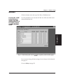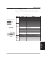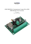
1
User Manual
AlphaMax 82A
AlphaMax 82S
Alarm and Control Network Element
Um108279
AlphaMax 82A and AlphaMax 82S
Version 2.2B
Alarm and Control Network Elements
Publication Number UM00A.26120
Date of issue: 10-26-00
4955 E. Yale Ave.
Fresno, CA 93727
Phone (559) 454-1600 / FAX (559) 454-1688 / Toll-free (800) 622-3314
e-mail - [email protected]
http://www.dpstele.com
Copyright 2000, DPS Telecom
i
Warranty
DPS Telecom products are warranted to be free from defects in material and workmanship at the time of sale.
DPS Telecom’s. obligation under this warranty is limited to the replacement of any hardware proved to be
defective within one year from the date of delivery and the replacement of any software for ninety days from the
date of delivery. If the product malfunctions during the warranty period, DPS Telecom will repair it at its option at
no charge to the purchaser other than the cost of shipping to and from DPS Telecom, which shall be the
responsibility of the purchaser. Before using, the purchaser shall determine the suitability of the product for the
intended use and user assumes all risk and liability whatsoever in connection therewith. This warranty is made in
lieu of and excludes all other warranties, expressed or implied. The implied warranties of merchantability and
fitness for a particular use are specifically excluded. Neither seller nor manufacturer shall be liable for any other
injury, loss or damage, whether direct or consequential, arising out of the use of or the inability to use this product.
Purchaser shall fill out the requested information on the Product Warranty Card and mail it to DPS Telecom
This card provides information that helps DPS Telecom make product improvements as well as develop new
products that better suit our customer’s needs.
Extended Warranty
For an additional fee seller may make available to purchaser an extended warranty, providing an additional
period of time for the applicability of the standard warranty provided with hardware and software. If the product
malfunctions during the warranty period, DPS Telecom will repair it at its option at no charge to the purchaser
other than the cost of shipping to and from DPS Telecom, which shall be the responsibility of the purchaser. An
extended warranty, when purchased, is made in lieu of and excludes all other warranties, expressed or implied,
other than the standard warranty. The implied warranties of merchantability and fitness for a particular use are
specifically excluded. Neither seller nor manufacturer shall be liable for any other injury, loss or damage, whether
direct or consequential, arising out of the use of or the inability to use this product.
In Case of Failure
If a product should fail while in service, contact DPS Telecom for technical support. Many problems are fixed
with a simple phone call. Have available the invoice to determine if the product is under warranty. If the problem
cannot be solved over the telephone and the product is in warranty, DPS Telecom will authorize the return of the
product for service and will provide shipping information. If the product is out of warranty, repair charges will be
quoted and repairs will be made after the charges are authorized by the customer. All non-warranty repairs receive
an additional 90-day warranty.
Copyright Notice
All software and manuals are copyrighted by DPS Telecom Said software and manuals may not be
reproduced, copied, transmitted or used to make a derivative work, by either mechanical, electronic or any other
means, in whole or in part, without prior written consent from DPS Telecom, except as required by United States
Copyright laws. All rights reserved.
Trademark Acknowledgments
IBM is a registered trade mark of International Business Machines, Inc.
Windows, Windows 95, Windows 98, and Windows NT are registered trade marks of Microsoft Corp.
Notice
The information contained in this document is subject to change without notice. DPS Telecom assumes no
responsibility for any errors that may appear in materials or programs.
ii
Table of Contents
Table of Contents
Chapter 1 - Overview - - - - - - - - - - - - - - - - - - - - - - - 1
AlphaMax 82A and 82S - - - - - - - - - - - - - - - - - - - - - 2
Chapter 2 - Hardware Setup - - - - - - - - - - - - - - - - - - - - 5
AlphaMax 82A (model 245) - - - - - - - - - - - - - - - - - - - 6
AlphaMax 82A (model 246) - - - - - - - - - - - - - - - - - - - 8
AlphaMax 82S (model 247) - - - - - - - - - - - - - - - - - - - 10
AlphaMax 82A with optional single connector block - - - - - - 12
AlphaMax 82A with optional UPS connector block - - - - - - - 14
AlphaMax 82A with panel mounted wire wrap block - - - - - - 16
Chapter 3 - Software Setup - - - - - - - - - - - - - - - - - - - - 19
T/AlphaW Software - - - - - - - - - - - - - - - - - - - - - - - 20
Tconfig - - - - - - - - - - - - - - - - - - - - - - - - - - - - - 20
Configuration Data (Fill In)- - - - - - - - - - - - - - - - - - - 21
Install T/AlphaW - - - - - - - - - - - - - - - - - - - - - - - - 22
Start T/AlphaW - - - - - - - - - - - - - - - - - - - - - - - - - 23
Define a New Device - - - - - - - - - - - - - - - - - - - - - - 24
Edit an Existing Device - - - - - - - - - - - - - - - - - - - - - 25
Pagers- - - - - - - - - - - - - - - - - - - - - - - - - - - - - - 26
Alarms - - - - - - - - - - - - - - - - - - - - - - - - - - - - - 27
Relays- - - - - - - - - - - - - - - - - - - - - - - - - - - - - - 28
Advanced - Site Definition - - - - - - - - - - - - - - - - - - - 29
Advanced - Pagers - - - - - - - - - - - - - - - - - - - - - - - 30
Advanced - Alarms - - - - - - - - - - - - - - - - - - - - - - - 31
Advanced - Relays - - - - - - - - - - - - - - - - - - - - - - - 32
Save your file - - - - - - - - - - - - - - - - - - - - - - - - - - 33
Select your computer’s modem. - - - - - - - - - - - - - - - - - 34
Write (Download) Configuration to AlphaMax - - - - - - - - - 35
Ring Bypass Feature - - - - - - - - - - - - - - - - - - - - - - 36
Software Menu Chart - - - - - - - - - - - - - - - - - - - - - - 38
iii
Table of Contents
Chapter 4 - Checkout - - - - - - - - - - - - - - - - - - - - - - - 39
Connect - - - - - - - - - - - - - - - - - - - - - - - - - - - - - 40
Test Alarms - - - - - - - - - - - - - - - - - - - - - - - - - - - 41
Test Controls - - - - - - - - - - - - - - - - - - - - - - - - - - 42
Test Pager - - - - - - - - - - - - - - - - - - - - - - - - - - - 43
Pager Test Feature - - - - - - - - - - - - - - - - - - - - - - - 44
Chapter 5 - Operation - - - - - - - - - - - - - - - - - - - - - - 45
AlphaNumeric Pager - - - - - - - - - - - - - - - - - - - - - - 46
Numeric Pager - - - - - - - - - - - - - - - - - - - - - - - - - 47
ASCII Terminal- - - - - - - - - - - - - - - - - - - - - - - - - 48
DTMF Direct Dial In - - - - - - - - - - - - - - - - - - - - - - 49
Advanced - Monitor Mode - - - - - - - - - - - - - - - - - - - 50
Advanced - LED Display Status- - - - - - - - - - - - - - - - - 51
Advanced - ASCII Through Port Access (82S) - - - - - - - - - 52
Advanced - Flow Chart - - - - - - - - - - - - - - - - - - - - - 53
Chapter 6 - Correcting a Malfunction- - - - - - - - - - - - - - - 55
How to Obtain Technical Support After Hours - - - - - - - - - 56
Checklist - - - - - - - - - - - - - - - - - - - - - - - - - - - - 57
Chapter 7 - Frequently Asked Questions - - - - - - - - - - - - - 61
Chapter 8 - Specifications- - - - - - - - - - - - - - - - - - - - - 65
Features - - - - - - - - - - - - - - - - - - - - - - - - - - - - 66
AlphaMax Description - - - - - - - - - - - - - - - - - - - - - 67
UPS Connector Block Description - - - - - - - - - - - - - - - 69
Technical Description - - - - - - - - - - - - - - - - - - - - - - 70
AlphaMax Functional Schematic - - - - - - - - - - - - - - - - 71
AlphaMax 82A Specifications - - - - - - - - - - - - - - - - - - 72
AlphaMax 82S Specifications - - - - - - - - - - - - - - - - - - 73
UPS Connector Block Specifications - - - - - - - - - - - - - - 74
AlphaMax Part Numbers - - - - - - - - - - - - - - - - - - - - 75
Accessory Part Numbers - - - - - - - - - - - - - - - - - - - - 76
Index - - - - - - - - - - - - - - - - - - - - - - - - - - - - - - - 77
iv
Chapter 1 - Overview
Chapter 1
Chapter 1 - Overview
The following pages give a brief description of what the
AlphaMax can do for you.
Chapter 1 - Overview
AlphaMax 82A and 82S - - - - - - - - - - - - - - - - - - - - - 2
Cautions
Observe electrostatic precautions when servicing this equipment.
Observe polarity when connecting power to this unit.
There are no user serviceable parts inside the enclosure.
For intra-building connections, all interfaces must be connected
through a shielded cable that is grounded at both ends.
1
Chapter 1 - Overview
AlphaMax 82A and 82S
DPS’ AlphaMax 82A or 82S, teamed with your local pager service, will
let you know when you have an important event occurring at some
isolated, unmanned location. The AlphaMax can be supplied with a
“UPS” Connector Block with Battery Backup to simplify installation
and provide continued operation during power outages.
The AlphaMax can detect any event that can be translated into an
electrical signal, such as that coming from a micro switch or photo cell.
Door openings and equipment failures are typical events that it can
report on your pager. In addition, you can contact the AlphaMax from
any tone dialing telephone and, by password identification, activate
remote control devices like door locks or security lights. AlphaMax
has broad applications in many areas, including:
Telecommunications - The AlphaMax is just right for cell sites, small
offices and remote huts for monitoring tower lights and other critical
equipment. In addition to its pager reporting, telecom locations may
forward selected alarm points to a central monitoring system.
AlphaMax reports with TRIP protocol or ASCII messages.
Transportation - AlphaMax is ideal for monitoring crossing gates and
other safety devices and reporting problems via pager or cellular
phone.
Refrigeration - AlphaMax monitors freezer doors, temperature,
compressor operation and power lines, warning you of problems
before they become losses.
Manufacturing - AlphaMax monitors processes and equipment status
on-line, paging your maintenance and supervisory personnel
throughout a facility, 24 hours a day.
Security - AlphaMax can pinpoint entry violations to a specific door or
window. Security personnel are notified of activity even when they are
on another part of the property.
Agriculture - An AlphaMax in a barn or other out-building can notify
you of an unauthorized entry, temperature extreme, fire, low water
pressure, pump operation, etc. With AlphaMax’s remote control
capability, you can operate door locks, security lights and pumps. With
wide-area paging service, you can know the condition of your ranch or
farm no matter where you are.
2
Configuration Software - Configuring AlphaMax from your PC is easy
with the new T/Alpha for Windows(tm) (T/AlphaW) software, that runs
under Windows 95, Windows 98 or Windows NT. The software also
monitors alarms and operates control relays.
ASCII Port Access - The AlphaMax 82S has all the features outlined
above, plus the ability to remotely access the craft port of a nearby
device. This allows you to download instructions and obtain status
information from a PABX, server, radio, etc.
Mounting Accessories - A single connector block, a combination UPS
and connector block and a wire wrap block are available to assist your
AlphaMax installation.
-48 VDC Power
T/Alpha
(Configuration)
Normal
Mode
(82A
or 82S)
T/MonXM Workstation
or T/MonDL Software
8 Opto Inputs
2 Relay Outputs
4 Pagers
-48 VDC Power
ASCII
Mode
(82S)
Terminal
To
CRAFT
Port
Fig. 1 - AlphaMax reports alarms to a variety of devices.
3
Chapter 1
Chapter 1 - Overview
Chapter 1 - Overview
Connector Block
(Can be equipped with
optional UPS).
Wire-Wrap Block
Fig 2 - Mounting Accessories Simplify Installation
4
Chapter 2 - Hardware Setup
Chapter 2 - Hardware Setup
Chapter 2
The following pages tell you how to install and connect your
AlphaMax.
There are 6 variations of hardware setup. Go to the pages designated
below for the type of installation you are doing:
Chapter 2 - Hardware Setup
AlphaMax 82A (model 245), single ended inputs,
directly connected at J1 - - - - - - - - - - - - - - - - - - - - - 6
AlphaMax 82A (model 246), bipolar inputs,
directly connected at J1 - - - - - - - - - - - - - - - - - - - - - 8
AlphaMax 82S (model 247), single-ended inputs,
directly connected at J1 - - - - - - - - - - - - - - - - - - - - - 10
AlphaMax 82A with optional single connector block - - - - - - 12
AlphaMax 82A with optional UPS connector block - - - - - - - 14
AlphaMax 82A with panel mounted wire wrap block - - - - - - 16
5
Chapter 2 - Hardware Setup
AlphaMax 82A (model 245), single ended inputs,
directly connected at J1
The installer
1. Unpack the AlphaMax and all accessories. Check contents against
provides alarm
the shipping list that is packed in the box.
contacts, power
source and wires to 2. Fill out and mail the postage prepaid registration card.
the alarm and
control points.
3. Use the enclosed mounting template and hardware to mount the
AlphaMax.
NOTE
The AlphaMax is shipped with all necessary cables for installation.
4. Connect a phone line to the RJ12 jack (J5) on the AlphaMax.
5. Connect alarm points and controls to J1 on the AlphaMax. A DB25
connector and hood are supplied in the AlphaMax cable kit. Refer to
Fig 3.
NOTE
To operate an alarm, there must be an electrical path from the Alarm
(no.)A (input) pin to the Alarm (no.)B (return) pin. Example: (see Fig. 3)
To operate alarm point 5, J1-pin 7 (Alarm 5A) connects to one terminal
of a (normally-open) switch or relay contact. J1-pin 19 (Alarm 5B)
connects to the other terminal of the switch or relay contact. When the
switch or relay contact closes, current flows in the circuit and an alarm is
sensed.
Do not connect
6a. If you are using AC Power - Connect the power adapter to J4 on
power adaptor to the the AlphaMax, then plug the adaptor into an AC outlet.
AlphaMax while
“hot.”
6b. If you are using DC Power - A DC supply may be connected to J1
pins 1 (- gnd) and 14 (+) on the AlphaMax.
7. Go to Chapter 3 - Software Setup on page 19.
6
Chapter 2 - Hardware Setup
AC Adaptor Ground
6 Not Connected
5 Not Connected
4 Ring
3 Tip
AC Adaptor +9VDC
3.5 mm Plug
+9 VDC (Inside)
Ground
Twist collar
to lock
J4
2 Not Connected
J5
1 Not Connected
Chapter 2
Screw-on Plug (Comes
with later models)
J1
AlphaMax 82A
Model 245 (single-ended opto inputs)
PIN # DESCRIPTION
1
2
3
4
5
6
7
8
9
10
11
12
13
Power Ground *
Not Connected (model 245)
Alarm 1A
Alarm 2A
Alarm 3A
Alarm 4A
Alarm 5A
Alarm 6A
Alarm 7A
Alarm 8A
Control 1-Normal Close
Control 1-Normal Open
Control 1-Common
PIN # DESCRIPTION
14
+ Power Input *
15
16
17
18
19
20
21
22
23
24
25
Alarm 1B
Alarm 2B
Alarm 3B
Alarm 4B
Alarm 5B
Alarm 6B
Alarm 7B
Alarm 8B
Control 2-Normal Close
Control 2-Normal Open
Control 2-Common
FEMALE DB25
13 12 11 10 9
8
7
6
5
4
3
2
1
25 24 23 22 21 20 19 18 17 16 15 14
Connect Alarm A points
to Alarm B points
through alarm contact.
A
B
Switch
or Relay Contact
* NOT REQUIRED WHEN AC WALL TRANSFORMER IS USED.
Fig. 3 - Connect alarm and control points at the DB25 connector on the AlphaMax 82A.
7
Chapter 2 - Hardware Setup
AlphaMax 82A (model 246), bipolar inputs, directly
connected at J1
The installer
1. Unpack the AlphaMax and all accessories. Check contents against
provides alarm
the shipping list that is packed in the box.
contacts, power
source and wires to 2. Fill out and mail the postage prepaid registration card.
the alarm and
control points.
3. Use the enclosed mounting template and hardware to mount the
AlphaMax.
NOTE
The AlphaMax is shipped with all necessary cables for installation.
4. Connect a phone line to the RJ12 jack (J5) on the AlphaMax.
5. Connect alarm points and controls to J1 on the AlphaMax. A DB25
connector and hood are supplied in the AlphaMax cable kit. Refer to
Fig 4.
NOTE
To operate an alarm, there must be an electrical path from the Alarm
(no.)A (input) pin to the Alarm (no.)B (return) pin. This model
AlphaMax can use switched ground or switched battery.
Example: (see Fig. 4) Switched ground: To operate alarm point 5, J1-pin
7 (Alarm 5A) connects to one terminal of a (normally-open) switch or
relay contact. The other terminal of the switch or relay contact is
connected to negative ground. J1-pin 19 (Alarm 5B) connects to positive
battery. When the switch or relay contact closes, current flows in the
circuit and an alarm is sensed.
Switched battery: To operate alarm point 5, J1-pin 7 (Alarm 5A) connects
to negative ground. J1-pin 19 (Alarm 5B) connects to one terminal of a
(normally-open) switch or relay contact. The other terminal of the switch
or relay contact is connected to positive battery. When the switch or relay
contact closes, current flows in the circuit and an alarm is sensed.
Do not connect
6a. If you are using AC Power - Connect the power adapter to J4 on
power adaptor to the the AlphaMax, then plug the adaptor into an AC outlet.
AlphaMax while
“hot.”
6b. If you are using DC Power - A DC supply may be connected to J1
pins 1 (- gnd) and 14 (+) on the AlphaMax.
7. Go to Chapter 3 - Software Setup on page 19.
8
Chapter 2 - Hardware Setup
AC Adaptor Ground
6 Not Connected
5 Not Connected
4 Ring
3 Tip
AC Adaptor +9VDC
3.5 mm Plug
+9 VDC (Inside)
Twist collar
to lock
Ground
J4
2 Not Connected
J5
1 Not Connected
Chapter 2
Screw-on Plug (Comes
with later models)
J1
AlphaMax 82A
Model 246 (bi-polar opto inputs)
PIN # DESCRIPTION
1
2
3
4
5
6
7
8
9
10
11
12
13
FEMALE DB25
13 12 11 10 9
8
7
6
5
4
3
2
1
PIN # DESCRIPTION
Power Ground *
Power Ground (model 246)
Alarm 1A (-)
Alarm 2A(-)
Alarm 3A (-)
Alarm 4A (-)
Alarm 5A (-)
Alarm 6A (-)
Alarm 7A (-)
Alarm 8A (-)
Control 1-Normal Close
Control 1-Normal Open
Control 1-Common
14
+ Power Input *
15
16
17
18
19
20
21
22
23
24
25
Alarm 1B (+)
Alarm 2B (+)
Alarm 3B (+)
Alarm 4B (+)
Alarm 5B (+)
Alarm 6B (+)
Alarm 7B (+)
Alarm 8B (+)
Control 2-Normal Close
Control 2-Normal Open
Control 2-Common
25 24 23 22 21 20 19 18 17 16 15 14
Connect Alarm A points
to ground (-).
Connect Alarm B points
to + DC.
Put alarm contact in
either leg.
* NOT REQUIRED WHEN AC WALL TRANSFORMER IS USED.
Switched Battery
Switched Ground
A
Switch
or Relay Contact
B
+DC
A
B
+DC
Switch
or Relay Contact
Fig. 4 - Connect alarm and control points at the DB25 connector on the AlphaMax 82A.
9
Chapter 2 - Hardware Setup
AlphaMax 82S (model 247), single-ended inputs,
directly connected at J1
The installer
1. Unpack the AlphaMax and all accessories. Check contents against
provides alarm
the shipping list that is packed in the box.
contacts, power
source and wires to 2. Fill out and mail the postage prepaid registration card.
the alarm and
control points.
3. Use the enclosed mounting template and hardware to mount the
AlphaMax.
NOTE
The AlphaMax is shipped with all necessary cables for installation.
4. Connect a phone line to the RJ12 jack (J5) on the AlphaMax.
5. Connect alarm points and controls to J1 on the AlphaMax.
Connect ASCII reach-through port to J1 on the AlphaMax. A DB25
connector and hood are supplied in the AlphaMax cable kit. Refer to
Fig. 5.
NOTE
To operate an alarm, there must be an electrical path from the Alarm
(no.)A (input) pin to the Alarm (no.)B (return) pin. Example: (see Fig. 5)
To operate alarm point 5, J1-pin 7 (Alarm 5A) connects to one terminal
of a (normally-open) switch or relay contact. J1-pin 19 (Alarm 5B)
connects to the other terminal of the switch or relay contact. When the
switch or relay contact closes, current flows in the circuit and an alarm is
sensed.
Do not connect
6a. If you are using AC Power - Connect the power adapter to J4 on
power adaptor to the the AlphaMax, then plug the adaptor into an AC outlet.
AlphaMax while
“hot.”
6b. If you are using DC Power - A DC supply may be connected to J1
pins 1 (- gnd) and 14 (+) on the AlphaMax.
7. Go to Chapter 3 - Software Setup on page 19.
10
Chapter 2 - Hardware Setup
AlphaMax 82A with optional single connector block
AC Adaptor Ground
AC Adaptor +9VDC
3.5 mm Plug
+9 VDC (Inside)
6 Not Connected
Twist collar
to lock
Ground
5 Not Connected
4 Ring
3 Tip
1 Not Connected
J5
J4
M DB25 to F DB9 cable for ASCII
reach through port to terminal equipment
M DB25 to F DB9 cable for ASCII
reach through port to PC
Plugs in female
(DTE) connector
on Alphamax DB25
to
to
to
to
to
Plugs in male (DTE)
connector on typical
terminal equipment
DB25 Male
DB9 female
DB25 Male
Pin 14
Pin 1
Pin 2
Pin 15
Pin 16
Plugs in female
(DTE) connector
on Alphamax DB25
Plugs in male (DTE)
connector on PC for
configuration
Pin 2
Pin 3
Pin 1+8
Pin 7
Pin 5
DB9 female
Pin 14
Pin 1
Pin 2
Pin 15
Pin 16
to
to
to
to
to
Pin 2
Pin 3
Pin 4
Pin 1
Pin 5
J1
AlphaMax 82S
FEMALE DB25
13 12 11 10 9
8
7
6
5
4
3
2
1
25 24 23 22 21 20 19 18 17 16 15 14
Connect Alarm A points
to Alarm B points
through alarm contact.
A
B
Switch
or Relay Contact
Model 247 (single-ended opto inputs)
PIN # DESCRIPTION
1
2
3
4
5
6
7
8
9
10
11
12
13
RS232 RXD**
RS232 DTR**
Alarm 1A
Alarm 2A
Alarm 3A
Alarm 4A
Alarm 5A
Alarm 6A
Alarm 7A
Alarm 8A
Control 1-Normal Close
Control 1-Normal Open
Control 1-Common
PIN # DESCRIPTION
14
15
16
17
RS232 TXD**
RS232 DCD**
RS232 GND**
Alarm 1, 2 & 3B*
18
19
20
21
22
23
24
25
Alarm 4B
Alarm 5B
Alarm 6B
Alarm 7B
Alarm 8B
Control 2-Normal Close
Control 2-Normal Open
Control 2-Common
*Points 1, 2, and 3 Share a common (Ground) return pin.
** See table above.
Fig. 5- On the AlphaMax 82S, the DB25 connector provides access for alarm points, control points
and the ASCII reach-through port.
11
Chapter 2
2 Not Connected
Screw-on Plug (Comes
with later models)
Chapter 2 - Hardware Setup
The installer
1. Unpack the AlphaMax and all accessories. Check shipping list.
provides alarm
contacts, power
2. Fill out and mail the postage prepaid registration card.
source and wires to
the alarm and
3. Use the mounting template and hardware to mount the AlphaMax.
control points.
4. Mount connector block assembly within 3 feet of the AlphaMax.
5. Attach DB25 cable between connector block J1 and AlphaMax J1.
6. Connect a phone line to the RJ12 jack (J5) on the AlphaMax.
7. Connect all alarm and control points at the connector block. (Fig. 6)
NOTE
An electrical path from the Alarm (no.)A pin to the Alarm (no.)B pin
causes an alarm.
AlphaMax model 245 uses a “dry contact” switch.
Example: (see Fig.6) To operate alarm point 5, Alarm 5A connects to one
terminal of a (normally-open) switch or relay contact. Alarm 5B connects
to the other terminal. When the switch or relay contact closes, current
flows in the circuit and an alarm is sensed.
AlphaMax model 246 uses switched ground or switched battery.
Example: (see Fig. 6) Switched ground: To operate alarm point 5, Alarm
5A connects to one terminal of a (normally-open) switch or relay contact.
The other terminal connects to negative ground. Alarm 5B connects to
positive battery. When the switch or relay contact closes, current flows in
the circuit and an alarm is sensed.
Switched battery: To operate alarm point 5, Alarm 5A connects to
negative ground. Alarm 5B connects to one terminal of a (normally-open)
switch or relay contact. The other terminal connects to positive battery.
When the switch or relay contact closes, current flows in the circuit and
an alarm is sensed.
Do not connect a
8a. If you are using AC Power - Connect the power adapter to J4 on
“hot” power adaptor the AlphaMax, then plug the adaptor into an AC outlet.
to the AlphaMax.
8b. If you are using DC Power - A DC supply may be connected to
Do not remove the
pins J2-1 (+) and J2-2 (negative ground) on the connector block.
DB25 cable while
power is applied.
9. Go to Chapter 3 - Software Setup on page 19.
12
CTRL 1 COM.
CTRL 1 N.O.
CTRL 1 N.C.
CTRL 2 COM.
CTRL 2 N.O.
CTRL 2 N.C.
ALARM 8A
ALARM 8B
ALARM 7A
ALARM 7B
ALARM 6A
ALARM 6B
ALARM 5A
ALARM 5B
ALARM 4A
ALARM 4B
ALARM 3A
ALARM 3B
ALARM 2A
ALARM 2B
ALARM 1A
ALARM 1B
POWER GND (-)
POWER INPUT (+)
Wire-Wrap pins
or Screw Lug
Terminals*
Chapter 2
Chapter 2 - Hardware Setup
AlphaMax
Connector
Block
J4
J1
J3
*Screw Lugs illustrated
Wire-Wrap pins follow
same pattern.
J2
Model D-PC-254-10A-00 has wire-wrap pins
Model D-PC-254-10A-10 has screw lug terminals
Installation
1. Remove connector block cover.
2. Mount block assembly.
3. Connect wires to alarm and control points.
4. Connect power.
5. Connect DB25 cable between block assembly
and AlphaMax.
Fig. 6 - Single Connector Block comes with Screw Lug Terminals (non-UPS).
13
Chapter 2 - Hardware Setup
AlphaMax 82A with optional UPS connector block
The installer
1. Unpack the AlphaMax and all accessories. Check shipping list.
provides alarm
contacts, power
2. Fill out and mail the postage prepaid registration card.
source and wires to
the alarm and
3. Use the mounting template and hardware to mount the AlphaMax.
control points.
4. Mount Connector Block Assembly within 3 feet of the AlphaMax.
Do not remove
5. Jumpers are factory set. If it is absolutely necessary to change
cables from the
jumpers or to change the fuse, remove cover as follows:
AlphaMax or the UPS
a. Remove three screws.
while power is
b. Remove nut from PWR 1 jack.
applied.
c. Remove bolts from DB25 connector.
d. Rock cover back.
Use only the
e. Change jumpers as needed. (See detail in Fig. 7.)
batteries
f. Reverse procedure to reinstall cover.
supplied
with the
unit. Other 6. Connect the 3 foot DB25 cable between J1 on the UPS Connector
batteries will not
Block and J1 on the AlphaMax.
provide the rated
performance and
7. Connect a phone line to the RJ12 jack (J5) on the AlphaMax.
may damage the
charging circuitry.
8. Connect all alarm and control points at the connector block. (Fig. 7)
WARNING!
DO NOT REMOVE CABLES
FROM THE ALPHAMAX
OR THE UPS WHILE
POWER IS APPLIED!
WARNING!
NOTE
14
An electrical path from the Alarm (no.)A pin to the Alarm (no.)B pin
causes an alarm.
AlphaMax model 245 uses a “dry contact” switch.
Example: (see Fig. 7) To operate alarm point 5, Alarm 5A connects to
one terminal of a (normally-open) switch or relay contact. Alarm 5B
connects to the other terminal. When the switch or relay contact closes,
current flows in the circuit and an alarm is sensed.
AlphaMax model 246 uses switched ground or switched battery.
Example: (see Fig. 7) Switched ground: To operate alarm point 5, Alarm
5A connects to one terminal of a (normally-open) switch or relay contact.
The other terminal connects to negative ground. Alarm 5B connects to
positive battery. When the switch or relay contact closes, current flows in
the circuit and an alarm is sensed.
Switched battery: To operate alarm point 5, Alarm 5A connects to
negative ground. Alarm 5B connects to one terminal of a (normally-open)
switch or relay contact. The other terminal connects to positive battery.
When the switch or relay contact closes, current flows in the circuit and
an alarm is sensed.
Chapter 2 - Hardware Setup
Do not connect
9a. If you are using AC Power - Connect the power adapter to the
power adaptor to the PWR 1 jack on the UPS connector block assembly.
AlphaMax while
“hot.”
9b. If you are using DC Power - A DC supply may be connected to
Do not remove the
pins J2-1 (+) and J2-2 (negative ground) on the connector block.
DB25 cable while
power is applied.
3.5 mm Plug
CTRL 1 COM.
CTRL 1 N.O.
CTRL 1 N.C.
CTRL 2 COM.
CTRL 2 N.O.
CTRL 2 N.C.
Screw Lug
Terminals
J4
ALARM 8A
ALARM 8B
ALARM 7A
ALARM 7B
ALARM 6A
ALARM 6B
ALARM 5A
ALARM 5B
ALARM 4A
ALARM 4B
ALARM 3A
ALARM 3B
ALARM 2A
ALARM 2B
ALARM 1A
ALARM 1B
Screw-on Plug (Comes
with later models)
UPS
Connector
Block
J5
J1
J3
Batteries
Located
Under P.C.
Board
J7
3 Foot Cable
LED
J6
J1
PWR 1
J2
NOTE: Use
the UPS only
with AlphaMax 82A
(models 245 & 246)
Fuse
(250 ma)
Remove cover for access to jumpers
9-12 Volt Supply (default)
J6
J7
12-27 Volt Supply
Power
Failure
Alm. to Pt. 2
J5
*NOT REQUIRED WHEN AC WALL
TRANSFORMER IS USED.
J8
J8
Model 246, bipolar inputs
Model 245, single-ended inputs
Connect Alarm A points
to Alarm B points
through alarm contact.
B
2 Batteries Installed
1 Battery Installed (default)
Power
Failure
Alm. to Pt. 8
J5
Connect Alarm A points to ground (-).
Connect Alarm B points to + DC.
Put alarm contact in either leg.
J5
J8
No Power
alarm
(default)
Switched Battery
Switched Ground
Switch
or Relay Contact
J5
J8
*POWER GND (-)
*POWER INPUT (+)
A
J4
Chapter 2
10. Go to Chapter 3 - Software Setup on page 19.
+DC
A
B
+DC
A
B
Switch
or Relay Contact
Switch
or Relay Contact
Fig. 7 - UPS single Connector Block Provides up to 3 Hours of Battery Backup.
15
Chapter 2 - Hardware Setup
AlphaMax 82A with panel mounted wire wrap block
The installer
1. Unpack the AlphaMax and all accessories. Check contents against
provides alarm
the shipping list that is packed in the box.
contacts, power
source and wires to 2. Fill out and mail the postage prepaid registration card.
the alarm and
control points.
3. Use the enclosed mounting template and hardware to mount the
AlphaMax.
NOTE
If you are using a DPS rack mount panel, up to two AlphaMaxes and the
wire wrap block can be mounted on a panel.
4. Remove the wire wrap block cover.
5. Mount block assembly to panel or other flat surface.
6. Plug cable into AlphaMax.
7. Connect a phone line to the RJ12 jack (J5) on the AlphaMax.
8. Connect all alarm and control points at the wire wrap block. (Fig. 8)
NOTE
16
An electrical path from the Alarm (no.)A pin to the Alarm (no.)B pin
causes an alarm.
AlphaMax model 245 uses a “dry contact” switch.
Example: (see Fig. 8) To operate alarm point 5, wire wrap block pin A-7
(Alarm 5A) connects to one terminal of a (normally-open) switch or relay
contact. Wire wrap block pin B-9 (Alarm 5B) connects to the other
terminal. When the switch or relay contact closes, current flows in the
circuit and an alarm is sensed.
AlphaMax model 246 uses switched ground or switched battery.
Example: (see Fig. 8) Switched ground: To operate alarm point 5, wire
wrap block pin A-7 (Alarm 5A) connects to one terminal of a
(normally-open) switch or relay contact. The other terminal connects to
negative ground. Wire wrap block pin B-9 (Alarm 5B) connects to
positive battery. When the switch or relay contact closes, current flows in
the circuit and an alarm is sensed.
Switched battery: To operate alarm point 5, wire wrap block pin A-7
(Alarm 5A) connects to negative ground. Wire wrap block pin B-9 (Alarm
5B) connects to one terminal of a (normally-open) switch or relay
contact. The other terminal connects to positive battery. When the switch
or relay contact closes, current flows in the circuit and an alarm is sensed.
Chapter 2 - Hardware Setup
Do not connect
9a. If you are using AC Power - Connect the power adapter to J4 on
power adaptor to the the AlphaMax, then plug the adaptor into an AC outlet.
AlphaMax while
“hot.”
9b. If you are using DC Power - DC power may be taken through the
Do not remove the
wire wrap block at pins F-1 (+) and F-3 (negative ground). (This
DB25 cable while
arrangement is only suitable for +24 V operation. It utilizes the fusing
power is applied.
provided on the wire wrap block.)
Chapter 2
10. Go to Chapter 3 - Software Setup on page 19.
F1
F2
Wire Wrap Block Pin-Out
WWB1
AlphaMax
Number 1
WWB2
AlphaMax
Number 2
J1
J2
D-PC-260-10A-00
Wire Wrap Pins, typical WWB1 and WWB2
Mount on a
D-PC-140-10A-00
or
D-PC-150-10A-00
panel for rack
installation.
Alarm Input & A
Control Output
Wires
Fuse
F
1
10
Installation
1. Remove wire wrap block cover.
2. Mount block assembly.
3. Connect wires to alarm and control points.
4. Plug cable into AlphaMax.
5. Remove fuse.
6. Connect power.
7. Replace fuse.
W/W Blk
Pin No.
A-1
A-2
A-3
A-4
A-5
A-6
A-7
A-8
A-9
A-10
B-1
B-2
B-3
B-4 (fuse)
B-5
B-6
B-7
B-8
B-9
B-10
C-1
C-2
C-3
C-4
C-5
F-1
F-2
DB25
Pin No.
1
2
3
4
5
6
7
8
9
10
11
12
13
14
15
16
17
18
19
20
21
22
23
24
25
Function
Power Ground (-)
No Connection
Alarm 1A
Alarm 2A
Alarm 3A
Alarm 4A
Alarm 5A
Alarm 6A
Alarm 7A
Alarm 8A
Control 1 N.C.
Control 1 N.O.
Control 1 Com.
+ Power Input
Alarm 1B
Alarm 2B
Alarm 3B
Alarm 4B
Alarm 5B
Alarm 6B
Alarm 7B
Alarm 8B
Control 2 N.C.
Control 2 N.O.
Control 2 Com.
Fuse Input (w/w block only)
Ground Input (w/w block only)
Fig. 8 - Wire Wrap Block Supports One or Two AlphaMax 82As.
17
Chapter 2 - Hardware Setup
NOTES
18
Chapter 3 - Software Setup
Chapter 3 - Software Setup
The following pages tell you how to prepare a configuration
file and write (download) it to your AlphaMax.
Chapter 3 - Software Setup
T/AlphaW Software - - - - - - - - - - - - - - - - - - - - - - - 20
Tconfig - - - - - - - - - - - - - - - - - - - - - - - - - - - - - 20
Configuration Data (Fill In)- - - - - - - - - - - - - - - - - - - 21
Install T/AlphaW - - - - - - - - - - - - - - - - - - - - - - - - 22
Start T/AlphaW - - - - - - - - - - - - - - - - - - - - - - - - - 23
Define a New Device - - - - - - - - - - - - - - - - - - - - - - 24
Pagers- - - - - - - - - - - - - - - - - - - - - - - - - - - - - - 26
Alarms - - - - - - - - - - - - - - - - - - - - - - - - - - - - - 27
Relays- - - - - - - - - - - - - - - - - - - - - - - - - - - - - - 28
Advanced - Site Definition - - - - - - - - - - - - - - - - - - - 29
Advanced - Pagers - - - - - - - - - - - - - - - - - - - - - - - 30
Advanced - Alarms - - - - - - - - - - - - - - - - - - - - - - - 31
Advanced - Relays - - - - - - - - - - - - - - - - - - - - - - - 32
Save your file - - - - - - - - - - - - - - - - - - - - - - - - - - 33
Select your computer’s modem. - - - - - - - - - - - - - - - - - 34
Write (Download) Configuration to AlphaMax - - - - - - - - - 35
Ring Bypass Feature - - - - - - - - - - - - - - - - - - - - - - 36
Software Menu Chart - - - - - - - - - - - - - - - - - - - - - - 38
NOTE
The AlphaMax 82 A must be configured over a phone line through a
central office because the AlphaMax modem must receive a ring signal to
be activated. Two phone lines are required if the configuration is done
on-site: one for the AlphaMax and one for a DOS-based PC running
T/Alpha.
NOTE
The AlphaMax 82S may be configured over a phone line, as described
above, or it can also be configured directly through the craft port.
19
Chapter 3
Edit an Existing Device - - - - - - - - - - - - - - - - - - - - - 25
Chapter 3 - Software Setup
T/AlphaW Software
T/AlphaW software is used to configure the AlphaMax. T/AlphaW
may also be used to monitor alarm and control point status and to
operate control relays.
T/AlphaW software runs under Windows 95, 98 or NT.
NOTE
Tconfig
Your T/AlphaW program and files will normally be located in a
directory named Program Files\Tconfig\AlphaMax. (You can specify a
different directory when you install T/AlphaW.) All other DPS
configuration programs and files will also be located in the Tconfig (or
your specified) directory.
Table A - Configuration Procedure
Step
Action
Page
1
Install T/AlphaW
22
2
Start T/AlphaW
23
3
Define a new
device
Site
24
Pagers
26
Alarms
27
Relays
28
4
Save your file
33
5
Select your Computer’s modem
34
6
Download Configuration
35
7
Check Out
39
WARNING!
DO NOT REMOVE CABLES
FROM THE ALPHAMAX
OR THE UPS WHILE
POWER IS APPLIED!
WARNING!
20
Always use the “Exit” function from the Edit Menu to quit the program.
NEVER turn off the computer before exiting. Doing so can corrupt data
files!
Chapter 3 - Software Setup
Configuration Data (Fill In)
Record information in the Table B before starting configuration:
Table B - Configuration Data
Site Definition
Site Name
Comment
Site Number
Phone Number
Advanced
Use only to change parameters for the AlphaMax modem. See Fig. 19.
Pagers
User Number
Device Type
Dial String
Alpha Pager PIN
Password
1
2
4
Advanced
Use only to change paging parameters like call out delay, redial attempts, TAP baud, word length, parity and stop bits.
See Fig. 20.
Alarms
Alarm Number
Description
Primary Pager User
Number
Time to wait to
Acknowledge
Secondary Pager
User Number
Number of
times to
report
1
2
3
4
5
6
7
8
Advanced
Use only to change the default settings for alarm qualification period, whether to call when an alarm clears, to change
the polarity (alarm on closed contact to alarm on open contact) and the qualification period base time. See Fig. 21.
Relays
Relay Number
Description
1
2
Advanced
Use only to define a derived control point. (Control point activated by an alarm or combination of alarm conditions.)
See Fig. 22.
21
Chapter 3
3
Chapter 3 - Software Setup
Install T/AlphaW
1. Place the T/AlphaW disk in the A: drive.
2, Click the Start
button.
3. Click Run.
Type a:\amax in the
Run box
Fig. 9 - Install T/AlphaW software from your
Windows desktop.
4. Type A:\AMAX in the run box that appears.
5. A window titled “Win Zip Self-Extractor [AMAX.EXE]” will
appear. Click on the setup button in this window.
6. The Installshield wizard will run. Follow the instructions on the
screen.
7. When installation is completed, you may wish to create an
AlphaMax icon on your desktop. Follow standard Windows procedure
to do this.
8. Go to page 23.
22
Chapter 3 - Software Setup
Start T/AlphaW
You can launch the program file at the end of the installation or later
by double clicking the Shortcut to
AlphaMax icon on your desktop. If
you have not created an icon, launch
the program using one of the many
ways provided by your windows
desktop (use Windows Explorer or My
Computer or click Start, Programs,
AlphaMax, etc.)
Fig. 10 - Double click the
AlphaMax icon to launch
T/AlphaW.
Chapter 3
If you have existing Enter your initials in the initials box.
data files created
under DOS versions
of T/Alpha, use
“Tools - Import
Device” to convert to
Windows format.
Fig. 11 - Your initials are recorded
for future reference.
The T/AlphaW screen will
appear. The New
Device definition box
will be displayed.
Go on to page 24.
Fig. 12 - Unique site information is entered in
the Site Definition box.
23
Chapter 3 - Software Setup
Define a New Device
Site - Use the information you entered in Table A to fill in the fields in
the Site Definition box.
Fig. 13 - Record details about the site in the Site Definition box.
T/AlphaW can
If you need to change parameters for the AlphaMax modem, click
maintain several
Advanced. See page 29.
configurations. New
configurations can Go on to Pagers on page 26.
be added and
existing ones can be
edited or deleted.
NOTE
24
For an explanation of any item, click on the field and press F1. The
context-sensitive help screen will appear.
Chapter 3 - Software Setup
Edit an Existing Device
If you wish to edit an existing device, click File on the T/AlphaW
menu bar.
Select Open
Device from the
drop down menu.
Select the desired
file from the
directory listing
that appears.
The Site
Fig. 14 - You can open an existing configuration in
Definition box
the Open Device window.
will appear. Edit
information in
the Site Definition box as necessary.
Fig. 15 - An existing configuration can be renamed to make a new one.
Click on the tab(s) for other parameter(s) you wish to edit, and change
as needed. Go to pages 33-35 for save and download instructions.
25
Chapter 3
T/AlphaW can
maintain several
configurations. New
configurations can
be added and
existing ones can be
edited or deleted.
Chapter 3 - Software Setup
Pagers
Click the Pager tab at the top of the Device Definition box.
Be sure to include a Use the information you entered in Table A to fill in the fields in the
“1” if dialing long
Pager Definition box.
distance or “9” if
dialing through a
PABX*.
Fig. 16 - Define up to four “pager” devices for the AlphaMax to call.
Phone numbers for numeric pagers should be followed by 2 commas
to provide delay.
To reduce the
possibility of
unauthorized
access, change all
User ID Numbers
from the default.
NOTE
If you need to change paging parameters, click Advanced. See page
30.
Go on to Alarms on page 27.
For proper Alpha pager operation you need your TAP* terminal phone
number and your PIN.
*See Chapter 7 for definitions.
26
Chapter 3 - Software Setup
Alarms
Click the Alarms tab at the top of the Device Definition box.
Use the information you entered in Table A to fill in the fields in the
Alarms Definition box.
Chapter 3
If using the “UPS”
battery-backup
option, you may
define point 2 or 8
for battery alarm,
CLOSED NORMAL
state.
Fig. 17 - Each alarm point can be assigned to a primary and secondary pager
device.
If you need to change default settings for the Alarms, click Advanced.
See page 31.
Go on to Relays on page 28.
27
Chapter 3 - Software Setup
Relays
Click the Relays tab at the top of the Device Definition box.
Use the information you entered in Table A to fill in the fields in the
Relay Definition box.
Fig. 18 - Assign a description for each control point.
If you need to define derived controls, click Advanced. See page 32.
Go on to Save your file on page 33.
28
Chapter 3 - Software Setup
Advanced - Site Definition
Chapter 3
The Site Definition - Advanced box is used to change the AlphaMax’s
modem parameters.
Fig. 19 - Set modem parameters in the Site Definition - Advanced window.
NOTE
NOTE
For an explanation of any item, click on the field and press F1. The
context-sensitive help screen will appear.
If you are using the Ring Bypass Features, see pages 36 and 37.
After you have completed Advanced - Site Definitions, go to page 26.
29
Chapter 3 - Software Setup
Advanced - Pagers
The Pagers - Advanced box is used to set paging parameters, define
alarm reporting messages and define the characters used for periodic
status reporting.
Fig. 20 - Set pager details in the Pagers - Advanced window.
NOTE
Alarm and Clear Messages are used in COS reports to Alpha pagers.
These reports show only the point that has changed.
NOTE
Alarm and Clear Characters are used in periodic status reports to Alpha
pagers. These reports list all points.
After you have completed Advanced - Pagers, go to page 27.
30
Chapter 3 - Software Setup
Advanced - Alarms
Chapter 3
The Alarms - Advanced box is used to set timing, polarity, repetition
parameters and call when clear option. It is also used to define special
applications for alarm point 1 and control relay 1.
Fig. 21 - Set alarm details in the Alarms - Advanced window.
NOTE
For an explanation of any item, click on the field and press F1. The
context-sensitive help screen will appear.
After you have completed Advanced - Alarms, go to page 28.
31
Chapter 3 - Software Setup
Advanced - Relays
The Relay 1 - Advanced and Relay 2- Advanced boxes are used to
define derived controls.
Derived Controls:
These are AND
terms, i.e. when
1,3,&5 are
marked, then all 3
must have alarms
for the relay to
actuate
A derived control is
a relay actuation
which occurs after a
logical group of
alarms are set or
cleared. You
control the logical
AND, OR, TRUE,
and FALSE
functions through
your inputs in this
table.
Fig. 22 - Program derived controls in the Relay 1 - Advanced
or Relay 2 - Advanced window.
NOTE
For an explanation of any item, click on the field and press F1. The
context-sensitive help screen will appear.
This derived control screen is composed of two matrices that are
logically “OR’d” Each matrix consists of 3 rows (alarm status) by 8
columns (alarm points). The alarm points in each set are logically
“AND’d”, which means that “ALL” of the columns must evalute
“TRUE” in order for the matrix to be true.
Example 1: If you declare an alarm when points 1, 3, & 5 are set, then
simply set those points under the “When these alarms are set” row.
Be sure to mark all the other alarms as “These alarms don’t matter.”
The “These alarms are clear” row would only be used if you wish to
declare an alarm when those marked points are “not” in alarm.
32
Chapter 3 - Software Setup
Example 2: If you wish to declare an alarm when point 3 or point 5
fails, then you would do the following:
Mark point 3 in the “when these alarms are set” position of the FIRST
matrix (Activate Relay). Make sure all other points in that matrix are
set to the “These alarms don’t matter” row.
Mark point 5 in the “when these alarms are set” position of the
SECOND matrix (OR Activate Relay). Make sure all other points in
that matrix are set to the “These alarms don’t matter” row.
After you have completed Advanced - Relays, go to Save your file.
Save your file
Chapter 3
When you have finished entering the configuration data, click File,
Save Device As. Type a name in the Save As box and click OK.
Go on to Select your computer’s modem on page 34.
Fig. 23 - Select a directory and enter a name for your file before saving.
33
Chapter 3 - Software Setup
Select your computer’s modem.
Before you can download a configuration file to the AlphaMax, you
must select your computer’s modem or serial port (AlphaMax 82S
only).
AlphaMax 82A
connects via dial
modem. AlphaMax
82S can connect via
dial modem or serial
port at J1 (Fig. 5).
To reduce the
possibility of
unauthorized
access, change all
User ID Numbers
from the default.
34
Click Connect. The
Connect options box
will appear. Click the
down arrow in the
Line Names field.
Select the modem or
serial port you are
using. (The list will
show only those
modems or ports that
are equipped on your
computer. Most
likely you have only
one modem. If so, it
will already be
selected.) Do not
change any modem
or port settings
unless you later have
problems connecting
to your AlphaMax.
Fig. 24 - Your computer’s modem will be listed
in the Line Name field.
The first time you write a configuration file to a new AlphaMax, you
must enter the default “1” in the password box. Any time you write to
an AlphaMax with a password change for user number 1, the old
password must be entered in the password box.
Go on to Write (Download) Configuration to AlphaMax on page 35.
Chapter 3 - Software Setup
Write (Download) Configuration to AlphaMax
Click the Connect button. It will take several seconds to establish the
connection.
NOTE
If your modem does not connect to the AlphaMax, you may need to
adjust the Baud. Click on the Line Properties button in the Connect
Options box. If your modem is an older version that operates at 14.4 K
Baud or less, change to 1200 Baud. If your modem is a newer one that
operates at 19.2K Baud or greater, change to 19200 Baud.
If you still have problems, contact DPS tech support at
1-800-622-3314.
Click the “Write to AlphaMax” button to start writing the file. A box
will show the progress.
NOTE
Chapter 3
Upon completion the Cancel button will say “Done.” Click on this
button to begin the exit procedure.
If you click the Cancel button before the writing procedure is done, your
AlphaMax may have an incomplete configuration file. You will need to
perform a complete “write to” before it will work properly.
Click the disconnect button.
Exit T/AlphaW or proceed with other activities. (We recommend that
you perform the checkout procedure beginning on page 40.)
35
Chapter 3 - Software Setup
Ring Bypass Feature
The AlphaMax 82A and 82S, ver. 2.1D offers an “answering machine
bypass” feature not available on previous versions. This new feature
allows the AlphaMax to share the phone line with an answering
machine, modem, FAX or any other device that answers after a set
number of rings. In this application, you let the phone ring a set
number of times (2, for example) when calling the AlphaMax, then
hang up. When you call back within another set time period (60
seconds, for example) the AlphaMax will answer on a specified ring (1,
for example). The answering machine must be set to answer on a later
ring (4, for example).
The Ring Bypass function is defined in the Site Definition - Advanced
screen. Refer to the illustration below and Table C.
Fig. 25 - Ring Bypass parameters are defined
in the Site Definition - Advanced window.
Return to page 29.
36
Chapter 3 - Software Setup
Table C - Ring Bypass Function is defined in the Site Definition / Advanced Screen
Field Name
Description
Ring Bypass
(Check box to enable)
Allows you to set conditions for the answering machine bypass feature. The following diagram shows an example of the time sequence for the bypass:
Answering Machine On
(Answering Machine set to answer in 5 rings)
Ring
1
2
Bypass Rings = 1
Ring
Hang up
Bypass Break
= 10 sec.
Dial again
1
AlphaMax
answers
Bypass Active = 30 sec.
Break sets the number of seconds between sets of rings before the bypass window opens (the minimum time
you must wait before redialing). (5 to 15 sec. Set 0 to disable) This must be greater than the time between
rings, which is typically 5 seconds.
Active sets the time the bypass window is to remain open (the maximum time you have to redial).
(20 to 90 sec).
Rings sets the number of rings before the AlphaMax answers the second call (1 to 7 rings). NOTE: This must
be less than the number of rings before the answering machine answers.
NOTE: If there is no break between sets of rings and if the answering machine is off, the AlphaMax will answer on the Number of Rings setting (6 in the example above).
Squelch Time (Seconds)
AlphaMax 82S only. Delay after the dial-up craft port becomes active (1 to 90 sec.)
37
Chapter 3
Dial
Ring
Chapter 3 - Software Setup
Software Menu Chart
Connect Options
Connect
New Device
Open Device Shows list
Save Device
Save Device As Shows list
Delete Device
Print
Exit
Import Device
Reindex
Alarm Number (1 - 8)
Description
Primary Pager User Number
Wait to Ack (Min.)
Secondary pager user Number
Times to Repeat
Site Name
Comment
Site Number
Phone Number
User (1-4)
Device Type
Dial String
Alpha Pager Pin
Password
Modem Type
Baud
Word/Parity/
Stop Bits
Number of Rings
Modem Initialization
String
Squelch Time
Ring Bypass Enabled
Ring Bypass Break
Ring Bypass Active
Ring Bypass Rings
Contents
Index
File Properties
About
1 Description
2 Description
Momentary Activation
Period
Derived Controls
Qual Period mm:ss
Call when Clear
Normally Closed
Repetition Count
Repetition Time hh:mm
Qual Period Base Time
Use Alarm 1 for Local Ack
Activate Relay 1 on Change of State
Callout Delay
Redial Attempts
TAP Baud
TAP Word/Parity/Stop Bits
Alarm Message
Clear Message
Auto Ack ASCII Pager
Alarm Character
Clear Character
Report Interval
Report Power On
Report Periodic Status
For details about any item, click on the item and press F1.
38
Chapter 4 - Checkout
Chapter 4 - Checkout
After hardware and software have both been set up, use the
procedure on the following pages to verify that your
AlphaMax is doing its job correctly.
Chapter 4 - Checkout
Connect - - - - - - - - - - - - - - - - - - - - - - - - - - - - - 40
Test Alarms - - - - - - - - - - - - - - - - - - - - - - - - - - - 41
Test Controls - - - - - - - - - - - - - - - - - - - - - - - - - - 42
Test Pager - - - - - - - - - - - - - - - - - - - - - - - - - - - 43
Chapter 4
Pager Test Feature - - - - - - - - - - - - - - - - - - - - - - - 44
39
Chapter 4 - Checkout
Connect
After completing installation and configuration, the following routine
is recommended to verify proper operation.
NOTE
The AlphaMax 82A must be tested over a phone line because the modem
must receive a ring signal to be activated. Two phone lines are required if
the testing is done on-site: one for the AlphaMax and one for your PC.
The AlphaMax 82S can be tested the same way or it can be tested locally
with your computer’s serial port connected to the RS232 port (See Fig. 5).
NOTE
Some of these tests require a person at the AlphaMax location.
Proceed as follows:
1. Connect the configuration computer to the phone line (or serial
port if you are testing an AlphaMax 82S locally).
2. Double-click the AlphaMax icon on your desktop.
3. Select the proper file for the AlphaMax.
4. Click on the Connect menu at the top of the screen.
5. Click on “connect.” The modem will dial the AlphaMax. An activity
window will indicate progress. After the AlphaMax answers, the screen
will show all function buttons solid.
6. Click on the “Monitor” button. The monitor screen shows the status
of the 8 alarms. Points that are not alarmed will be listed as “Clear” on a
green background. Points that are alarmed will be listed as “Alarm” on a
red background. Points that are in alarm and waiting for a qualification
time to pass will be listed as “Qualifying” on a yellow background. The
point descriptions will also be listed. See Fig. 26.
NOTE
40
If you have any problems connecting, refer to Chapter 6.
Chapter 4 - Checkout
Test Alarms
Fig. 26 - The Monitor AlphaMax Alarms window shows alarmed points
in red and cleared points in green.
2. Acknowledge each alarm by clicking the Ack button beside the
point. All alarms can be acknowledged by clicking the Ack All button.
When an alarmed point is acknowledged, Ack goes away and the
background remains red.
3. Restore each point to normal. The display will show “Clear” on green
next to the point number.
4. Acknowledge each normal by clicking the Ack button next to the
alarm or acknowledge all by clicking the Ack All button. Ack goes
away and “Clear” remains green.
41
Chapter 4
1. Activate each point at the AlphaMax. (Alarms can be simulated by
placing jumpers at the appropriate pins on J1. See Chapter 2.) As each
point is activated the monitor display will show “Alarm” on red next to
the point number. If an alarm qualifying period has been specified for the
point, “Qualifying” will show yellow. When the qualification period has
passed, “Alarm” will show on red.
Chapter 4 - Checkout
Test Controls
WARNING!
DO NOT REMOVE CABLES
FROM THE ALPHAMAX
OR THE UPS WHILE
POWER IS APPLIED!
WARNING!
Control points will be operated in this test. If any undesirable results will
occur from operating a control point, it should be disconnected from the
equipment and tested with a continuity indicator.
For
1. Click on the relays tab to highlight the Control Status window of
definitions of control the monitor screen. Relays that are not operated will be listed as
terminology, see
“Released” on a green background and relays that are operated will be
Chapter 7
listed as “Active” on a red background. The relay descriptions will also be
listed.
Fig. 27 - The Monitor AlphaMax Relays window shows active points
in red and released points in green.
2. Click on Relay 1 “Latch.” The status box will show “Active” on a red
background.
3. Click on Relay 1 “Latch.” The status box will show “Released” on a
green background.
4. Click on Relay 1 “Mom.” The status box will briefly show “Active” on
a red background. It will automatically change to “Released” on a green
background when the momentary control period has passed.
5. Repeat the above steps for Relay 2.
6. Click on the Exit Monitor button.
7. Click on the Disconnect button.
8. Close T/AlphaW.
9. Disconnect computer from phone line.
42
Chapter 4 - Checkout
Test Pager
1. Activate one alarm point. “Alarms” LED on the AlphaMax should
blink.
On ASCII devices be sure to check alarm display at the ASCII terminal,
as well as at pagers, if used.
NOTE
2. Observe alarm report on pager (or ASCII terminal). (This may take
several minutes depending on how busy the pager service is.)
Refer to Chapter 5 for pager display information.
NOTE
3. Call the AlphaMax on a tone dial phone. When the AlphaMax has
answered with two beeps, enter your device number (1 - 4) and
password, then press #. You should hear two more beeps. Press the
alarm point number plus # to acknowledge the alarm. (Refer to
Chapter 5 for further operating instructions.) “Alarms” LED on
AlphaMax should be on solid.
WARNING!
Control points will be operated in the rest of this test. If any undesirable
results will occur from operating a control point, it should be disconnected
from the equipment and tested with a continuity indicator.
Chapter 4
WARNING!
DO NOT REMOVE CABLES
FROM THE ALPHAMAX
OR THE UPS WHILE
POWER IS APPLIED!
4. Press 81# to latch control point 1.
5. Confirm control point 1 operation by having someone observe the
controlled equipment for the proper reaction.
6. Press 80# to release the control point.
7. Confirm control point release.
8. Hang up the phone.
9. Test additional alarm and control points as desired. Be sure to wait
for each alarm to be paged before attempting to call the AlphaMax to
acknowledge.
10. Test complete. Restore all alarm and control point connections to
normal.
43
Chapter 4 - Checkout
Pager Test Feature
Fig. 28 shows a Pager test window that can be accessed while your
computer is connected to the AlphaMax in the Monitor function. This
function allows you to verify the phone numbers used for the last page
and to issue a test message.
If you click in the Test box for a user number, a status page will be
issued to that pager after you disconnect from the AlphaMax.
If your pager is working correctly, you should receive a status report
on your pager within a short period of time. The actual time will
depend on how soon your pager service can respond.
Fig. 28 - The pager Test window allows you to issue a test message to your pager.
44
Chapter 5 - Operation
Chapter 5 - Operation
Once your AlphaMax is on line, use the instructions on the
following pages to learn how to read reports and send
commands.
Chapter 5 - Operation
AlphaNumeric Pager - - - - - - - - - - - - - - - - - - - - - - 46
Numeric Pager - - - - - - - - - - - - - - - - - - - - - - - - - 47
ASCII Terminal- - - - - - - - - - - - - - - - - - - - - - - - - 48
DTMF Direct Dial In - - - - - - - - - - - - - - - - - - - - - - 49
Advanced - Monitor Mode - - - - - - - - - - - - - - - - - - - 50
Advanced - LED Display Status- - - - - - - - - - - - - - - - - 51
Advanced - ASCII Through Port Access (82S) - - - - - - - - - 52
Chapter 5
Advanced - Flow Chart - - - - - - - - - - - - - - - - - - - - - 53
45
Chapter 5 - Operation
AlphaNumeric Pager
AlphaNumeric pagers show both Change of State (COS) and Status
reports. Refer to Fig. 29. The COS report uses the alarm / clear
messages defined in the Pager / Advanced screen (Fig. 20). The Status
report uses the alarm and clear characters defined in the same screen.
The appearance of the report may vary depending on the pager and
pager company, but the order in which the information is presented
will remain the same.
PAGER
REPORT
NUMBER
Alphanumeric Pager
C.O.S. Report
STATUS
MESSAGE
(uses alarm or
clear message)
ALARM POINT
STATUS, 1 - 8
(Uses Alarm and Clear
Characters - Points 4
and 6 are alarmed)
POINT
NUMBER
STATUS
0 = CLEAR
1 = ALARM
04:FRESNOFG 02-0
CLEAR FRONT DOOR
OPEN
PAGER
REPORT
NUMBER
Alphanumeric Pager
Status Report
SITE
NAME
SITE
NAME
POINT
DESCRIPTION
ALARM REPORT
HEADER
05:FRESNOFG ALM1-8
:CCCACACC RLY1-2
:CC
CONTROL REPORT
HEADER
CONTROL POINT STATUS, 1-2
(Uses Alarm Character for Latched,
Clear Character for Released)
Fig. 29 - AlphaNumeric pagers show both change of state reports and status reports.
46
Chapter 5 - Operation
Numeric Pager
Numeric pagers also show Change of State (COS) and Status reports.
Refer to Fig. 30. The appearance of the report may vary depending on
the pager and pager company, but the order in which the information
is presented will remain the same.
(Note: Point ‘00’ = Power on)
Numeric Pager
C.O.S. Report
SITE
NUMBER
POINT
NUMBER
STATUS
0 = CLEAR
1 = ALARM
ALARM POINT 1
ALARM POINT 8
Numeric Pager
Status Report
SITE
NUMBER
ALARM POINT STATUS, 1 - 8
0 = CLEAR
1 = ALARM
CONTROL POINT STATUS, 1 AND 2
(APPEARS ON SECOND SECTION)
0 = RELEASED
1 = LATCHED
Chapter 5
Fig. 30 - Numeric pagers show Change of State and Status reports.
47
Chapter 5 - Operation
ASCII Terminal
ASCII output can be The alarm message format for an ASCII device is:
used to report
SITE PNT-STATUS [ALM MSG / CLR MSG] DESCRIPTION
alarms to computers <CR><LF><CR><LF>
running custom
monitoring, capture
files and printer
logging.
Example:
FRESNO 02-0 CLEAR Freezer Door Left Open
>
>
Explanation:
Site is FRESNO;
Point number is 02;
Status is 0 (0 = no alarm, 1 = alarm)
There is no alarm message (because there is no
alarm)
Clear message is CLEAR
Description is Freezer Door Left Open.
This message shows that a previous report of the freezer door being
left open is now canceled because the freezer door is closed.
NOTE
48
All responses in the ASCII alarm message format are automatically made
up from the information in the configuration file.
Chapter 5 - Operation
DTMF Direct Dial In
How to Call In with a Dial the 7 or 8 digit phone number for the AlphaMax. The AlphaMax
Tone Dial Phone
beeps twice when a call is answered . Enter your User Number (1-4)
and Password as configured under ‘pagers’ (pg. 26), then press “#.” If
the password is valid, you will hear two beeps. Any other response
means the code was invalid. Two attempts are allowed before AlphaMax
hangs up. Fifteen seconds are allowed between commands.
NOTE
ASCII terminals, like all paging devices, have a “user number.”
Enter any of the commands listed in Table D. You do not
have to hang up and redial to enter additional commands.
When finished, press * before hanging up phone. This will reset the
AlphaMax without waiting for time-out.
Table D - Tone Dialing Operating Commands
Command
1#..8#
NOTE
Description
Acknowledge Point 1..8
80#
Release Relay 1
90#
Release Relay 2
81#
Latch Relay 1 *
91#
Latch Relay 2 *
82#
Momentarily Latch Relay 1 *
92#
Momentarily Latch Relay 2 *
66#
Request status report (sent to pager after phone is hung up.)
77#
Acknowledge all COS alarms
68#
Connect ASCII through port (82S only)
69#
Connect Modem
*"Latch" is electrical, not magnetic. Relays will release if power is lost.
How to Issue
Controls
Chapter 5
How to Acknowledge Once logged into the AlphaMax, acknowledge alarm points by
Alarms
pressing the respective alarm point number, followed by “#.” If the
entry is valid, you will hear 2 beeps. Any other response means the
entry was invalid.
To activate controls, enter the desired control command from the
DTMF Dial In list (i.e., 91# latches relay 2).
49
Chapter 5 - Operation
Advanced - Monitor Mode
Monitor Mode allows you to view the alarm and control point status
with the configuration computer.
1. Click on the Connect menu at the top of the screen. The Connect via
Modem submenu appears.
2. Click on Connect. Click on the Monitor function button. After a
short delay for the computer to dial the AlphaMax, the screen will show
all of the connect function buttons solid.
3. Click the Monitor function button. The Monitor screen will appear
showing the status of the 8 alarm points. “Alarm” denotes a point in
alarm. “Clear” is a point not alarmed.
4. Relays (Control points) can be viewed by clicking on the Relays tab.
“Released” denotes an
inactive relay. “Active” is
an operated relay.
5. To acknowledge an
alarm click on the Ack
button next to the point.
To acknowledge all
alarms at once click the
Ack All button. The Ack
button goes away.
Fig. 31 - Monitor mode shows the status of alarm points, relays
and pagers.
6. To operate a control
point click the Relays tab
and click the Latch button
next to the point. The
status box shows “Active”
on red.
7. To release, click Latch. The status box changes to “Released” on
green.
8. To operate momentarily, click the Mom button next to the point.
The status box shows “Active” on red while the relay is on. The status box
changes to “Released” on green when the relay goes off.
50
Chapter 5 - Operation
Advanced - LED Display Status
Indicators on the front panel give maintenance personnel quick
diagnostics of the AlphaMax. Refer to Table E for an explanation of
the display.
Table E - LED Display Descriptions
LED
Status
(Green)
Status
Meaning
On
Power On.
Off
No power.
The following apply only to the AlphaMax 82S, High Speed version:
On-line
Listed in order of precedence.
Flashing slow Red
NVram not verifying (needs a download)
Flashing slow Green
NVram verified (does not need a download)
Flashing Red / Green
Shows modem receive/transmit activity.
Off
Modem inactive.
Blink - blink - off / Repeat
Off hook and dialing device.
Slow blink (equal on - off)
Waiting to redial.
Rapid Blink (equal on - off)
Call-in for alarm ack’ing, relay control, status reporting or download.
The following apply only to the AlphaMax 82A
Solid Red
Modem on-line.
The following apply only to the AlphaMax 82S, High Speed version:
Alarms
(Red)
Listed in order of precedence.
Connected to phone line for normal alarm reporting.
Flashing Green
Connected to phone line for ASCII reach-through port
activity.
Solid Red
Invalid or unexpected response from Modem.
Blink - Mostly Off
COS alarm only, non-qualifying.
Blink - Mostly On
Standing alarm and COS alarm, non-qualifying.
On Solid
One or more standing alarms.
Off
No existing alarms, no new alarms.
Blink - blink - off / Repeat
Qualifying alarm (no COS or standing alarms).
Chapter 5
Fig. 32 - LEDs indicate
AlphaMax’ operational
status.
Solid Green
51
Chapter 5 - Operation
Advanced - ASCII Through Port Access (82S)
To activate the ASCII through port on an AlphaMax 82S, dial the
AlphaMax 82S from an ASCII terminal or from a P.C. programmed to
emulate an ASCII terminal. The craft port connection will be
established after 20 to 30 seconds of no activity. For faster access, add
68# to the end of the dial string.
NOTE
The squelch time of the AlphaMax 82S has an adjustable delay of 1 to 90
seconds after the dial-up craft port becomes active. See Table C in Chapter
3.
NOTE
See Q12 in Chapter 7 for an explanation of the phone number/dial string
to use to contact the AlphaMax.
To change to normal operation at the completion of your craft port
session enter +++ at the terminal. Then type ATH to hang up. The
AlphaMax will revert to normal “TRIP” alarm reporting operation.
Example: 767-1234@11# accesses the craft port 20 to 30 seconds after
connection.
767-1234@11#68# accesses the craft port as soon as modem
connections are completed.
To activate the TRIP protocol for normal alarm reporting when you
call the AlphaMax, enter #69 at the end of the dial string.
Table F - Enter access command to cut through to ASCII access port
Description
Command
20 to 30 seconds of no activity
52
Access craft port.
68#
Connects for ASCII through port access.
69#
Connect for normal alarm reporting via pagers or TRIP protocol. (Reset craft port access mode.)
Chapter 5 - Operation
Advanced - Flow Chart
The following Flow Chart shows how AlphaMax processes an alarm.
NEW ALM
DETECTED
ALM MUST
QUALIFY
NEW CLR
MSG FOR
BIPOLAR ALM
NO
PAGERS
ACTIVE?
AUTO
QUALIFY
YES
CALL-OUT
DELAY
TRY AGAIN
30 SEC.
DELAY
UNABLE
TO GET
THROUGH*
ERROR
CALL PRI.
DEVICE
* REDIAL ATTEMPTS
MSG DELIVERED
DID ALL ATTEMPTS
DELAY**
**BETWEEN DIALING
PRIMARY AND
SECONDARY NUMBERS IF CALL-OUT DELAY
IS GREATER, IT
WILL PREVAIL
YES
PNT
ACKED?
NO
NO
IS
THERE
SEC. #
YES
30 SEC.
DELAY
TRY AGAIN
NO
ERROR
CALL SEC.
DEVICE #
PNT
ACKED?
MSG. DELIVERED
UNABLE
TO GET
THROUGH*
ERROR
*REDIAL ATTEMPTS
COS
PENDING?
YES
Chapter 5
YES
DELAY**
**BETWEEN DIALING
PRIMARY AND
SECONDARY NUMBERS
YES
NO
POINT
REPEAT
COUNT
NO
ACK PNT
RE-ARM
DONE
53
Chapter 5 - Operation
NOTES
54
Chapter 6 - Correcting a Malfunction
Chapter 6
Chapter 6 - Correcting a Malfunction
The following pages tell you what to do when your
AlphaMax doesn’t seem to work right.
Chapter 6 - Correcting a Malfunction
How to Obtain Technical Support After Hours - - - - - - - - - 56
Troubleshooting - - - - - - - - - - - - - - - - - - - - - - - - 57
55
Chapter 6 - Correcting a Malfunction
How to Obtain Technical Support After Hours
1. Call DPS at 1-800-622-3314. If our office is closed, you will hear a
short message. After the message, press #.
2. Record your message, including a brief description of the problem,
your name, company and phone number. Press 1 to signify the end of
your message.
3. Press 2 if you want to hear your message.
4. Press 3 if you want to erase and re-record your message.
5. You may forward your message to an on-call technician by pressing
1, followed by a 1 to be contacted on the next business day or by 2 to
be contacted as soon as possible.
6. Hang up the phone.
56
Troubleshooting
Most AlphaMax problems are related to the modem connection,
especially a mismatch in the data rate (baud). Connection problems
also occur if your AlphaMax is trying to call out at the same time you
are trying to call in to it. This can occur if you have an alarm being
reported, if it’s trying to issue a periodic status report or if it is trying
to report power on after a power failure. If you have reason to believe
that any of these events may be occurring, you should refrain from
trying to call the AlphaMax until it has had time to complete the
event. If this continues to be a problem for your method of operation,
some of the functions that cause these events can be turned off in the
Pagers - Advanced window.
The next most common problem is an incorrectly prepared
configuration file. If you have changed any of the default values (most
defaults will be affected only if you use the advanced windows), you
could cause improper operation. Check your selections for modem
data rate and the various timing and repetition times to be sure you
haven’t set your AlphaMax for excessively long time periods or an
extremely large number of reporting attempts.
Other problems are related to the AlphaMax constantly calling out to
report an alarm without leaving sufficient time for an acknowledgment
to come in. This results in a constant “bumping of heads” between the
AlphaMax and you trying to call in.
If problems persist in spite of the above suggestions, follow the trouble
shooting procedure in Table G.
Table G - AlphaMax Trouble Shooting Procedure
Step
1. Verify Power
Verification
Green Status LED illuminates.
Correction Procedure
If AC powered:
Check AC outlet with a lamp or other
device.
Is the AC transformer properly connected at J4?
Is the AC transformer plugged into an
AC wall outlet?
IF DC Powered:
Check power at J1 or at the connector
block. Be sure polarity is correct.
57
Chapter 6
Chapter 6 - Correcting a Malfunction
Chapter 6 - Correcting a Malfunction
Step
2. Set an alarm to
cause a dial out
Verification
Correction Procedure
First the Alarms LED will blink.
If no alarm LED, check alarm point
connections at J1 or at the terminal
block.
Then the Online LED blinks while dialing, then goes to solid when connection is made.
If no Online LED, make sure phone
line is connected to J5.
A report will occur at the device that
is specified for the alarm point in the
configuration file.
Connect regular phone at phone jack
and lift handset to listen for dial tone.
Is alarm properly defined to cause a
dial out?
Is the alarm properly defined for the
reporting device?
3. Acknowledge
the alarm
From a DTMF phone: Dial the 7 or
8 digit phone number for the
AlphaMax. The AlphaMax beeps
twice when a call is answered, . Enter
your Device Number (1-4) and Password (see Table A), then press “#.” If
the password is valid, you will hear
two beeps. Then press the alarm point
number followed by #.
From your computer: Connect your
computer with T/AlphaW running in
the monitor mode and ack the point.
If you get a busy signal, try calling
again in about 15 seconds.
If you are not able to successfully call
in to the AlphaMax, the timing parameters in the configuration file may be
set for too many Times to Repeat or
the Time to Wait for ACK may be too
short. As a result, every time you try
to call in to ack the alarm , the
AlphaMax is trying to call out to report it. This can also be corrected by
extending the Callout Delay period in
the Pagers - Advanced window.
The Alarms LED comes on solid.
If your “pager” is an ASCII terminal,
you should check the “Auto Ack
ASCII Pager” box in the Pagers - Advanced window.
58
Chapter 6 - Correcting a Malfunction
4. Set and ack
other alarms
Verification
Results as in steps 2 and 3.
Correction Procedure
If a particular alarm seems to be having a problem, while others pass steps
2 and 3, there could be an error in the
settings for that point.
Be sure the primary and secondary
pagers are valid, properly defined and
operational.
Check the Wait for Ack time.
If your “pager” is an ASCII terminal,
you should check the “Auto Ack
ASCII Pager” box in the Pagers - Advanced window.
5. Operate a control point from
your computer
running
T/AlphaW software in the monitor mode or from
a DTMF phone.
Appropriate response from controlled
equipment or continuity indication on
a meter.
You will receive a pager report that
shows the control point status only if
it is time for a status report to be issued.
If your are using a phone, be sure you
are getting an answer from the
AlphaMax (two beeps) and that you
are using the correct command (see
Table D).
The momentary activation period may
be too short (set in the Relays window).
59
Chapter 6
Step
Chapter 6 - Correcting a Malfunction
NOTES
60
Chapter 7 - Frequently Asked Questions
Chapter 7
Chapter 7 - Frequently Asked Questions
Here are the answers to questions you might want to ask us
yourself.
61
Chapter 7 - Frequently Asked Questions
Q1: Does the AlphaMax measure voltages and currents?
A:
The AlphaMax requires that all voltage and current sources be
converted to equivalent contact closures by an external device.
Q2: How do I confirm control point operation?
A:
You can either observe the equipment being controlled for
evidence of the control point’s affect (generator starts, door unlocks,
etc.) or, if operation of the controlled equipment may cause an
unwanted action, you can disconnect the controlled equipment and
substitute a continuity tester at the control point connection point and
observe it for a change in continuity.
Q3: What does the term “Released” mean for a control point.
A:
The control relay has been returned to the non-operated or
normal state. Technically speaking, it means power is not applied to
the relay coil, causing the normally open contacts to be “off” and the
normally-closed contacts to be “on.”
Q4: What about the term “Active?”
A: The control relay is in the operated or non-normal state.
Technically speaking, it means power is applied to the relay coil,
causing the normally open contacts to be “on” and the
normally-closed contacts to be “off.” This state is the opposite of
“Released.”
Q5: What does “Latch” mean for a control point?
A:
The control point is in the “Active” state and will remain so until
a command is sent to release it. When using T/AlphaW software in the
monitor mode, a release command is sent by clicking on the Latch
button a second time. When using a DTMF phone a release command
is sent by pressing 80# for relay 1 or 90# for relay 2.
Q6: What does te term “PABX” mean?
62
Chapter 7 - Frequently Asked Questions
A:
Private Automatic Branch Exchange. This is an electronic
telephone switch -board, which is usually located on your premises, as
opposed to being located at the telephone company’s central office.
Q7: What does “TAP” mean?
A:
Q8: How many phone numbers can the AlphaMax page?
A:
A total of 4 phone numbers can be entered in memory. Each of
the 8 alarm points can be assigned to 2 of these phone numbers. There
can also be a delay before each number is paged.
Q9: When did DPS start business?
A:
DPS was started in 1986 by three principles, Bob Berry, Eric
Storm and Ron Stover.
Q10: What kind of training does DPS Telecom offer?
A:
We have scheduled classes in Fresno. We also offer an on-site
turn up assistance package that is the best way to get your system up
and running quickly. General on site training is also available.
Q11: How do I configure my modem to operate with the
AlphaMax?
A:
T/AlphaW software will automatically configure your modem to
work with the AlphaMax. If you have communication problems, it
could be due to an incorrect data (baud) rate. The procedure for
correcting this is found in Chapter 6.
63
Chapter 7
Telelocator Alphanumeric Protocol. This is a protocol used by
many pager companies.
Chapter 7 - Frequently Asked Questions
Q12: How is the AlphaMax’s phone number constructed?
A:
The Phone Number is used by outside devices (T/Alpha software
running on a PC, ASCII terminal or T/MonXM alarm system master)
to reach the AlphaMax. The phone number consists of the 7 or 10
digit phone number, @, a Device Number, the Password for the
selected Device Number, #, a comma and the desired command. The
syntax is:
[Phone Number]@[Device Number][Password]#,[Command]#
When calling from an ASCII terminal to access the ASCII pass
through port on an AlphaMax 82S, the command is 68.
NOTE
Any device number can be used, but the Password must be the one
assigned to that Device Number.
NOTE
The comma before the connect modem command causes a 2 second
pause for the AlphaMax to respond to the call.
NOTE
IMPORTANT: The first time an AlphaMax is configured the Phone
Number must contain the factory default for the Password (1). After the
first download, the phone number must be changed to use the downloaded
Password for the selected Device Number.
Q13: Can I still provision my AlphaMax, version 2.2B from my
T/MonXM workstation or IAM?
A:
Yes, following the provisioning instructions in your T/MonXM
manual. The screens shown in this manual will not be the same in
T/MonXM.
64
Chapter 8 - Specifications
Chapter 8 - Specifications
For those of you who are so inclined, here is the technical
run down on the AlphaMax.
Chapter 8 - Specifications
Features - - - - - - - - - - - - - - - - - - - - - - - - - - - - 66
AlphaMax Description - - - - - - - - - - - - - - - - - - - - - 67
UPS Connector Block Description - - - - - - - - - - - - - - - 69
Technical Description - - - - - - - - - - - - - - - - - - - - - - 70
AlphaMax 82A Specifications - - - - - - - - - - - - - - - - - - 72
AlphaMax 82S Specifications - - - - - - - - - - - - - - - - - - 73
UPS Connector Block Specifications - - - - - - - - - - - - - - 74
AlphaMax Part Numbers - - - - - - - - - - - - - - - - - - - - 75
Accessory Part Numbers - - - - - - - - - - - - - - - - - - - - 76
65
Chapter 8
AlphaMax Functional Schematic - - - - - - - - - - - - - - - - 71
Chapter 8 - Specifications
Features
• Pages you when critical events occur
• Eight alarm inputs, two relay outputs
to Alpha and Numeric Pagers, ASCII Terminals and
• Reports
T/Mon Masters
• DTMF phone control
software runs under Windows 95 or Windows 98 or
• Configuration
Windows NT
(tm)
• Derived controls automatically operate relays
• AC or DC Powered, 3 hour safety net with UPS
• Reach through craft port to another device
Fig. 33. AlphaMax communicates with pagers, telephones or ASCII terminals.
66
Chapter 8 - Specifications
AlphaMax Description
Dial-up Alarm
System
DPS’ AlphaMax 82A and 82S are compact dial-up alarm system
remotes with pager access. Featuring eight alarm inputs and two
control outputs, AlphaMax brings economical and simple alarm access
to small locations that might otherwise remain unalarmed.
Alarms sent to
pagers or alarm
center.
Reporting Devices - Alarms can be reported to a pager that displays
either an alpha or a numeric message. They can also be forwarded to a
monitoring center equipped with a DPS T/MonXM alarm system or
an in-house custom monitoring system. The AlphaMax can also be
configured to report alarms to an ASCII terminal.
Software
Configuration
Configuration - The AlphaMax is configured with T/Alpha for
Windows(tm) (T/AlphaW) software (included at no extra charge) that
operates on your P.C. under Windows 95(tm) or Windows 98(tm) or
Windows NT(tm). The AlphaMax 82A is configured via modem only.
The AlphaMax 82S may be configured via modem or locally at the
RS232 port. T/AlphaW software will also monitor the alarm inputs
and operate control relays.
Alarm Inputs - AlphaMax’s opto isolated alarm inputs are normally in
the “active state” when grounded (current flowing). Alarm points can
be individually “reversed” during the configuration process to assume
the Active State when ungrounded (no current flowing). Each alarm
input can be configured for unipolar operation (reports going to alarm
state only) or bi-polar operation (reports both going to alarm state and
returning to cleared state). Each point can also have a 30 character
description, a qualification time period before dialing and a backup
reporting device number. A redial option causes the unit to dial a
reporting device up to 15 times or until the point is acknowledged. Up
to four reporting device dial-out numbers can be stored. Model 246
features “bi-polar inputs” that have both sides of the opto input
brought to the connector, permitting ground activation or battery
activation.
Call AlphaMax - Personnel with passwords can call into the AlphaMax
from a tone dial (DTMF) phone to acknowledge alarms, operate
control points or request a status report.
67
Chapter 8
AlphaMax 82S offers The AlphaMax 82S is identical to the AlphaMax 82A, except that it
remote craft port
may be used to access an external ASCII device via an RS232 virtual
access
channel and that it operates on -48 VDC power. It may also be
configured via the RS232 port.
Chapter 8 - Specifications
Derived Controls - Control relays may be activated internally by a
combination of existing alarms, based on a programmable equation
(derived control). Each control point may have up to two equations
defined. The control relay outputs are Form “C” (single-pole,
double-throw).
Internal Modem - The AlphaMax uses an internal 300/1200 Baud
“AT212” modem.
Local ACK and COS Indication - One alarm point can be wired to a
local acknowledge switch and one control point can be configured to
operate a local change-of-state (COS) indicator.
Visual Status Indicators - LED indicators on the front of the
AlphaMax provide on-site personnel with power, modem and alarm
status information.
Connectors - A telephone jack on the top of the AlphaMax case
interfaces the modem. A DB 25 connector is provided on the bottom
for the alarm and control points. Power connects via a 3.5mm mono
plug at the top of the case or via the DB 25 connector.
Unattended Operation - Once powered, the AlphaMax runs
continuously without any other operator intervention.
Options - Quick-to-install connector blocks and battery backup (UPS)
options are available.
68
Chapter 8 - Specifications
UPS Connector Block Description
UPS works only with The Connector block mounts on any flat surface near the AlphaMax.
AlphaMax 82A
A 3-foot cable is included for interfacing the AlphaMax. All alarm and
control points connect at the wire wrap posts or screw lug terminals on
the connector, making installation quick and clean. No soldering is
required.
With the UPS Battery Backup, power can be connected at a screw-on
jack or at the wire wrap pins or screw lug terminals. A 250 ma fuse is
provided on the block assembly.
The UPS generates an alarm at the AlphaMax’s alarm point number 2
or 8 (strap option) when the main power supply fails or the fuse blows,
indicating it is now running on battery. This alarm point should be
configured for reverse indication (RVS or normal = Closed) because
the alarm indicates that current is no longer flowing to charge the
batteries. When the alarm is reported, the AlphaMax will operate for
up to 3 hours on the batteries. Operating control point relays or much
dialing activity during the discharge mode will shorten this period.
When power is restored the alarm clears and the unit enters the
charging mode. The AlphaMax is fully operational during the charging
mode.
The batteries chosen for the UPS avoid the usual memory problems
associated with nicad batteries. The life-cycle time period is unaffected
by the discharge rate. Your battery will always deliver the same
backup time from a full charge. A complete recharge from a full drain
takes approximately 16 hours. Batteries will not be damaged by
polarity reversal.
A green LED on the UPS signals that AC power is on. If this LED
goes off, the unit is using battery power.
69
Chapter 8
One or two batteries are mounted underneath the block P.C. board.
One battery is standard, giving up to 3 hours of backup. A two-battery
option may be ordered from DPS to extend the backup period.
Chapter 8 - Specifications
Technical Description
The AlphaMax uses a central microprocessor and appropriate
interface circuitry for the various input and output ports.
Power Input - The AlphaMax uses 9 Volt DC power provided by the
120 VAC power adaptor. DC power up to 27 volts from a reliable
source can be connected at J1, pins 1 and 14 (note that polarity is
negative ground). A “UPS” battery backup accessory is available for
the AlphaMax 82A (models 245 and 246). See page 69 for additional
information. The AlphaMax 82 S (model 247) operates on -48 VDC
only.
“Floating Ground”
provides
over-current
protection.
Alarm Inputs - Models 245 & 247 alarm inputs are optically isolated,
ground activated. The return pins provided are over-current protected,
therefore they should be used in preference to going directly to the power
ground. Model 246 alarm inputs are optically isolated, ground or
battery activated. (See Fig. 34). Maximum input voltage is 50 VDC.
Control Outputs - Form C contacts are provided, with both normally
open (N.O.) and normally closed (N.C.) contacts brought out to pins
on connector J1.
Line Modem - A 212-type modem is provided, operating at 300 or
1200 Baud. Levels are fixed, therefore no level setting pots are
included. Model 247 is 1200 or 2400 Baud.
Jumper J2 - This jumper overrides all configuration settings for
answering parameters and forces an answer on the second ring. It is to
be left in the position shown in Fig. 34, unless a DPS customer support
technician directs that it is to be moved.
LEDs indicate power status, line status and alarm status. Refer to Fig.
32 and Table E on page 51 for a description of LED meanings.
Craft port reach-through - The AlphaMax 82S (model 247) features
an RS232 port that can be accessed via the modem to remotely
connect to the craft port of a device near the AlphaMax. The port uses
pins 1, 2 and 14 - 17 of the DB 25 connector (J1 - see Fig. 5 on page
11).
70
Chapter 8 - Specifications
Chapter 8
AlphaMax Functional Schematic
Fig. 34 - All AlphaMax functions are controlled by the central microprocessor.
71
Chapter 8 - Specifications
AlphaMax 82A Specifications
Dimensions Mounting -
5.3" (L) x 3.1" (W) x 1.25" (D)
The keyhole pattern on the back of the AlphaMax
allows mounting on a wall, frame or rack.
Two mounting holes vertically spaced 1.75" apart.
Power Input - Power input is +9 to +27 VDC, 133 mA @ 9VDC (1.2 W).
Use the AC adapter provided with the AlphaMax or
power by DC input.
Battery Backup available on an external “UPS” connector
block.
Heat Dissipation 4.1 BTU, maximum
Interfaces 1 DB25, 1 RJ12
Modem 212 “AT” Type 300/1200 baud DTMF/Pulse dial internal
modem with DTMF receiver.
Protocols T/Mon Remote Interface Protocol (TRIP)
TAP Protocol (for Alpha pagers)
ASCII
Operating Temperature Range 0° to +60° Celsius (32° to 140° F) for -00 option
-30° to +70° Celsius (-22° to +150° F) for -20 option
Humidity 0% to 95% non-condensing
Shipping Weight 3 lbs.
Control Output Relay Contacts - 2 each, form C
Maximum switching voltage = 60 VDC / 120 VAC
Maximum switching current = 1 Amp, AC or DC
Connectors Alarms and controls connect via DB25 female connector J1*
Power connects via a 3.5 mm mono jack*
Telephone line connects via RJ-12 type modular connector.
*Optional screw lug terminals with external connector
block or wire wrap terminals with panel mounted wire
wrap block.
Alarm Point Inputs Maximum 50 volts on inputs.
Model 245: 8 optically-isolated inputs. Connect to dry
contact closure to alarm.
Model 246: 8 opto-isolated bi-polar inputs. Connect to
- ground and + battery to alarm.
72
Chapter 8 - Specifications
AlphaMax 82S Specifications
5.3" (L) x 3.1" (W) x 1.25" (D)
The keyhole pattern on the back of the AlphaMax
allows mounting on a wall, frame or rack.
Two mounting holes vertically spaced 1.75" apart.
Power Input - Power input is -36 to -72 VDC,
11 mA @ -48 VDC idle (0.5 W).
80 mA @ -48 VDC maximum (3.8 W)
Use the AC adapter provided with the AlphaMax or
power by DC input.
External Fuse Recommendation:
250 mA (1/4 Amp)
Heat Dissipation 4.1 BTU, maximum
Interfaces 1 DB25, 1 RJ12
Modem 212 “AT” Type 300/1200 baud DTMF/Pulse dial internal
modem with DTMF receiver.
Optional 2400 baud modem.
Protocols T/Mon Remote Interface Protocol (TRIP)
TAP Protocol (for Alpha pagers)
ASCII
Operating Temperature Range 0° to +60° Celsius (32° to 140° F) for -00 option
-30° to +70° Celsius (-22° to +150° F) for -20 option
Humidity 0% to 95% non-condensing
Shipping Weight 3 lbs.
Control Output Relay Contacts - 2 each, form C
Maximum switching voltage = 60 VDC / 120 VAC
Maximum switching current = 1 Amp, AC or DC
Connectors Alarms and controls connect via DB25 female connector J1*
Power connects via a 3.5 mm mono jack*
Telephone line connects via RJ-12 type modular connector.
*Optional screw lug terminals with external connector block.
Alarm Point Inputs Maximum 50 volts on inputs.
Model 247: 8 optically-isolated inputs. Connect to dry
contact closure to alarm.
Craft Port Uses some pins of the
DB 25 connector. RS232, 1200 Baud.
73
Chapter 8
Dimensions Mounting -
Chapter 8 - Specifications
UPS Connector Block Specifications
UPS Connector
Block works with all
AlphaMax 82A
models
Size:
Shipping Weight:
Fuse value:
Connectors:
6" H X 2.75" W X 2" D
5 lb.
250 mA (1/4 Amp), Type GMA (5 X 20 mm)
DB25 for connections to AlphaMax
Screw-on jack for AC adapter power
Screw lug Terminals for alarm and control points
Battery:
GP Silvacharge 8.4 volt, 150 mA/hr,
(Included) - capacity of 2, 1 equipped
Battery operating time:
3 hours from full charge, no relays operated
Battery recharge time:
16 hours, from a full discharge
Battery Life Expectancy:
500 to 1000 recharge cycles
Mounting:
Mounts on a wall, frame or rack.
Two keyhole-shaped holes spaced 1.75" apart.
(Matches AlphaMax hole pattern.)
74
Chapter 8 - Specifications
AlphaMax Part Numbers
AlphaMax Part Number
Inputs
D-PC-245-10C-00
8 optically-isolated inputs. Connect to dry contact closure to alarm.
D-PC-246-10C-00
8 opto-isolated bi-polar inputs. Connect to - ground and
+ battery to alarm.
AlphaMax part numbers are as follows:
D-PC-245-22B-20
D-PC-246-22B-00
D-PC-246-22B-20
D-PC-247-22B-00
D-PC-247-22B-02
Single-ended inputs, pager, alarm center
and ASCII reporting.
Same as D-PC-245-10C-00,
with extended temperature range.
Bi-polar inputs, pager, alarm center
and ASCII reporting.
Same as D-PC-246-10C-00,
with extended temperature range.
AlphaMax 82S. Single-ended inputs, pager,
alarm center and ASCII reporting, serial port
“reach-through,” -48 VDC, 1200 Baud modem.
As above, with 2400 Baud modem.
Chapter 8
D-PC-245-22B-00
75
Chapter 8 - Specifications
Accessory Part Numbers
AlphaMax accessories are as follows:
D-RK-140-10A-00 19" Rack Mount Panel. Mounts 2 AlphaMaxes
and Wire Wrap Block
D-RK-150-10A-00 23" Rack Mount Panel. Mounts 2 AlphaMaxes
and Wire Wrap Block
D-PC-254-10A-10
D-PC-254-10A-11
D-PC-254-10A-12
D-PC-260-10A-00
76
AlphaMax Single Connector Block,
Screw Lug terminals
“UPS” Single Connector Block, Screw Lug terminals,
e/w 1 Battery
“UPS” Single Connector Block, Screw Lug terminals,
e/w 2 Batteries
Wire Wrap Block, fuses and DB25 connectors
to support 2 AlphaMaxes
Index
A
C
AC Power . . . . . . . . . . . . 6, 8, 10, 12, 15, 17
Ack . . . . . . . . . . . . . . . . . . . . . . . . 41
Ack All . . . . . . . . . . . . . . . . . . . . . . 41
Acknowledge . . . . . . . . . . . . . . . . . . . 41
activate control . . . . . . . . . . . . . . . . . 49
Active . . . . . . . . . . . . . . . . . 37, 42, 50, 62
Advanced . . . . . . . . . . . . . . . . . . . . . 29
Site Definition . . . . . . . . . . . . . . 29
Pagers . . . . . . . . . . . . . . . . . . 30
Alarms . . . . . . . . . . . . . . . . . . 31
Relay 1 . . . . . . . . . . . . . . . . . . 32
Relay 2 . . . . . . . . . . . . . . . . . 32
Alarm and Clear Characters . . . . . . . . . . 30
Alarm and Clear Messages . . . . . . . . . . . 30
alarm points . . . . . . . . . . . . . . . . . . . . 6
alarm reporting messages . . . . . . . . . . . . 30
Alarms . . . . . . . . . . . . . . . . 21, 27, 40, 66
Alarms Definition . . . . . . . . . . . . . . . . 27
Alarms not reporting . . . . . . . . . . . . . . 57
Alpha Pager PIN . . . . . . . . . . . . . . . . . 21
Alpha pagers . . . . . . . . . . . . . . . . . . . 30
AlphaMax . . . . . . . . . . . . . . . . . . . . 26
AlphaMax 82A . . . . . . . . . . . . . . . . . . 2
AlphaMax 82S . . . . . . . . . . . . . . . . . . . 2
AlphaNumeric Pager . . . . . . . . . . . . . . 46
answering machine bypass . . . . . . . . . . . 36
ASCII terminal . . . . . . . . . . . . . . . . . 43
ASCII Terminal . . . . . . . . . . . . . . . . . 48
call when clear . . . . . . . . . . . . . . . . . . 31
Cancel . . . . . . . . . . . . . . . . . . . . . . 35
Change of State . . . . . . . . . . . . . . . . . 46
Checklist . . . . . . . . . . . . . . . . . . . . . 57
Checkout . . . . . . . . . . . . . . . . . . . 39-44
Clear . . . . . . . . . . . . . . . . . . . . . . . 40
Clear Characters . . . . . . . . . . . . . . . . . 30
Clear Messages . . . . . . . . . . . . . . . . . 30
configuration . . . . . . . . . . . . . . . . . 21, 63
configuration computer . . . . . . . . . . . . . 50
configuration file . . . . . . . . . . . . . . . . 34
Connect . . . . . . . . . . . . . . . . . 10, 34, 40
Connect Options . . . . . . . . . . . . . . . . . 35
Connect via Modem . . . . . . . . . . . . . . . 50
contact closure . . . . . . . . . . . . . . . . . . 62
context-sensitive help . . . . . . . . . . . . . . 24
control points . . . . . . . . . . . . . . . . . 7, 62
control relays . . . . . . . . . . . . . . . . . . . 20
Control Status . . . . . . . . . . . . . . . . . . 42
controls . . . . . . . . . . . . . . . . . . . . . . 6
Controls not operating . . . . . . . . . . . . . 57
COS . . . . . . . . . . . . . . . . . . . . . . . . 46
craft port . . . . . . . . . . . . . . . . . . . . . 67
currents . . . . . . . . . . . . . . . . . . . . . . 62
B
background . . . . . . . . . . . . . . . . . . . . 40
batteries . . . . . . . . . . . . . . . . . . . . . 69
battery . . . . . . . . . . . . . . . . . . . . . . 69
Battery Backup . . . . . . . . . . . . . . . . . . 2
Baud . . . . . . . . . . . . . . . . . . . . . . . 35
bipolar inputs . . . . . . . . . . . . . . . . . . . 8
bi-polar inputs . . . . . . . . . . . . . . . . . . 67
Break . . . . . . . . . . . . . . . . . . . . . . . 37
D
DB 25 . . . . . . . . . . . . . . . . . . . . . . . 68
DC Power . . . . . . . . . . . . 6, 8, 10, 12, 15, 17
default . . . . . . . . . . . . . . . . . . . . . . 34
derived controls . . . . . . . . . . . . . . . 28, 34
Derived controls . . . . . . . . . . . . . . . . 66
Description . . . . . . . . . . . . . . . . . . . . 67
device number . . . . . . . . . . . . . . . . . . 49
Device Number . . . . . . . . . . . . . . . . . 49
Device Type . . . . . . . . . . . . . . . . . . . 21
dial modem . . . . . . . . . . . . . . . . . . . . 34
Dial String . . . . . . . . . . . . . . . . . . . . 21
77
Index
Index
Index
disconnect . . . . . .
Disconnect . . . . . .
DOS . . . . . . . . .
download . . . . . . .
DPS tech support . .
DTMF . . . . . . . .
DTMF Direct Dial In
.
.
.
.
.
.
.
.
.
.
.
.
.
.
.
.
.
.
.
.
.
.
.
.
.
.
.
.
.
.
.
.
.
.
.
.
.
.
.
.
.
.
.
.
.
.
.
.
.
.
.
.
.
.
.
.
.
.
.
.
.
.
.
.
.
.
.
.
.
.
.
.
.
.
.
.
.
.
.
.
.
.
.
.
.
.
.
.
.
.
.
.
.
.
.
.
.
.
35
42
23
25
35
49
49
E
Edit . . . . . . . . . . . . . . . . . . . . . . . . 20
Exit . . . . . . . . . . . . . . . . . . . . . . . . 20
Exit Monitor . . . . . . . . . . . . . . . . . . . 42
Extended Warranty . . . . . . . . . . . . . . . . ii
F
FAX . . . . . . . . . . . . .
Features . . . . . . . . . . .
File . . . . . . . . . . . . . .
Fixing It . . . . . . . . . . . .
Flow Chart . . . . . . . . . .
Frequently Asked Questions
Front panel . . . . . . . . . .
Fuse . . . . . . . . . . . . . .
.
.
.
.
.
.
.
.
.
.
.
.
.
.
.
.
.
.
.
.
.
.
.
.
.
.
.
.
.
.
.
.
.
.
.
.
.
.
.
.
.
.
.
.
.
.
.
.
.
.
.
.
.
.
.
.
.
.
.
.
.
.
.
.
. . 36
. . 66
. . 34
55-60
. . 52
61-64
. . 51
. . 69
G
LED Display . . . . . . . .
LEDs not coming on . . .
Line Name . . . . . . . . .
Line Properties . . . . . .
.
.
.
.
.
.
.
.
.
.
.
.
.
.
.
.
.
.
.
.
.
.
.
.
.
.
.
.
.
.
.
.
.
.
.
.
.
.
.
.
.
.
.
.
51
55
34
35
M
model
245 . . . . . . . . . . . . . . . . . . . . 5
246 . . . . . . . . . . . . . . . . . . . . 5
247 . . . . . . . . . . . . . . . . . . . . 5
model . . . . . . . . . . . . . . . . . . . . . . . 5
modem . . . . . . . . . . . . . . . . . . . . 24, 63
Mom . . . . . . . . . . . . . . . . . . . . . . . 42
momentary control period . . . . . . . . . . . 42
monitor . . . . . . . . . . . . . . . . . . . . . . 40
Monitor . . . . . . . . . . . . . . . . . . . . 40, 50
Monitor Mode . . . . . . . . . . . . . . . . . . 50
N
New Device . . . . . . . .
No ASCII reach through
Not dialing out . . . . . .
Number of Rings . . . .
Number of times to report
Numeric Pager . . . . . .
.
.
.
.
.
.
.
.
.
. .
.
.
.
.
.
.
.
.
.
.
.
.
.
.
.
.
.
.
.
.
.
.
.
.
.
.
.
.
.
.
.
.
.
.
.
.
.
.
.
.
.
.
.
.
.
.
.
.
23-24
. . 57
. . 57
. . 37
. . 21
. . 47
green background . . . . . . . . . . . . . . . . 40
O
H
Open Device . . . . . . . . . . . . . . . . . . 25
Operation . . . . . . . . . . . . . . . . . . . 45-54
Overview . . . . . . . . . . . . . . . . . . . . 1-4
Hardware Setup . . . . . . . . . . . . . . . . 5-18
I
Installshield . . . . . . . . . . . . . . . . . . . 22
Issue Controls . . . . . . . . . . . . . . . . . . 49
J
Jumper (AlphaMax) . . . . . . . . . . . . . . . 71
Jumper (UPS) . . . . . . . . . . . . . . . . . . . 15
L
Latch . . . . . . . . . . . . . . . . . . . . . 44, 62
LED . . . . . . . . . . . . . . . . . . . . . . . 44
78
P
PABX . . . . . . . . . . . . . .
Pager . . . . . . . . . . . . . .
Pager Definition . . . . . . . .
Pager Test . . . . . . . . . . .
Pagers . . . . . . . . . . . . . .
paging parameters . . . . . . .
panel mounted wire wrap block
Part Numbers . . . . . . . . .
password . . . . . . . . . . . .
.
.
.
.
.
.
.
.
.
.
.
.
.
.
.
.
.
.
.
.
.
.
.
.
.
.
.
.
.
.
.
.
.
.
.
.
.
.
.
.
.
.
.
.
.
.
.
.
.
.
.
.
.
.
63
26
26
44
21
30
. . . . . . . . . 5
. . . . . . . . . 75
. . . . . . . . . 34
Q
qualification time . . . . . . . . . . . . . . . . 40
Qualifying . . . . . . . . . . . . . . . . . . . . 40
R
red . . . . . . . . . .
red background . . .
redial . . . . . . . . .
relay . . . . . . . . . .
Relay Definition . . .
Relay Number . . . .
Relays . . . . . . . .
Released . . . . . . .
repetition parameters
Ring Bypass . . . . .
Rings . . . . . . . . .
RS232 . . . . . . . . .
.
.
.
.
.
.
.
.
.
.
.
.
.
.
.
.
.
.
.
.
.
.
.
.
.
.
.
.
.
.
.
.
.
.
.
.
.
.
.
.
.
.
.
.
.
.
.
.
.
.
.
.
.
.
.
.
.
.
.
.
.
.
.
.
.
.
.
.
.
.
.
.
.
.
.
.
.
.
.
.
.
.
.
.
.
.
.
.
.
.
.
.
.
.
.
.
.
.
.
.
.
.
.
.
.
.
.
.
.
.
.
.
.
.
.
.
.
.
.
.
. . . . 40
. . . . 40
. . . . 67
. . 20, 66
. . . . 28
. . . . 21
. . . . 21
42, 50, 62
. . . . 31
. . . . 36
. . . . 37
. . . . 67
Index
status report . . . . . . . . . . . . . . . . . . . 44
T
T/AlphaW . . . . . . . . . . . . . . . . . . . .
T/Mon . . . . . . . . . . . . . . . . . . . . . .
TAP . . . . . . . . . . . . . . . . . . . . . . . .
Tconfig . . . . . . . . . . . . . . . . . . . . . .
tech support . . . . . . . . . . . . . . . . . . .
Technical Support . . . . . . . . . . . . . . . .
Test Alarm . . . . . . . . . . . . . . . . . . . .
Test Controls . . . . . . . . . . . . . . . . . . .
Test Pager . . . . . . . . . . . . . . . . . . . .
Time to wait to Acknowledge . . . . . . . . . .
timing . . . . . . . . . . . . . . . . . . . . . . .
tone dial . . . . . . . . . . . . . . . . . . . . .
training. . . . . . . . . . . . . . . . . . . . . . .
20
66
26
20
35
56
41
42
43
21
31
43
63
U
UPS . . . . . . . . . . . . . . . . . . . . . . . . 2
UPS connector block . . . . . . . . . . . . . . . 5
User ID . . . . . . . . . . . . . . . . . . . . . 34
User Number . . . . . . . . . . . . . . . . . . 21
V
virtual channel . . . . . . . . . . . . . . . . . . 67
voltages . . . . . . . . . . . . . . . . . . . . . . 62
S
W
save . . . . . . . . . . . . . . . . . . . . . . . . 25
Save As . . . . . . . . . . . . . . . . . . . . . . 33
Secondary Pager User Number . . . . . . . . . 21
serial port . . . . . . . . . . . . . . . . . . . . 40
single connector block . . . . . . . . . . . . . . 5
single-ended inputs . . . . . . . . . . . . . . . 10
Site Definition . . . . . . . . . . . . . . . . . . 21
Site Name . . . . . . . . . . . . . . . . . . . . 21
Site Number . . . . . . . . . . . . . . . . . . . 21
Software Menu . . . . . . . . . . . . . . . . . . 38
Software Setup . . . . . . . . . . . . . . . . 19-38
Specifications . . . . . . . . . . . . . . . . . 65-76
Squelch Time . . . . . . . . . . . . . . . . . . 37
Warranty . . . . . . . . . . . . . . . . . . . . . ii
wire wrap block . . . . . . . . . . . . . 4, 5, 17, 76
write . . . . . . . . . . . . . . . . . . . . . . . 34
Y
yello
w background
. . . . . . . . . . . . . . . . . . 40
79
Index
Password . . . . . . . . . . . . . . . . . . . . . 49
periodic status reporting . . . . . . . . . . . . 30
Phone Number . . . . . . . . . . . . . . . . 21, 62
PIN . . . . . . . . . . . . . . . . . . . . . . . . 26
point description . . . . . . . . . . . . . . . . . 40
polarity . . . . . . . . . . . . . . . . . . . . . . 31
power adapter . . . . . . . . . . . . . . . . . . . 6
Primary Pager User Number . . . . . . . . . . 21
Index
DTMF Quick Reference
(from page 49)
Command
1#..8#
80#
90#
81#
91#
82#
92#
66#
77#
68#
69#
80
Description
Acknowledge Point 1..8
Release Relay 1
Release Relay 2
Latch Relay 1
Latch Relay 2
Momentarily Latch Relay 1
Momentarily Latch Relay 2
Request status report (sent to pager after phone is hung up.)
Acknowledge all COS alarms
Connect ASCII through port (82S only)
Connect Modem
Index
81
4955 E. Yale - Fresno, CA 93727 - Phone: (559) 454-1600 / (800) 622-3314 - FAX: (559) 454-1688
e-mail: [email protected]
Visit our Web site at http://www.dpstele.com
82