1
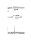
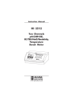
USER OPERATING MANUAL for the JACQUES DCS-550M SERIES II MASTER Publication version 2 March 2003 Jacques Electronics Pty Ltd ABN 11 010 416 323 Jacques Electronics Pty Ltd USER MANUAL - JACQUES DCS-550M SERIES 2 MASTER In case of difficulty Should a fault become apparent in the system, and simple checks have revealed nothing obvious, please follow the procedure as laid out by your internal maintenance policy. It is essential that all faults be documented in an appropriate logbook, for any future referencing. For any further information, please contact our office during business hours on any of the following numbers: Phone: 07 3844 1103 Fax: 07 3844 1078 Alternatively, contact us on the Internet: Email: [email protected] Web page: www.jacques.com.au JACQUES ELECTRONICS PTY LTD ABN 11 010 416 323 Copyright © 2003 The contents of this document may not be reproduced, stored in a retrieval system or transmitted in any form by any means; electronic, mechanical, photocopying, recording, or otherwise, without the prior written permission of Jacques Electronics Pty Ltd. Jacques Electronics Pty Ltd reserves the right to continually improve products by updating any equipment specifications, document context and design styling. Always quote this manual publication version (found on the front cover), when enquiring about any further product information. Phone: +61 7 3844 1103 Fax: +61 7 3844 1078 Email: [email protected] 268 Montague Road, West End Queensland, Brisbane, Australia 4101 Web: http://www.jacques.com.au 2 Jacques Electronics Pty Ltd USER MANUAL - JACQUES DCS-550M SERIES 2 MASTER Contents SECTION 1 – Overview The DCS-550M Series 2 Master .................................................................4 Device Identification Codes ........................................................................5 Code Types..................................................................................................5 SECTION 2 – Calling Functions Calling a JACQUES Slave ..........................................................................7 Calling a Higher-Level Master....................................................................8 Calling a Group ...........................................................................................9 SECTION 3 – Answer Functions Answering an Incoming call........................................................................11 Placing a call on Hold .................................................................................12 Monitor a call ..............................................................................................13 SECTION 4 – Menu Operations User-menus..................................................................................................14 Hidden User-menus.....................................................................................14 Menu selections...........................................................................................14 User-menu list .............................................................................................15 Saving menu selections ...............................................................................16 CPU Radio...................................................................................................17 Sys Info .......................................................................................................18 Scroll Tag List.............................................................................................19 Remote Mode ..............................................................................................20 Auto Call End..............................................................................................22 Set Date/Time..............................................................................................23 Alarm Delay ................................................................................................24 Relay Settings..............................................................................................25 Get Tags?.....................................................................................................26 Isolate Slave ................................................................................................27 Scrolling through the Isolated Slaves..........................................................28 De-Isolate Slave ..........................................................................................29 Aux Channel Set..........................................................................................30 SECTION 5 – Volume Adjustment Levels Aux Channel................................................................................................32 Call Waiting Tone .......................................................................................33 Call Connect................................................................................................34 SECTION 6 – Alarms Alarm Codes................................................................................................35 End an Alarm ..............................................................................................35 Phone: +61 7 3844 1103 Fax: +61 7 3844 1078 Email: [email protected] 268 Montague Road, West End Queensland, Brisbane, Australia 4101 Web: http://www.jacques.com.au 3 Jacques Electronics Pty Ltd USER MANUAL - JACQUES DCS-550M SERIES 2 MASTER SECTION 1 – Overview The DCS-550M Series 2 Master The Jacques DCS-550M Series 2 Master is available as either a standalone or desktop Master console. It is available as an option to the Jacques PCC-550M PC Master. FIGURE 1 shows the front panel and switch layout for the Jacques DCS-550M Series 2 Master unit. The main display comprises of a custom two lined LCD character display, sizing sixteen (16) large characters, each measuring 8mm high x 5mm wide. All user-function menus and calling information are clearly displayed on this screen. Important Note: Some of these user-function menus may not be enabled – depending on specific site installation criteria. If they are not enabled, they will not appear when you scroll through the menu list. FIGURE 1: Front panel layout of the DCS-550M Series 2 Master 5 1 2 4 3 User controls and functions: 1. Large LCD display, backlit for easy viewing 2. Sixteen user pushbuttons 3. Internal Electret Microphone 4. Eight function pushbuttons 5. Internal water-resistant speaker Phone: +61 7 3844 1103 Fax: +61 7 3844 1078 Email: [email protected] 268 Montague Road, West End Queensland, Brisbane, Australia 4101 Web: http://www.jacques.com.au 4 Jacques Electronics Pty Ltd USER MANUAL - JACQUES DCS-550M SERIES 2 MASTER SECTION 1 – Overview Device Identification Codes The DCS-550M Series 2 Master displays Identification Codes that are used to represent Devices (see FIGURE 2). Devices are attached Intercom Slaves or Accessories that make up the JACQUES Intercom System, and are individually controlled by the Master. Every JACQUES Device has to be registered within the operating software by means of Identification Codes. These codes are critical for correct Device identification and operation within the Jacques intercom system and consist of four different individual codes: FIGURE 2 Example of four codes displayed on the LCD screen are: “CELL 1” = Device Descriptor “3” = Indicates the 3rd Tag on the list “130” = Device Tag number “Slave” = Device Class type Code types 1/ Descriptor (Example: CELL 1) A Descriptor is another software address identifier code used to identify the Device. They are displayed on the LCD screen. It is text up to 16 characters long (to fit within the 16-character LCD screen size), stored inside the EEPROM memory chip located on the actual Pro Slave PCB, or inside the Concentrator unit (when using Concentrator Slaves). Descriptors are NOT changeable by the Operator and can only be changed by a Technician from the Setup menu (see separate JACQUES PC Master Technical Manual), and then only from a Jacques PCC-550M PC Master unit (usually the Highest-Level Master Station) 2/ List Tag (Example: 3) List Tag numbers, are numbers between 1 and the last Tag found in the networked intercom system. They are a counter value that simply lists the place a Tag is within the Tags list. Therefore, as you scroll through the Tags, this number will increment or decrement accordingly. Every Device has a different List Tag number. Phone: +61 7 3844 1103 Fax: +61 7 3844 1078 Email: [email protected] 268 Montague Road, West End Queensland, Brisbane, Australia 4101 Web: http://www.jacques.com.au 5 Jacques Electronics Pty Ltd USER MANUAL - JACQUES DCS-550M SERIES 2 MASTER SECTION 1 – Overview Code types (continued) 3/ Tag (Example: 130) A Tag can be described as one of the software address identifier codes, to the rest of the system. The Tag is stored inside the EEPROM memory chip, located on the actual Concentrator-type Slave PCB or inside the Concentrator unit (when using Concentrator-type Slaves). Tags are displayed on the LCD screen. . Tags are NOT changeable by the Operator and can only be changed by a Technician from the Setup menu (see separate JACQUES PC Master Technical Manual), and then only from a Jacques PCC550M PC Master unit (usually the Highest-Level Master Station) 4/ Device Class (Example: Slave) Device Class numbers, are numbers between 0 to 255 inclusive that are given to a Jacques Device. They are used to describe the type of Jacques Device that is used with that specific Tag number, described in one of the following ways: (see TABLE 1) TABLE 1 - Device Classes JACQUES ELECTRONICS DEVICE CLASSES and DISPLAYS CLASS # JACQUES DEVICE TYPES LCD DISPLAY 1 2 3 4 5 6 7 8 Any other number Slave CPU Printer Audio recorder Interface 24 way I/O card Slave Concentrator PA Amplifier Door / Gate Slave Any other Device Slave CPU Printer Recordr IO24 Concent PA Amp DoorSlv <displays CLASS #> Phone: +61 7 3844 1103 Fax: +61 7 3844 1078 Email: [email protected] 268 Montague Road, West End Queensland, Brisbane, Australia 4101 Web: http://www.jacques.com.au 6 Jacques Electronics Pty Ltd USER MANUAL - JACQUES DCS-550M SERIES 2 MASTER SECTION 2 – Calling Functions This Section covers the following key areas of calling devices: • Calling a Jacques Slave • Calling a Higher-level Jacques Master • Calling a Group Calling a JACQUES Slave Note: 1. 2. 3. There are three types of Jacques Slaves available. Mini Slaves Concentrator Slaves Door Slaves Either type of Slave can be called using the following method. However, a Door Slave can only be called when the Door Call Answer and Special functions are enabled. FIGURE 3: Calling a Slave No calls: System Idle screen: Make sure that the screen is in the System Idle mode before sending any calls. Begin a call: Press the CALL key to begin a call to a Slave. Enter the Tag number: Type in the Tag number of the Slave you wish to call. EG: Slave 1-3-1 is entered, and press the ENTER key. The call is now connected. The Operator can now hear the called Slave. Example: Slave with Tag# 131 Talk button. To SPEAK to the Slave: Press and hold down the ENTER key. Speak into the microphone, which is located inside the Master unit. To disconnect and END the Call: Press the END key to disconnect the Call and return to the System Idle screen. Phone: +61 7 3844 1103 Fax: +61 7 3844 1078 Email: [email protected] 268 Montague Road, West End Queensland, Brisbane, Australia 4101 Web: http://www.jacques.com.au 7 Jacques Electronics Pty Ltd USER MANUAL - JACQUES DCS-550M SERIES 2 MASTER SECTION 2 – Calling Functions Calling a Higher-Level Jacques Master FIGURE 4: Calling a Higher-Level Master No calls: System Idle screen: Make sure that the screen is in the System Idle mode before sending any calls. Make a call: Press the A key to place a call to the Higher-level Master. This Master is now calling the Higher-level Master, waiting for the higher Master to answer the call. When the call is answered from the Higher Master, this Master will now operate as a Slave. Therefore, there is no PTT key. The Operator can then speak into the microphone, which is located inside the Master unit. To disconnect and END the Call: Press the END key to disconnect the Call and return to the System Idle screen. Phone: +61 7 3844 1103 Fax: +61 7 3844 1078 Email: [email protected] 268 Montague Road, West End Queensland, Brisbane, Australia 4101 Web: http://www.jacques.com.au 8 Jacques Electronics Pty Ltd USER MANUAL - JACQUES DCS-550M SERIES 2 MASTER SECTION 2 – Calling Functions Calling a Group About Groups. A Group is a combination of different Jacques Devices (such as PA Amplifiers and Slaves) that are combined together to form a Group. There are up to sixteen different Groups allowed and each one can be individually selected or all at once. When a particular Group is selected, (by entering its group number between 1 and 16), all of those Jacques Devices within that Group, become active. This allows the Operator to make an announcement over a selected large area simultaneously. This is referred to as a Group-call. FIGURE 5 (see next page) shows how to make a Group call. It is important to note here, that the Master will remember the last Group call number, and will display it in the screen as a star “*”. If you want to add or delete a Group number from the last setting, you will need to do so accordingly, as shown from the FIGURE 5 (next page) diagram. …continued next page: Phone: +61 7 3844 1103 Fax: +61 7 3844 1078 Email: [email protected] 268 Montague Road, West End Queensland, Brisbane, Australia 4101 Web: http://www.jacques.com.au 9 Jacques Electronics Pty Ltd USER MANUAL - JACQUES DCS-550M SERIES 2 MASTER SECTION 2 – Calling Functions Calling a Group (continued) FIGURE 5: Calling a Group No calls: System Idle screen: Make sure that the screen is in the System Idle mode before sending any calls. Begin a Group call: Press the CALL key and then the B key to begin a Group call. Select the Group number: Enter PA Grp. --------------Select the Group number To add a call: To delete a call: Enter PA Grp. --*-----------To make a call: To end a call: The 16 dashes, “-“, indicates the 16 different groups that are available for the Operator to select from. The dash on the far left represents Group # 1. The dash on the far right represents Group # 16. They are in numerical order from left to right. NOTE: The last group(s) selected will appear on the screen as a “*” The Groups are saved in memory after every Group call. To change the groups, you may have to delete or add a Group(s). Key in the required Group number: Select the Group number by keying in that number. EG: Group 3 is entered. To delete that Group (example Group#3): Press the D key. To add that Group (example Group#3): Press the ENTER key. To call that Group: The selected Group (Group 3 example) is now confirmed by a star, “*”, replacing the dash. Press the CALL key to connect the call to the Group. The call is now connected. The Operator can now make the announcement to the PA. Talk button. To make the announcement to the PA: Press and hold down the ENTER key. Speak into the microphone, which is located inside the Master unit. To disconnect and END the Call: Press the END key to disconnect the Call and return to the System Idle screen. Phone: +61 7 3844 1103 Fax: +61 7 3844 1078 Email: [email protected] 268 Montague Road, West End Queensland, Brisbane, Australia 4101 Web: http://www.jacques.com.au 10 Jacques Electronics Pty Ltd USER MANUAL - JACQUES DCS-550M SERIES 2 MASTER SECTION 3 – Answer Functions This Section covers the following key areas of answering calls: • Answering an incoming call • Using call hold • Monitoring a call Answering an Incoming call Refer FIGURE 6. The Jacques Slave CALL button is pressed within the Networked Intercom system, initialising a call send function to the Master. The incoming call can then be answered by the operator. FIGURE 6: A Jacques Slave CALL button is pressed – a call send function is sent to the Master. The Master beeps to indicate a call is waiting. System Idle Que: 130 Incoming call is present: The screen will change to indicate the Tag number of that calling Slave. EG: 130 Answer Incoming call: Press the ENTER key to answer the incoming call. The call is now connected. CELL 1 01/01/2001 12:00 Talk button. To SPEAK to the caller: Press and hold down the ENTER key. Speak into the microphone, which is located inside the Master unit. Call display: The display changes to show the actual Tag that has been answered. EG: CELL 1 The Operator can now hear the caller from the Slave. To disconnect and END the call: ** Press the END key to disconnect the Call and return to the System Idle screen. **If there are multiple incoming calls, the END key will end the current call and display the next call in the queue. To answer that next call, press the ENTER key. Use the ENTER key to speak, use the END key to end that call. Phone: +61 7 3844 1103 Fax: +61 7 3844 1078 Email: [email protected] 268 Montague Road, West End Queensland, Brisbane, Australia 4101 Web: http://www.jacques.com.au 11 Jacques Electronics Pty Ltd USER MANUAL - JACQUES DCS-550M SERIES 2 MASTER SECTION 3 – Answer Functions Placing a call on Hold Incoming calls can be placed on Hold (they stay connected, but are not active), when other incoming calls are present. Only one call can be placed on hold at a time. FIGURE 7: Multiple incoming calls – using the call HOLD Function In this example, two Jacques Slave CALL buttons are pressed – Slaves with Tag#s 10 and 500. The Master beeps to initiate these calls are waiting to be answered. Incoming calls are present: The screen will change to indicate the Tag number of the calling Slaves. EG: 10, 500 System Idle Que: 10 500 Answer the first incoming call: Press the ENTER key to connect the first call (Slave 10). The call is now connected and is displayed as Block C CELL 2 The display shows the calls remaining in the queue and in this example are displayed as Que: 500. Block C CELL 2 Que: 500 Call on Hold: Press the HOLD key to place the active call (Slave 10) on hold. That call is now on hold and is displayed as 10 on Hold. The display shows the calls remaining in the queue and in this example are displayed as Que: 500 Block A Gate 01/01/2001 12:00 10 on Hold Que: 500 Answer the next call Press the ENTER key to answer the next call. The call is now connected and is displayed as Block A Gate Press the END key to disconnect that call. There are no other calls in the queue, but still one on Hold (from before). This is displayed as 10 on Hold 10 on Hold 01/01/2001 12:00 Press the HOLD key to re-connect that call. When finished, press the END key to disconnect. Phone: +61 7 3844 1103 Fax: +61 7 3844 1078 Email: [email protected] 268 Montague Road, West End Queensland, Brisbane, Australia 4101 Web: http://www.jacques.com.au 12 Jacques Electronics Pty Ltd USER MANUAL - JACQUES DCS-550M SERIES 2 MASTER SECTION 3 – Answer Functions Monitor a call About Monitoring A single Jacques Slave can only be monitored at one time. Slave monitoring allows the Operator to listen in to the selected Slave. FIGURE 8: Monitoring a call (from the System Idle screen) To activate the Monitor function, press the HOLD key. Monitor 01/01/2001 12:00 Example: To monitor the Slave with Tag# 131: Key in the Tag# 1-3-1 and press the ENTER key. NOTE: If nothing is heard, increase the speaker volume by using the UP key. Slave with Tag#131 is now being monitored. The Operator can hear all activity from this Slave. CELL 1:131 Slave Phone: +61 7 3844 1103 Fax: +61 7 3844 1078 Email: [email protected] 268 Montague Road, West End Queensland, Brisbane, Australia 4101 Web: http://www.jacques.com.au 13 Jacques Electronics Pty Ltd USER MANUAL - JACQUES DCS-550M SERIES 2 MASTER SECTION 4 – Menu Operations User-menus The DCS-550M Series 2 Master has an internal menu-select type operation. These menus (User-menus) are used by the Operator to setup and control all aspects of Calling operations, including enabling/disabling Remote Mode, Alarms, Radio channels, Auto Call End, etc. The User-menus are selected and used by the Operator; however, some menus can only be set by JACQUES technical staff, before the Master is shipped out to the customer. These menus are known as Hidden menus. Hidden User-menus Hidden menus are those menu functions that are not shown (hidden) within the User-menu list. These functions can only be enabled/disabled by JACQUES technical staff. Hidden menus allow the versatility of custom-made functions that specific customers require, providing the advantages of easier operation (less menus to setup and use), and the benefit to upgrade and expand later. Menu selections 1/ Press the MENU key from the System Idle screen (FIGURE 9). This will display the first Usermenu option (CPU Radio). 2/ Use the UP and DOWN arrow keys to find the menu you require. 3/ Once the correct User-menu is found, press the ENTER key to enter into that particular menu function – providing the Operator with other options for that menu function. FIGURE 9: User-menu selection from the System Idle screen To display the menus, press the MENU key from the System Idle screen. CPU Radio 01/01/2001 12:00 Then use the UP DOWN keys to scroll through the different User-menus. Press the ENTER key to enter the selected menu Channel OFF Phone: +61 7 3844 1103 Fax: +61 7 3844 1078 Email: [email protected] 268 Montague Road, West End Queensland, Brisbane, Australia 4101 Web: http://www.jacques.com.au 14 Jacques Electronics Pty Ltd USER MANUAL - JACQUES DCS-550M SERIES 2 MASTER SECTION 4 – Menu Operations Important Note: Some of the function menus shown here in the User-menu list MAY NOT BE ENABLED on your DCS-550M Master. If they are not enabled, they will not appear when you scroll through the menu list and are known as “Hidden-menus”. Refer to JACQUES for more details. User-Menu list CPU Radio This menu switches ON or OFF the two Auxiliary audio channels, which can be heard through the DCS-550M Master’s internal speaker. Sys Info This menu shows the current Master version software loaded and the Master controller version that it is connected to. Scroll Tag List This menu displays all current and active Tags (Slaves, Masters and other Devices) that are connected to the Master. This is a viewer only function and no changes can be made to the Tags from this menu. Remote Mode This menu enables or disables the Remote mode. Once in Remote mode, the Master is completely controlled by the next Higher-Level Master. All incoming calls will then be diverted to that Higher-Level Master, after a selection of preset times. Auto Call End This menu is used to set the time that a call will automatically end, if no further call activity is detected. Set Date/Time This menu allows the operator to change the RTC’s Time and Date locally. However, the time and date will automatically be updated from a Higher-level Master (if used). Alarm Delay This menu is used to set the properties of the “Tamper Alarm” and “Button Stuck” features that are built into the JACQUES RS485 Slaves. Relay Settings This menu is used to activate the Relay switching properties, located on the Slaves. Get Tags? This menu allows the operator to get Tag, Descriptor and Class ID information from the connected Devices within the Intercom System. Isolate / De-Isolate Slave This menu allows the operator to Disable or Isolate selected Slaves from the intercom system. When a Slave is Isolated, it is effectively disabled from the system, until it is Enabled again (De-Isolate) from this same menu. Aux Channel Set This menu allows the operator to change the individual Auxiliary audio channels and speaker volume levels of connected JACQUES Slaves. Phone: +61 7 3844 1103 Fax: +61 7 3844 1078 Email: [email protected] 268 Montague Road, West End Queensland, Brisbane, Australia 4101 Web: http://www.jacques.com.au 15 Jacques Electronics Pty Ltd USER MANUAL - JACQUES DCS-550M SERIES 2 MASTER SECTION 4 – Menu Operations Saving menu selections Some menus require the operator to select one of a multiple choice function list. They are: • CPU Radio • Remote Mode • Auto Call End Once selected, that option needs to be saved. The options from these menus are all very important, as they determine specific power-on functions. See these individual menus, for specific menu options. These individual settings can be saved by pressing the MENU key and then the A key (FIGURE 10) FIGURE 10: Saving your settings. Select your preferred settings from the individual menus. Press MENU key Press A key Your settings have now been saved and will not need to be reprogrammed the next time this console is re powered. Press END to return to the System Idle screen. System Idle screen Phone: +61 7 3844 1103 Fax: +61 7 3844 1078 Email: [email protected] 268 Montague Road, West End Queensland, Brisbane, Australia 4101 Web: http://www.jacques.com.au 16 Jacques Electronics Pty Ltd USER MANUAL - JACQUES DCS-550M SERIES 2 MASTER SECTION 4 – Menu Operations CPU Radio The CPU Radio menu (FIGURE 11) is used to change the two different Auxiliary audio channels. These audio channels can be heard through the internal speaker of the Master. By using the UP and DOWN keys, the operator can select between enabling Auxiliary audio channel 1, Auxiliary audio channel 2, or no channels (both channels off – no audio). Once selected, press the ENTER key to save the selection and then press the END key to return back to the System Idle screen. NOTE: If your selection cannot be heard, press the UP key to adjust the channel volume. FIGURE 11: CPU Radio menu option Use the UP DOWN keys to select the CPU Radio menu option. Press ENTER to begin. CPU Radio 01/01/2001 12:00 Press the END key to return to the System Idle screen. Channel Off (Both audio channels off – no audio). Channel Off Channel 1 Use the UP DOWN keys to scroll through the choices. Channel 2 Press the ENTER key to save the setting and return to the CPU Radio screen. Phone: +61 7 3844 1103 Fax: +61 7 3844 1078 Email: [email protected] 268 Montague Road, West End Queensland, Brisbane, Australia 4101 Web: http://www.jacques.com.au 17 Jacques Electronics Pty Ltd USER MANUAL - JACQUES DCS-550M SERIES 2 MASTER SECTION 4 – Menu Operations Sys Info The Sys Info menu (FIGURE 12) shows the current Master version software loaded as well as the Master controller version used. This is used to identify current operating software versions. Example of Sys Info screen display. Yours may be different, due to software upgrades. FIGURE 12: Sys Info menu option Use the UP DOWN keys to select the Sys Info menu option. Press ENTER to begin. Sys Info 01/01/2001 12:00 Display shows Master console version, as well as Master controller version Console 1.00 Master 2.2.83 Press the END key to return to the System Idle screen. Phone: +61 7 3844 1103 Fax: +61 7 3844 1078 Email: [email protected] 268 Montague Road, West End Queensland, Brisbane, Australia 4101 Web: http://www.jacques.com.au 18 Jacques Electronics Pty Ltd USER MANUAL - JACQUES DCS-550M SERIES 2 MASTER SECTION 4 – Menu Operations Scroll Tag List The Scroll Tag List menu (FIGURE 13) is used to view all Slaves, Masters and other Devices that are connected to the Master unit. This menu functions as a viewer only and NO changes can be made to the Tags. Once in the Scroll Tag List menu, the operator can scroll through the Devices by using the UP and DOWN keys. Press the END key to return to the Scroll Tag List screen. Press the END key (again) to return to the System Idle screen. FIGURE 13: Scroll Tag List menu option. Use the UP DOWN keys to select the Scroll Tag List menu option. Press ENTER to begin. Scroll Tag List 01/01/2001 12:00 Press the END key to return to the System Idle screen. Use the UP, DOWN keys to scroll through the Tags. L1 MASTER 1:2 CPU Examples only. Actual content will be different to yours. L2 MASTER 2:32 CPU CELL 1 3:131 Slave Press the END key to return to the Scroll Tag List screen. Phone: +61 7 3844 1103 Fax: +61 7 3844 1078 Email: [email protected] 268 Montague Road, West End Queensland, Brisbane, Australia 4101 Web: http://www.jacques.com.au 19 Jacques Electronics Pty Ltd USER MANUAL - JACQUES DCS-550M SERIES 2 MASTER SECTION 4 – Menu Operations Remote Mode In a multi-Master intercom system, there may be times when a Master station will be left unattended, leaving some incoming calls unanswered. The Remote Mode menu (FIGURE 14) allows the choice of those incoming unanswered calls to (after a preset time has passed) be automatically diverted to the next higher-level Master. When first switched on, the Master will either automatically go into either remote or idle modes, depending on the options saved by the operator. For more information about remoting, see next page. • When the Master is first turned on, it will either automatically go into either remote or idle modes, • • • • depending on the options saved by the operator. Press the REM or END key to turn-off the remote function (if enabled). To disable the remote function completely, select Disable REM Key option from the menu selection. To otherwise enable the remote function, press the REM key. The AutoRem 10 min, AutoRem 2 min and AutoRem 12 sec, menu options are selected as the amount of time that passes on an unanswered incoming call, before the Master automatically goes into remote mode. FIGURE 14: Remote Mode menu option. Use the UP DOWN keys to select the Remote Mode menu option. Press ENTER to begin. Remote Mode 01/01/2001 12:00 Press the END key to return to the System Idle screen. Use the UP, DOWN keys to select the following different selections These settings determine the amount of time that passes on an unanswered incoming call, before the Master automatically goes into remote mode. Disable AutoRem will disable this function. Disable REM key This setting is used to disable the REM key on the front panel of the Master, stopping the operator to turn-on/off the remote function. Disable AutoRem AutoRem 10 min AutoRem 2 min AutoRem 12 sec Press the ENTER key to save the setting and return to the Remote Mode screen. Phone: +61 7 3844 1103 Fax: +61 7 3844 1078 Email: [email protected] 268 Montague Road, West End Queensland, Brisbane, Australia 4101 Web: http://www.jacques.com.au 20 Jacques Electronics Pty Ltd USER MANUAL - JACQUES DCS-550M SERIES 2 MASTER SECTION 4 – Menu Operations Remote Mode (continued) In a multi-Master intercom system and a Master is remoted, then that Master’s operations are no longer controlled by the operator. The calling operations are now effectively disabled. All Slaves and Devices are all now controlled from the next-level up Master. The following diagrams illustrates this. FIGURE 15 shows the operators signal path between three level Masters, all are in Remote Off mode. This allows all three Masters to individually operate and control its own level Slaves and Devices. FIGURE 16 shows the new operators signal path between the same Masters, however the Level 2 Master is now in Remote On mode. The operators signal path has now changed. Level 3 Master now controls Level 3 Slaves and Devices (as before) as well as all of Level 2 Slaves and Devices (because Level 2 is in Remote On mode). Level 1 Master still controls Level 1 Slaves and Devices (as before). FIGURE 15 FIGURE 16 Phone: +61 7 3844 1103 Fax: +61 7 3844 1078 Email: [email protected] 268 Montague Road, West End Queensland, Brisbane, Australia 4101 Web: http://www.jacques.com.au 21 Jacques Electronics Pty Ltd USER MANUAL - JACQUES DCS-550M SERIES 2 MASTER SECTION 4 – Menu Operations Auto Call End The Auto Call End menu (FIGURE 17) is used to automatically disconnect an already connected call. It disconnects after a preset time has passed and that there is no call activity detected. FIGURE 17: Auto Call End menu option. Use the UP DOWN keys to select the Auto Call End menu option. Press ENTER to begin. Auto Call End 01/01/2001 12:00 Press the END key to return to the System Idle screen. Use the UP, DOWN keys to select the following different selections Disable AutoEnd AutoEnd 2 min AutoEnd 10 min AutoEnd 30 min These settings determine the amount of time that passes on an already connected call, before the Master automatically disconnects that call. Disable AutoEnd will disable this function. Press the ENTER key to save the setting and return to the Auto Call End screen. Phone: +61 7 3844 1103 Fax: +61 7 3844 1078 Email: [email protected] 268 Montague Road, West End Queensland, Brisbane, Australia 4101 Web: http://www.jacques.com.au 22 Jacques Electronics Pty Ltd USER MANUAL - JACQUES DCS-550M SERIES 2 MASTER SECTION 4 – Menu Operations Set Date/Time The date and time is maintained by an internal clock. The clock has a backup battery that can maintain correct time for 3 or 4 days without power. FIGURE 18: Set Date/Time menu option. (set from the Highest-Level Master) Use the UP DOWN keys to select the Set Date/Time menu option. Press ENTER to begin. Set Date/Time 01/01/2001 12:00 Press the END key to return to the System Idle screen. Use the UP, DOWN keys to select the following different selections of: Seconds, Minutes, Hours, Year, Month and Day. New Date & Time 01/01/2001 12:0X New Date & Time 01/01/2001 12:X0 New Date & Time X1/01/2001 12:00 Save the correct time by pressing the A key. Press the END key to exit back to the main menu. Phone: +61 7 3844 1103 Fax: +61 7 3844 1078 Email: [email protected] 268 Montague Road, West End Queensland, Brisbane, Australia 4101 Web: http://www.jacques.com.au 23 Jacques Electronics Pty Ltd USER MANUAL - JACQUES DCS-550M SERIES 2 MASTER SECTION 4 – Menu Operations Alarm Delay The Alarm Delay menu is used to set the properties of the “Tamper Alarm” and “Button Stuck” features that are built into the JACQUES RS485 Slaves. See FIGURE 19 below for changing the Alarm Delay properties. Note: These Alarm features are only found with the JACQUES RS485 Slaves. • The Tamper Alarm feature is used to alert the Operator on the Master display screen, that a Slave has been pulled out of its mounting. • The Button Stuck feature is used to alert the Operator on the Master display screen, that a Slave has a jammed Call button pushed in. FIGURE 19: The Alarm Delay menu selects the Tamper and Button Stuck Alarm options. Use the UP DOWN keys to select the Alarm Delay menu option. Press ENTER to begin. Alarm Delay 01/01/2001 12:00 Press the END key to return to the System Idle screen. Use the UP, DOWN keys to select the different options. Disable Alarm These Delay settings determine the amount of time that passes on a valid Alarm message to be resent to the Master, IF the Alarm is not cleared. EG: - Slave produces an Alarm. - Slave sends Alarm message to Master - Master displays Alarm - Operator clears Alarm on Master - x minutes later, the Alarm message will reappear at the Master, IF the Alarm is not cleared at the Slave. The Disable Alarm setting is used to completely disable the Alarm function. (The Master will not display any Alarm messages at all). 20min. Delay 10min.Delay 2min.Delay Press the ENTER key to save the setting and return to the Alarm Delay screen. No Delay The No Delay setting will allow predetermined Delay times on Alarm messages sent from the Slaves. Button Stuck = every 2 minutes, Tamper = every 20 seconds Phone: +61 7 3844 1103 Fax: +61 7 3844 1078 Email: [email protected] 268 Montague Road, West End Queensland, Brisbane, Australia 4101 Web: http://www.jacques.com.au 24 Jacques Electronics Pty Ltd USER MANUAL - JACQUES DCS-550M SERIES 2 MASTER SECTION 4 – Menu Operations Relay Settings The DCS-550M Master can switch up to two individual Relays, which are located on the Slave Stations. The relays need to have been correctly initialised from the Relay Settings menu (see separate Jacques DCS-550M Technical Manual). Note: The Slave Station Relays can only be energized during a Call Connection. Connect the Call 1/ CALL button is pressed on a Slave. (The Relays are installed on the Slave PCB) 2/ The DCS-550M Master answers the call by pressing the ENTER key. The Call is now connected. As soon as the Call is connected, the Slave Relays can be activated. Activation of the Slave Relays Default relay ON time setting: The default Relay energise ON time is set to 1 second. This means that each relay will automatically energise on the Slave Station for 1 second, when a Call is connected. Changed relay ON time settings: The energise ON time for the relays can be changed from the Relay Settings menu. (see separate Jacques DCS-550M Technical Manual). If these settings have changed, then the following rules apply: If the relay ON time = 0s (0 seconds), then; • Press the A key. Relay 1will energise • Press the B key. Relay 2 will energise • Ending the Call will de-energise the Relay. If the relay ON time > 0s (> 0 seconds), then; • Relay 1 will energise, as per Relay Settings menu. (see separate Jacques DCS-550M Technical Manual) • Relay 2 will energise, as per Relay Settings menu. (see separate Jacques DCS-550M Technical Manual). • Relay will de-energise, after the ON time = xxs setting has expired End Call function The End Call function (if enabled) will energise a Relay on the Slave Station for xx seconds, and then automatically End the call. (See separate Jacques DCS-550M Technical Manual). Default End Call setting: The default End Call setting is NO. This means that this function is disabled. Phone: +61 7 3844 1103 Fax: +61 7 3844 1078 Email: [email protected] 268 Montague Road, West End Queensland, Brisbane, Australia 4101 Web: http://www.jacques.com.au 25 Jacques Electronics Pty Ltd USER MANUAL - JACQUES DCS-550M SERIES 2 MASTER SECTION 4 – Menu Operations Get Tags? In a finished Intercom System, the Master needs to find and validate all of the connected Devices, Tags and Class ID. This process needs doing only the once and then every time a new Device is added to the Intercom System. The following FIGURE 20 shows how the DCS-550M Master finds the attached Devices. When it finds a Device, it then records its individual Tag, Descriptor and Class ID and stores this information into its own internal Flash ROM. This provides a database of all the Devices and Tags found within the Intercom System. FIGURE 20: The following Get Tags procedure needs to be done when the Intercom System is first commissioned and then every time a new Device is added to the Intercom System. Use the UP DOWN keys to select the Get Tags menu option. Press ENTER to begin. Press the END key to return to the System Idle screen. Get Tags ? (1=Yes, *=No) Press the 1 key to Get the Tags. Press the * key to Abort and Exit. The Master begins to search all of the Tags and Descriptors in the Intercom System Requesting Tags xx Tag(s) Found Save Tags ? (1=Yes, *=No) x Tags Saved Any key to exit Req Descriptors Press the 1 key to Save the Tags. Press the * key to Abort and Exit. All of the Devices Tags, Descriptors and Class ID’s have now been saved into the Flash ROM, located inside the Master. Press any key to Exit. Phone: +61 7 3844 1103 Fax: +61 7 3844 1078 Email: [email protected] 268 Montague Road, West End Queensland, Brisbane, Australia 4101 Web: http://www.jacques.com.au 26 Jacques Electronics Pty Ltd USER MANUAL - JACQUES DCS-550M SERIES 2 MASTER SECTION 4 – Menu Operations Isolate Slave The Isolate Slave menu (FIGURE 21) is used to allow the operator to disable or isolate selected Slaves within an intercom system. When a Slave is isolated, it is effectively disabled from the system, until it is re-enabled from this same menu (see next page). A Slave may need to be isolated if for example, a Cell or room is empty, or if the Slave is faulty or damaged. FIGURE 21: Isolate Slave menu option. Use the UP DOWN keys to select the Isolate Slave menu option. Press ENTER to begin. Isolate Slave 01/01/2001 12:00 Press the END key to return to the System Idle screen. In order to isolate a particular Slave, that Slave’s Tag number must be entered at the Isolate menu, followed by the ENTER key. Any number of Tags can be entered here. Isolate Example: Isolate Tag# 3 Example: Isolate Tag# 131 Press the END key to return to the Isolate Slave screen. Phone: +61 7 3844 1103 Fax: +61 7 3844 1078 Email: [email protected] 268 Montague Road, West End Queensland, Brisbane, Australia 4101 Web: http://www.jacques.com.au 27 Jacques Electronics Pty Ltd USER MANUAL - JACQUES DCS-550M SERIES 2 MASTER SECTION 4 – Menu Operations Isolate Slave (continued) Scrolling through the Isolated Slaves If ISO is displayed on the top right-hand side of the System Idle screen (FIGURE 22), it indicates that there are one or more Slaves already isolated. To quickly view these isolated Slaves, go to the Isolate Slave menu and then press the ENTER key. Scroll through the isolated Slaves by using the UP and DOWN keys. FIGURE 22: ISO is displayed on the top right of the System Idle screen. ISO. Use the UP DOWN keys to select the Isolate Slave menu option. Press ENTER to begin. Isolate Slave 01/01/2001 12:00 Press the END key to return to the System Idle screen. Isolate Example: Scroll to 2nd Isolated Slave, Tag# 3 Cell 1 2:3 Slave Press the END key to return to the Isolate Slave screen. L1 EXIT 1:131 Slave Use the UP DOWN keys to scroll through the Isolated Slaves Example: Scroll to 1st Isolated Slave, Tag# 131 Phone: +61 7 3844 1103 Fax: +61 7 3844 1078 Email: [email protected] 268 Montague Road, West End Queensland, Brisbane, Australia 4101 Web: http://www.jacques.com.au 28 Jacques Electronics Pty Ltd USER MANUAL - JACQUES DCS-550M SERIES 2 MASTER SECTION 4 – Menu Operations Isolate Slave (continued) De-Isolate Slaves If ISO is displayed on the top right-hand side of the System Idle screen (FIGURE 23), it indicates that there are one or more Slaves already isolated. At some time, those Slaves will need to be deisolated to bring them back online into the intercom system. To De-Isolate these Slaves, use the same procedure as the Isolate Slave function, except that the Slave’s Tag number must be followed by a “D” key, instead of “ENTER”. FIGURE 23: De-Isolate Slave menu option. ISO. Use the UP DOWN keys to select the Isolate Slave menu option. Press ENTER to begin. Isolate Slave 01/01/2001 12:00 Press the END key to return to the System Idle screen. In order to De-Isolate a particular Slave, that Slave’s Tag number must be entered at the Isolate menu, followed by the D key. Isolate Any number of Tags can be entered here. Example: De-Isolate Tag# 3 Example: De-Isolate Tag# 131 Press the END key to return to the Isolate Slave screen. Phone: +61 7 3844 1103 Fax: +61 7 3844 1078 Email: [email protected] 268 Montague Road, West End Queensland, Brisbane, Australia 4101 Web: http://www.jacques.com.au 29 Jacques Electronics Pty Ltd USER MANUAL - JACQUES DCS-550M SERIES 2 MASTER SECTION 4 – Menu Operations Aux Channel Set The Aux Channel Set menu (FIGURE 24) is used to allow the operator to change the auxiliary audio channel number and volume level, for any connected Slaves, directly from the Master. About Auxiliary audio channels: There are two auxiliary audio channels present within the Jacques Intercom system. Usually one channel will be connected to a radio tuner and the other to another audio source such as a CD player. These two audio channels can each be individually activated and controlled via the Aux Channel Set menu. The audio from the Aux audio channels are heard through the individual Slaves speakers. The Aux Channel Set menu is used to set the audio channels and individual volume levels. It is noted here that even once these levels are set from the Master, the Slave can still override these settings if that Slave has separate Volume and Aux select buttons. FIGURE 24: Aux Channel Set menu option. Use the UP DOWN keys to select the Aux Channel Set menu option. Press ENTER to begin. Aux Channel Set 01/01/2001 12:00 Press the END key to return to the System Idle screen. Slave? Select the Slave to be changed by either one of two ways: Key in the correct Tag number of the Slave (eg: 5678) and then press the ANSWER key. Scroll through the tag list by using the UP and DOWN keys and then press the ANSWER key. The display changes to: Slave: 5678 Ch=1 Vol=5 …continued next page: Phone: +61 7 3844 1103 Fax: +61 7 3844 1078 Email: [email protected] 268 Montague Road, West End Queensland, Brisbane, Australia 4101 Web: http://www.jacques.com.au 30 Jacques Electronics Pty Ltd USER MANUAL - JACQUES DCS-550M SERIES 2 MASTER SECTION 4 – Menu Operations Aux Channel Set (continued) Slave: 5678 Ch=1 Vol=5 Slave: 5678 is the selected Slave’s Tag number. Ch=1 is the current channel selection value. Channels can have one of four values, they are: • “OFF” - There are no auxiliary audio channels selected. When this is set, the volume selection disappears from the screen. • “1” – Auxiliary audio channel number 1 has been selected. • “2” - Auxiliary audio channel number 2 has been selected. • “3” – This is reserved for future use. Vol=5 is the current volume level value. Volume levels can have one of eight values, they are: • “0” – no volume or speaker mute. • “1”, “2”, “3”, “4”, “5”, “6”, “7” – Slave speaker volume levels. Level 1 is the softest level, Level 7 is the loudest level. To change the settings: The Ch=? and Vol=? Values can be changed in this screen. • • • Use the star “*” key to toggle between these two values. Use the UP and DOWN keys to change the values. Once the values have been correctly entered, press the ANSWER key to save these changes. The display will show your new values for 3 seconds, before it goes back into Slave selection screen: Slave selection screen: Slave? The top line displays the tag number of the Slave last used. You can either press the ANSWER key to edit the same Slave (in case you made a mistake before), or enter a new Tag number as before. Tag numbers can be in the range from 1 to 8191. If you enter number “9999”, the selected channel number and volume level will apply to all local intercoms. To exit and save all changes, press the END key. Phone: +61 7 3844 1103 Fax: +61 7 3844 1078 Email: [email protected] 268 Montague Road, West End Queensland, Brisbane, Australia 4101 Web: http://www.jacques.com.au 31 Jacques Electronics Pty Ltd USER MANUAL - JACQUES DCS-550M SERIES 2 MASTER SECTION 5 –Volume Adjustment Levels Aux Channel During the System Idle operation (no calls), the Master console plays the selected Auxiliary Audio Channel through its internal speaker. The Auxiliary Audio Channel volume level, or Aux. Vol, can be adjusted accordingly by the Operator. Note: The Auxiliary Audio Channel volume level can ONLY be adjusted during the System Idle screen (no calls). FIGURE 25: From the System Idle screen, press the UP, DOWN keys to increment, and decrement the volume level in steps of four. System Idle screen. Use the UP, DOWN keys to adjust the Auxiliary volume levels The Auxiliary volume is adjusted in steps of four. “0” value is no volume, or speaker mute. “64” is the maximum value. During the adjustment, the display changes to the Aux. Vol volume adjustment screen: System Idle Aux. Vol. 16 After three seconds of setting the new value, the display will return to the System Idle screen. Phone: +61 7 3844 1103 Fax: +61 7 3844 1078 Email: [email protected] 268 Montague Road, West End Queensland, Brisbane, Australia 4101 Web: http://www.jacques.com.au 32 Jacques Electronics Pty Ltd USER MANUAL - JACQUES DCS-550M SERIES 2 MASTER SECTION 5 –Volume Adjustment Levels Call Waiting Tone During an incoming call, the Master console plays a two-tone sound through its internal speaker. This is known as the Call-Waiting tone. The Call-Waiting tone volume level, or Beep Level, can be adjusted accordingly by the Operator. Note: The Call-Waiting tone volume level can ONLY be adjusted during an Incoming Call (Call-Waiting). FIGURE 26: When an incoming call is present, press the B, C keys to increment, and decrement the volume level in steps of four. Incoming Call is present: The screen will change to indicate the Tag number of that calling Slave. EG: 130 System Idle Que: 130 The Call-Waiting tone volume level can now be adjusted. Use the B, C keys to adjust the Call-Waiting tone volume level. B key to increment volume C key to decrement volume The Call-Waiting volume level is adjusted in steps of four. “0” value is no volume, or speaker mute. “64” is the maximum value. During the adjustment, the display changes to the Beep Level volume adjustment screen: System Idle Beep Level. 16 The Beep Level volume adjustment screen will disappear, after the Call has been answered. Phone: +61 7 3844 1103 Fax: +61 7 3844 1078 Email: [email protected] 268 Montague Road, West End Queensland, Brisbane, Australia 4101 Web: http://www.jacques.com.au 33 Jacques Electronics Pty Ltd USER MANUAL - JACQUES DCS-550M SERIES 2 MASTER SECTION 5 –Volume Adjustment Levels Call Connect When the incoming call has been answered by the Master, (known as Call-Connected), the Master console plays the Caller through its internal speaker. The Call-Connected volume level, or Call. Vol can be adjusted accordingly by the Operator. Note: The Call-Connected volume level can ONLY be adjusted once the incoming call has been connected. FIGURE 27: When the incoming call has been connected, press the UP, DOWN keys to increment, and decrement the volume level in steps of four. Call-Connected screen. (Call has been answered) CELL 1 01/01.2001 12:00 Use the UP, DOWN keys to adjust the Call-Connected volume levels The Call-Connected volume can be adjusted in steps of four. “0” value is no volume, or speaker mute. “64” is the maximum value. During the adjustment, the display changes to the Call Vol volume adjustment screen: CELL 1 Call Vol. 16 The Call Vol volume adjustment screen will disappear, when the key (UP, DOWN) has been released. Phone: +61 7 3844 1103 Fax: +61 7 3844 1078 Email: [email protected] 268 Montague Road, West End Queensland, Brisbane, Australia 4101 Web: http://www.jacques.com.au 34 Jacques Electronics Pty Ltd USER MANUAL - JACQUES DCS-550M SERIES 2 MASTER SECTION 6 – Alarms The DCS-550M Series 2 Master constantly monitors all operations and connected Devices for any signs of failures or disconnections. Upon sensing an error, the Master will sound an alarm and display the relevant fault description on the LCD screen. Alarm Codes The following table (TABLE 2) shows the current list of Alarm codes that are displayed during a failure of any connected Devices. The LCD screen displays the Tag# and then the relevant fault code of the faulty Device. TABLE 2 - Alarm Codes ALARM TYPES AND DISPLAYED CODES ALARM TYPES An Alarm will sound if… Any connected Devices (Slaves, Masters, etc) are not responding or goes offline Any connected (Concentrator-type) Slave has been tampered with Any connected Slave has a stuck CALL-button (or CALL-button has been pressed for longer than 4 seconds) An unknown Tag (Device) has been found The Remote CPU (Controller) has failed, or it cannot Remote switch The audio path between any connected Slave’s Speaker and Microphone has failed Whenever a Lower Master has been RemoteSwitched (Remoted) FAULT CODES Shows Tag# and…” “ Offline Tamper BtnFail Unknown RemFail MicFail CPU Remote End an Alarm If an Alarm is displayed, the Operator can quickly stop and reset it by pressing the END key. Example: FIGURE 28: Tag# “1004” (a Slave) has a failed microphone, which quickly prompts the following MicFail Alarm message: 1004 MicFail Press the END key to clear the Alarm message Phone: +61 7 3844 1103 Fax: +61 7 3844 1078 Email: [email protected] 268 Montague Road, West End Queensland, Brisbane, Australia 4101 Web: http://www.jacques.com.au 35 Jacques Electronics Pty Ltd USER MANUAL - JACQUES DCS-550M SERIES 2 MASTER For further details about JACQUES Intercom features and designs, please visit the JACQUES website at: www.jacques.com.au copyright 2002 JACQUES ELECTRONICS Pty Ltd Jacques Electronics Pty Ltd reserves the right to continually improve products by updating any equipment specifications, document context and design styling and then passing this information onto this document. Phone: +61 7 3844 1103 Fax: +61 7 3844 1078 Email: [email protected] 268 Montague Road, West End Queensland, Brisbane, Australia 4101 Web: http://www.jacques.com.au 36