1
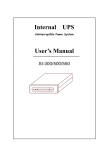
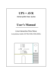
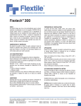
Top view
2
Side view
2,5m
1
Minilux Sensor PIR 360° Wireless
41-380
C
D
A BCD
D
ø2
3m2
ø3,4
9m2
ø8
50m2
ø13,5
140m2
ø3
ø5
ø12
ø20
127
D
ø3
7m2
ø5
19m2
ø12
110m2
ø20
300m2
0,8m
A B
C B A B C
D
A
7m2
B
19m2
C
110m2
D
300m2
3
A
A+B+C
180°
315°
Advarsel: Indbygning og montering af elektriske apparater må
kun foretages af aut. elinstallatør.
Ved fejl eller driftforstyrelser kontakt den aut. elinstallatør.
! Ret til ændringer forbeholdes !
Warning: Installation and assembly of electrical equipment
must be carried out by qualified electricians.
Contact a qualified electrician in the event of fault or breakdown.
! Reserving the right to make changes !
41Y380_03_R0_090116KOE1211
Achtung: Einbau und Montage elektrischer Geräte dürfen nur
durch Elektrofachkräfte erfolgen.
Wenden Sie sich bei Störungen bzw. Ausfall an einen Elektrofachkraft.
! Änderungen vorbehalten !
Avertissement : L’installation et le montage d’appareils
électriques doivent exclusivement être exécutés par un
électricien agréé.
En cas de défaut ou de perturbation du fonctionnement,
contacter un installateur électricien agréé.
! Sous réserve de modifications !
Servodan A/S • DK-6400 Sønderborg
Tel.: +45 7442 4726 • Fax: +45 7442 4035
www.servodan.dk • E-mail: [email protected]
1(10)
4A
4B
4C
230Vac
L
N
8
60 mm
24Vac / DC
-+
L
230Vac
N
24Vac / DC
-+
Pozidriv (PZ) 0 /
Phillips (PH) 1
5
7
230Vac
L
N
24Vac / DC
-+
230Vac
L
N
9A
24Vac / DC
-+
LED1
230Vac
LED2
LRN LED3
Sensor PIR 360°
LED1 = Light + Movement
LED2 = Movement
LED3 = RF - Transmit
Metal
Ra
230Vac
L
N
L
230Vac
N
Factory settings
24Vac / DC
-+
24Vac / DC
-+
dio
sh
o
ad
w
Receiver
Receiver
Visual contact
9B
24Vac / DC
ON
Factory settings
OFF
DIP 1 2 3 4
A) LUX - Test mode
41-380
41-380
6
DIP settings:
PIR
PIR
24Vac / DC
230V ac
L
N
1
2
= ON position
3
4
5
6
1
2
3
4
--
+
5
6
B) PIR - Test mode
Sensor PIR 360°
Effective wall
thickness:
20 cm
C) LED1/2 ON
Effective wall
thickness:
60 cm
D) Min. sensitivity
= OFF position
Low
attenuation
D) Low sensitivity
D) High sensitivity
L
+
N
--
Receiver
High
attenuation
Receiver
D) Max. sensitivity
2(10)
GB
Minilux Sensor PIR 360° Wireless 41-380
Fitting and operating instructions
General:
The Minilux Sensor PIR 360° 41-380 is a movement
sensor based on wireless technology that sends an
RF telegram to a receiver module, which switches
the light on and off.
1st priority: Daylight
2nd priority: Movement
·
·
·
·
·
·
·
Areas of application:
Small offices
Open-plan offices divided into workgroups
Premises with rest areas
Shared activity rooms
Changing rooms
Large storage rooms
Function:
The integrated light sensor measures the light level
in the area continuously, and compares it with the
preset value specified via the LUX setting button.
If the light level falls below the preset value and the
movement sensor detects activity in the coverage area,
the light is switched on. The integrated cut-out delay of
1...30 mins (adjustable) makes sure that RF switch-on
telegrams are sent continuously (approx. once a
minute) to the receiver, until the sensor does not
register activity or the selected light level is reached.
1
Coverage area:
The movement sensor is designed to be fitted to a
ceiling. At a height of 2.5 metres the sensor will cover
a floor area with a diameter of 20 m and provide full
360° coverage for movement of people. The sensor
has a special lens area in the centre with a diameter
of 5 metres, with more than 618 fields guaranteeing
optimal detection of even very slight movements.
The movement sensor is designed to be fitted to a
ceiling at a standard height of 2.5 - 3.0 m, and is
positioned over a desk, typically 1 m away from the
seat. The sensor has a specially developed optical
function with two detection ranges, a close range (A
+ B) to detect small movements and a distant range
(C + D) to detect movement of people. This
combination provides excellent control of lighting,
while at the same time guaranteeing the best
possible energy saving.
2
Limiting the detection range:
f) 24VDC or ac is connected via the terminals
labelled: -24V and +24V.
If the coverage area is too large, it can be limited by
fitting the enclosed cover. This enables the maximum
range of 20 metres to be reduced to 12 metres, 5
metres or 3 metres in radius, and the angle of 360°
can be reduced in increments of 45°.
g) Power up causes an RF switch-on telegram to besent. The integrated indicator LED1 red or LED2
green will always be lit for 1 minute (stabilisation time).
6 Connection chart:
3
A 230Vac or a 24Vac/DC power supply is one option.
This means that both may not be connected.
Caution!:
It is recommended that the PIR Sensor is not
installed where it is exposed to direct sunlight, air
flows from air conditioning, radiators, etc. With a view
to achieving optimal transmission of the RF signal to
the receiver, the PIR Sensor should not be fitted to
premises with metal screening, which blocks signals
between transmitter and receiver, please see the
section on RF wireless information.
4
Installation:
a) The ideal measurement of daylight is obtained by
positioning the movement sensor with the light
sensor facing the source of daylight.
b) If the movement sensor is fitted directly to the
ceiling, holes at intervals of 105 mm can be
used. Please note that the cable input is turned
45° in relation to the fixing holes.
c) If the movement sensor is fitted to a ceiling box, the
holes located for this purpose at intervals of 60 mm
are used, and the base opening is punched out.
d) Neverfit the movement sensor to a metal panel,
as this reduces the RF signal dramatically.
5
Connection:
a) First read the WHOLE installation and user manual.
b) Switch off all power during installation and setup.
c) Note that the movement sensor can be connected
to EITHER 230Vac OR 24Vac/DC.
d) All assembly/cable laying must be undertaken
correctly in accordance with the prevailing
Installation Regulations.
e) 230Vac is connected via the terminals labelled:
L, N and the protective conductor to
.
7 Setting up/testing:
The movement sensor is supplied with two test mode
functions, one for a LUX test a) and for a PIR test b).
The chosen function is indicated with 2 LEDs, LED1
red for 1st priority: daylight or LED2 green to indicate
PIR activity, as the only priority. LED1 and 2 –
indication c). PIR sensitivity setting d) can be set in
4 different sensitivity positions.
LRN button is a wireless system coding for the
receiver, LED3 yellow indicates RF signal.
By the means of the LUX setting daylight blocking
can be deselected.
LED1 red indicates 1st priority: daylight and PIR
activation (Light + Movement).
LED2 green indicates the only priority is movement
and PIR activation (Movement).
LED3 yellow indicates that the RF signal is being
transmitted to the receiver.
a) LUX TEST mode.
Set the switches to DIP1 ON and DIP2 ON.
In this position an RF switch off telegram is transmitted
to the receiver module. Turn the LUX setting slowly
from min. towards max. until the integrated indicator
LED1 red lights up. At this point the LUX setting is
identical to the daylight level measured by the sensor. If
the daylight level in the room is sufficient, turn the LUX
setting towards minimum until the LED is switched off,
and leave the LUX setting at this level.
If the LUX setting is turned towards min., the lighting is
switched off at a lower daylight level.
If the LUX setting is turned towards max., the lighting is
switched off at a higher daylight level.
Finish by setting the switches to DIP1 OFF and DIP2 OFF.
b) PIR TEST mode.
Set the switches to DIP1 OFF and DIP2 ON.
In this position an RF switch-on telegram is transmitted
immediately upon PIR activation and an RF switch-off
telegram after 5 seconds, if there is no new activation.
PIR activation is indicated via the integrated indicator
LED1 red or LED2 green.
PS: In this test the daylight blocking will not be working.
Finish by setting the switches to DIP1 OFF and DIP2 OFF.
c) LED1 and 2 – indication on.
Set the switches to DIP1 ON and DIP2 OFF.
In this position LED1 red will indicate PIR activity and
that daylight blocking is selected; the PIR timer
setting is adjustable from 1-30 mins. If daylight
blocking is deselected (LUX setting at off position)
LED2 green will indicate PIR activity; the PIR timer
setting is adjustable from 10 sec....30 mins.
We recommend that LED1 and 2 are switched off, by
setting DIP1 and 2 to OFF, so that people do not feel
that they are being watched.
d) PIR sensitivity setting
Switches DIP3 and DIP4 enable you to customise
the sensor’s sensitivity. In the factory the product is
set to high sensitivity. The options are described in
fig. 7 .
LRN button.
If you press this button (learn), an RF status telegram
will immediately be sent to the receiver, indicated via
LED3 yellow. Must be used for system recognition of
the receiver.
PS: The receiver must also be set to “Learn mode”;
please refer to the receiver’s description of the
learning method.
The PIR Sensor is preset in the factory as follows:
• Sensor on automatic, with daylight blocking.
• LED1 and 2 switched off.
• High sensitivity.
Deselection of daylight blocking.
If the LUX setting is turned towards max. to the OFF
position, the PIR Sensor will operate without daylight
blocking. In this position the PIR timer setting can be
adjusted to 10 sec….30 mins.
8 Assembling the sensor:
a) Press the sensor part up into the terminal array in
the base, and fit the Pozidrive (PZ)0/Philips (PH)
locking screw.
b) Set and test the sensor as described in fig. 7 .
c) Reduce the coverage area as described in fig. 2 .
d) Fit the Sensor’s cover.
5(10)
Operation & maintenance
RF signal distance/penetration:
Make sure that the lens is kept clean and dry. The
lens can be cleaned with a slightly damp cloth. In the
event of faults or operational disruption beyond the
normal user settings LUX, TIME, LRN, SENSITIVITY,
contact an authorised electrician.
Visible distance between transmitter and receiver:
Typically 30 m in walkways, up to 100 m in large,
open rooms, e.g. sports halls.
Plaster/wooden walls:
Typically 30 m distance through max. 5 walls.
If there is no change, for every 100 event-controlled
processes an RF telegram will be transmitted.
Default setup of STM110 transmitter:
T_wake up: 1, T_event: 100
T_send = 1 wake up x 100 event = 100 sec.
Description of the RF telegram:
9 RF wireless information:
The movement sensor has an integrated RF transmitter
model STM110 (EnOcean). The RF transmitter signal
has a frequency of 868 MHz, with a transmission rate of
recurrence of 1x per 100 seconds, and a transmission
output of less than 10 mW. This guarantees an RF
environment that is typically 100 times less than
conventional wireless systems.
RF transmitter distance:
As an RF signal involves electromagnetic
oscillations/waves (of a certain field strength), these
are suppressed on the way to the receiver. The RF
signal’s field strength weakens proportionally by the
square of the distance between transmitter and
receiver.
However, this natural reduction of the field strength
as a function of distance is not the only suppression
that affects the distance. Metal parts, e.g. in
connection with reinforcements to wall and ceiling
elements, metal foil in damp barriers or UV/colour
filters through metal foil will all reflect, distort or
suppress the RF signal on its way to the receiver.
Below is a list (approximate) of penetration rates for
commonly used building materials:
Brick/aerated concrete walls:
Typically 20 m distance through max. 3 walls.
Steel-reinforced walls/ceilings (floor structures):
Typically 10m distance through max. 1 ceiling/wall.
The angle at which the RF signal hits the wall has an effect on the field strength. The ideal angle is a right angle.
See fig. 9b .
Fire walls, lift shafts and staircases. Should be
treated as areas that cannot be penetrated by the RF
signal.
If there is any doubt, check the distance in the
premises before securing to the building.
Other sources of noise for wireless RF signal
transmission:
Devices that also operate using high-frequency
signals, such as computers, audio/video systems,
mobile phones, electronic transformers, connection
units, frequency converters and other RF
transmitters/receivers are all considered to be
sources of noise for the wireless RF signal. We
therefore recommend a minimum distance to such
devices of 0.5 metres.
EnOcean Profile:
Profile 0b000111 – Occupancy Sensor
Type 0b0000001 – Occupancy Sensor 1
Manufacturer ID 0b00000000011
DATA BYTES
DB_1:
PIR off
PIR on
DB_0.BIT_3:
Learn button
0…127
128…255
0 = Teach-in telegram
1 = Data telegram
For sensor using the previous EXMC coding, please
refer to Sensor type 41-301
10 Technical data:
Input:
Supply voltage .......................... 230Vac ±10% 50Hz.
Alternative supply ..................... 24Vac/DC ±10%.
Inherent consumption .............. 230Vac – 1 W or
24V – 0.5VA.
Performance:
RF system transmitter .............. EnOcean STM110.
Transmitter frequency .............. 868 MHz.
Transmitter output .................... <10 mW.
Transmitter rate of recurrence .... On standby once per
approx. 100 sec.
Immediately when
PIR activation timer
set.
RF range ................................... 100 metres in open
space/free line of
vision, approx. 30
metres in buildings,
see “RF wireless
information”.
Lux range .................................. 10…1000 Lux.
Lux range off ............................. LUX is turned
towards max to
position off, no
daylight blocking.
Hysteresis ................................. > +10%.
Cut-out delay ............................ 1...30 mins, with
daylight blocking
10 sec.…30 mins,
no daylight blocking.
Sensitivity ................................. Selected manually.
Activation indicator on/off ......... Selected manually.
Test modes ............................... Selected manually.
Protection class ........................ IP 20.
Ambient temp. .......................... -5°C…+50°C.
Cable bush ............................... 2 x Ø12 mm.
RF transmitter rate of recurrence:
The penetrative strength of RF signals:
Materials
Penetration
Wood, plaster and
glass without surface foil ........................ 90...100%
Brick, MDF and chipboard panels ......... 65...95%
Concrete reinforcement ......................... 10...80%
Metal, aluminium panels, etc. ................ 0...10%
In practice this means that the choice of materials in
premises has a decisive influence on the distance
between transmitter and receiver. As a guideline the
following distances can be used.
The movement sensor transmits an RF telegram as a
function of an event-controlled process, but also in a
fixed, time-controlled process.
Measurement principle and telegram delivery:
Approval:
CE according to ........................ EN 60669-2-1
Note:
The Sensor is marked with the EnOcean ID
a) Delivery of an event-controlled process can take
place by activating the button labelled “LRN”, which
causes the internal microprocessor to start, the
status of the movement sensor to be registered
(activated or not) and an RF telegram to be
transmitted immediately to the receiver.
b) Delivery of a time-controlled process. At an
interval 1x per 1 sec. (T_wake up) the internal
microprocessor starts, the status of the movement
sensor is registered, and if there is an activation an
RF telegram is transmitted immediately.
6(10)