1
DROPMIX User’s Manual
Page 24
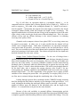
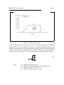
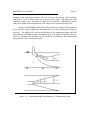
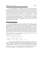
D = Pipe Diameter (m)
θ = Central Angle (rad) = cos-1(1-2yp/D)
yp = Depth of Flow in a Circular Pipe (m)
Eq. (4) will allow an equivalent depth in a rectangular channel, ych, to be
computed based on a pipeline that is flowing partially full at a depth of yp. However, in
order to compute ych, the width of the rectangular channel, B, - which is not known must be supplied. Consequently the program user must supply an assumed value for the
rectangular channel bottom width and compute the depth of flow accordingly. The
approach outlined above will insure that the velocity in the rectangular section is the same
as the velocity in the circular pipe for the same effluent discharge rate. This is key since
effluent velocity and not effluent discharge is the critical parameter in evaluating
receiving water quality effects.
Channels used to transport releases from upland CDF’s to receiving waters may
be natural or man-made. In either case, it is quite possible that the channel will not
exhibit a true rectangular shape. Under these circumstances, an equivalent rectangular
cross-section must be provided. An analysis similar to the one described above can be
used. The cross-sectional area of the actual channel and a rectangular channel are equated
and solved assuming a fixed bottom width. The solution will provide the flow depth such
that both channels have the same velocity.
Seepage From Confined Disposal Facilities. For the case of leakage from a
confined disposal facility, the user must specify the total discharge through all porous
dikes which contribute flow to the receiving waters. However, this may not include each
and every side of the facility. At present, CORMIX is unable to model counter-flowing
discharges, that is, discharges where the effluent direction is opposite the receiving water
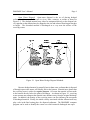
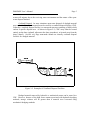
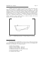
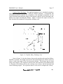
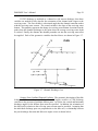
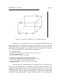
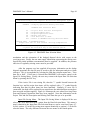
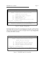
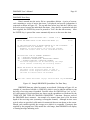
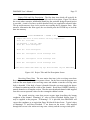
direction. Figure 3-4 shows a three-sided nearshore CDF used to store dredged material.
Of the three sides, side A opposes the current; whereas, sides B and C do not.
Consequently, the discharge supplied to the DROPMIX model must reflect the seepage
through sides B and C. It is the responsibility of the program user to supply accurate
estimates of flow through the porous dike. One possibility is to employ Darcy’s Law or
use flow nets to estimate leakage through the contributing sides of the facility.
Leakage through a porous dike is modeled with the CORMIX2 module assuming
that flow through the dike behaves similarly to flow through a multi-port diffuser. As a
result, information describing the multi-port diffuser must be provided - namely the
number of diffuser ports, the diameter of the individual ports, and the length of the
diffuser. It is assumed that each port has the same diameter.
Because of the wide variability in potential diffuser characterization and the
somewhat unwieldy data requirements associated with diffuser depiction, DROPMIX takes
a simplistic approach when describing diffusers used to simulate dike leakage. First, the