1
COMFILE Technology
www.ComfileTech.com
MSB632RA-DC User’s Manual_
This product is intended for small-scale automation,
standalone applications suitable for a Cubloc controller.
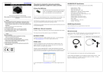
◆ MSB624RA-DC Specifications
The MSB6XX series has a core module equivalent to the Cubloc CB400.
◆ What is the Cubloc?
-
Program Memory : 200KB
The Cubloc is a brand of industrial controllers that can execute BASIC and Ladder Logic
-
BASIC Data Memory : 6KB
simultaneously.
-
Ladder Logic Data Memory : 1KB
PLCs, typically, can only execute Ladder Logic.
-
EEPROM Memory : 4KB (Only Accessible in BASIC)
Due to some limitations of Ladder Logic, it is not able to meet users’ every control
-
DC24V Input s: 20 (Port Numbers 8 ~ 27)
need.
-
High Capacity Relays (10A): 12 (Port Numbers 32 ~ 43)
-
RS232C Communication Port : 2
-
RS485 Communication Port : 1
The Cubloc executes Ladder Logic and Basic concurrently without negatively affecting
-
Analog-To-Digital 10-bit Inputs (0~10V): 4
one another.
-
Analog-To-Digital 10-bit Inputs (0~20mA): 4
-
Power: 24VDC
The Cubloc, with its support of BASIC programming, was created to compensate
for these limitations.
Therefore, users who are familiar with Ladder Logic can use Ladder Logic
to implement most features, and use BASIC to complement the project by filling in the
gaps.
Conversely, those users most familiar with BASIC can use BASIC to implement most
Thank you for your purchase from Comfile Technology
features, and user Ladder Logic to implement any auxiliary functionality.
Insert the following at the very beginning of your source code.
The ability to use two different, yet mutually complementary, programming methods in
#include “MSB6XX”
one controller is one of the Cubloc’s most prominent advantages.
The RS-485 port (channel 3) is already opened with a default baud rate of 57600 by including
Before making use of this product please be sure to read and observe all safety
precautions.
Warning
1. For instruments with risk to life or property (e.g. nuclear power control,
medical equipment, vehicles, railways, aviation, combustion equipment,
◆ MSB Usage Declaration
MSB6XX (i.e. #include "MSB6XX"), so it is not necessary to use OpenCom.
◆ About the MSB Series
the MSB6XX file in Cubloc Studio's installation folder.
The Cubloc core module, in semiconductor form, can be mounted to
a PCB.
Please refer to
To change the baud rate, please use
the set rs232 command.
This is advantageous, as users can integrate the Cubloc
into a custom PCB design in a manner that suits their taste.
◆ Download Cable
recreation equipment, safety devices, etc.), always employ adequate fail-safe
If your PC has a built-in RS-232C (serial port), it can be used to download programs to the
mechanisms.
MSB624RA-DC.
- Risk of fire, personal injury, and/or property damage.
2. Always mount to a panel.
However, to a user without PCB fabrication skills, a custom PCB design can be quite difficult.
3. Do not attempt to repair, inspect, or wire while power is applied.
user must also have the know-how to implement the necessary Input and output circuitry.
If not, a USB-to-serial (RS-232C) adapter can be used.
This
RS-232 3-pin Download Cable
USB-To-Serial + 3-pin Download Cable
4. Do not attempt to alter or repair. Refer to a qualified technician.
5. Confirm all electrical connections
The MSB series was designed to make it easy for users to employ the Cubloc without
having to have professional PCB fabrication technology and skills.
Caution
1. Do not use outdoors.
The MSB series can be installed in the field, have its input and output terminal blocks wired, and can
2. Always use the product within its specifications and ratings.
be used just like existing PLCs.
- Risk of fire and shortening of product’s life.
3. Do not exceed ratings of relay switching contacts.
◆ MSB User’s Manual Composition
4. Does not use in environments with flammable or explosive materials,
moisture, direct sunlight, radiation, vibration and/or shock.
For BASIC or Ladder Logic programming, please refer the Cubloc BASIC User’s Manual.
5. Keep product free of dust and debris.
6. Make connections correctly and confirm polarity by measuring at the
This manual only covers those elements unique to the MSB612RA.
appropriate terminals.
► CE/KCC
Note: The download cable is not included, and must be purchased separately.
◆ CUBLOC STUDIO
To program the MSB series, CUBLOC STUDIO must be used.
It can be downloaded
from www.ComfileTech.com in the “Cubloc” Support section for free.
If using a USB-to-Serial adapater, you must install the necessary drivers to your PC.
the driver is installed, the PC will assign it a COM port number (e.g. COM6).
Studio's PC Interface Setup, select this COM port.
After
In Cubloc
◆ BASIC I/O Map
Direction
Range
Input Port
8 ~ 27
Input Voltage
Description
0V or 24VDC
1 if input is 24V
(20V to 28V is recognized
0 if input is 0V
as a logic high)
Output Port
32 ~ 43
10A Relay Outputs
If 1, Relay is ON
Analog Inputs
Ch 0~7
0~3 (0~20mA)
Use “ADIn(0~7)” to read
4~7 (0~10V)
input
If 0, Relay is OFF
Example) Low 32 'Turn OFF output port number 32 A = In(10) 'Read state of input at port number 10 VA = ADIn(0) 'Read analog input from channel 0
◆ Ladder Logic Memory Map
Designation
Range
Unit
Function
Input Relay P
P0~P31
1 bit
External Input
Output Relay P
P32~P63
1 bit
Relay, etc.. on/off control
Internal Relay M
M0~M511
1 bit
Internal State
Special Purpose Relay F
F0~F127
1 bit
System Status
Timer T
T0~T99
16 bit (1 word)
For Timer
Counter C
C0~C49
16 bit (1 word)
For Counter
Data Region D
D0~99
16 bit (1 word)
Data Storage
By default, all IO is controlled by BASIC at power on.
Ladder Logic must be given
permission to use it using the UsePin command.
Usepin 0, In
‘ From this point on use P0 in Ladder Logic
Usepin 32, Out
‘ From this point on, use P32 in Ladder Logic
Set Ladder On
‘ Place all UsePin commands before enabling Ladder
◆ Status LED
The MSB6xxRA-DC has a status LED that can be used to indicate the product's operating
state.
It can be controlled in BASIC using via pin 64.
High 64
‘ Turn status LED on
Low 64
‘ Turn status LED off
In Ladder Logic, it can be controlled using relay F64.
Set Ladder On ' Enable Ladder Scan
_F(64) = 1
‘ Turn status LED on
_F(64) = 0
‘ Turn status LED off
◆ Parts Description
◆ Digital I/O Specifications
DC 3-Wire Model (NPN type)
◆ Interfacing to Proximity Sensors
Input Specifications
Sensor output connected in reverse
Input Voltage Range
20VDC ~ 28VDC
Recommended Operating Voltage
24VDC
On/Off Switching Speed
10ms (Ladder Scan Time is 10ms)
Input Impedance
2.2kΩ @ 24VDC (Do not connect)
Output Relay Specifications
Proximity sensors can be used to detect the existence, movement, and displacement of
objects without any physical contact with the object.
of automation.
DC 2-Wire Model
They are used quite often in the field
Input Voltage Range
5 ~ 30VDC / 4 ~ 264VAC
Recommended Operating Voltage
6 ~ 27VDC / 6 ~ 240VAC
On/Off frequency
10Hz (10 times per second)
Maximum Current
10A
Minimum Current
100mA per relay
per relay
Sensor output connected in reverse
◆ Analog I/O Specifications
Analog Current Input (0 ~ 3) Specification
Resolution and Error
10-bit, +/- 2%
Input Current Range
0mA ~ 22mA
Recommended Operating Current
4mA ~ 20mA
Type
Non-isolated, Built-in LPF
Analog Voltage Input (4 ~ 7) Specifications
Resolution and Error
Input Voltage Range
DC 3-Wire Model (PNP type)
Sensor output connected in reverse
10-bit, +/- 2%
-0.5VDC ~ 10.5VDC
Don't connect series resistance
Operating Voltage
0VDC ~ 10VDC
Type
Non-isolated, Built-in LPF
◆ Communication Specifications
Communication Port Specifications
Type
RS-232 (+/- 10VDC)
Flow Control
No RTS Flow Control
Maximum Baud Rate
115200
Maximum Distance
2 meters
Modbus Support
Modbus RTU Slave
◆ A Few Simple Examples
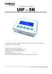
◆ Interfacing with the UIF-5K
3. Input and Output Control
The UIF-5K is a 5-key character LCD panel that can be used in conjunction with the
1. Blinking the Status LED
If Input 8 is active, the status LED and relay 32 are turn switched on.
MSB612RA-DC to add a simple user interface.
The following program will blink the status LED.
#include “MSB6XX”
#include “MSB6XX”
Do
Do
If In(8) = 1 Then
High 64
High 64 'Status LED On
Wait 500
High 32 'Relay 32 On
Low 64
Else
Wait 500
Loop
Low 64
'Status LED off
Low 32
'Relay 32 Off
EndIf
Loop
Blinking the status LED while using Ladder Logic
The following shows how to connect the two together.
The UIF-5k must be powered
separately with a 9V~24V supply.
#include “MSB6XX”
Set Ladder On
Do
_F(64) = 1
Wait 500
_f(64) = 0
Wait 500
The same behavior using Ladder Logic
Loop
You'll find Ladder Logic to be quite easy for handling simple logic.
Blinking the status LED from ladder logic
The following source code will output text to the UIF-5K's display.
2.Toggle Relay
#include “MSB6XX”
Toggle Status LED and relay number 32.
OpenCom 1, 115200, 3, 30, 20
Set UIF 2, 1
Cls
#include “MSB6XX”
Wait 200
Do
Print 27, 80, 1 ' Buzzer On
High 64 'Status LED On
High 32 'Relay 32 On
Wait 500
Low 64
'Status LED Off
Low 32
'Relay 32 off
Wait 500
Loop
CLCDOut 1, 0, “UIF-5K with MSB”
The source code will display a key's scan code when it is pressed.
◆ Interfacing with a CLCD module
◆ Using Modbus
A CLCD module is a character LCD module that can be easily interfaced to any Cubloc-based
The following source code illustrates how to use Modbus
device.
#include “MSB6XX”
OpenCom 1, 115200, 3, 30, 20
Set UIF 2, 1
#include “MSB6XX”
Cls
OpenCom 1, 115200, 3, 50, 50
Wait 200
Set Modbus 1, 1, 20
Print 27, 80, 1 ' Buzzer On
Set Ladder On
CLCDOut 1, 0, “UIF-5K with MSB”
Do
Loop
Dim I as Integer
Dim RX_KEY as Integer
The diagram below shows how to connect to a PC.
Do
Incr I
CLCDOut 1, 2, Dec I
Wait 500
A MSB6XX series device can be connected to a CLCD module via RS-232.
Loop
Be sure the CLCD's
dip switches are on, and the baud rates of both devices are set to 115200.
shows the wiring.
' Key press event handler
5
1
The following
9
6
KEYIN_OCCUR:
RX_KEY = Get(1, 1)
CLCDOut 10, 2, Hex, RX_KEY
Return
1
6
5
9
Modbus communication can be
The following source code illustrates how to display text to a CLCD module.
Each time a key is pressed, a receive interrupt occurs via RS-232 and in turn fires the
KEYIN_OCCUR event handler.
character LCD.
The event handler reads the scan code and displays it on the
#include “MSB6XX”
Set Display 2, 1, 115200, 50
Cls
Wait 200
CLCDOut 1, 0, “CLCD WITH MSB6XX”
tested using CF Term (a free download from www.ComfileTech.com).
◆ Analog Input Example
The following source code illustrates how to use analog inputs.
PC's debug terminal.
For channels 0 ~ 3 (0 ~ 20mA).
#include “MSB6XX”
Dim AD as Integer
Do
AD = ADIn(0)
'Read from channel 0
Debug Dec AD, Cr
Delay 1000
Loop
For channels 4 ~ 7 (0 ~ 10VDC).
#include “MSB6XX”
Dim AD as Integer
Do
AD = ADIn(4)
'Read from channel 4
Debug Dec AD, Cr
Delay 1000
Loop
◆ Dimensions
Results are displayed in the