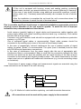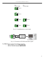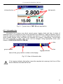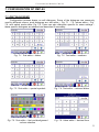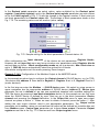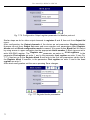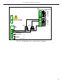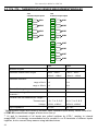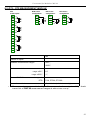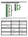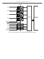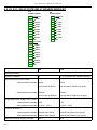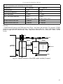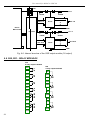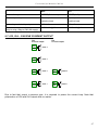
1
USER MANUAL for
MultiCon
device type:
CMC-99 X/X/X-1-X-0XX
firmware version:
1.03 or higher
Read the user's manual carefully before starting to use the unit or software.
Producer reserves the right to implement changes without prior notice.
09.07.2010
V.1.06
User manual for MultiCon CMC-99
CONTENTS
1. BASIC REQUIREMENTS AND USER SAFETY........................................................................................3
1.1. THE USE OF TOUCH-SCREEN........................................................................................................4
2. GENERAL CHARACTERISTICS................................................................................................................4
3. TECHNICAL DATA......................................................................................................................................5
4. DEVICE INSTALLATION............................................................................................................................7
4.1. UNPACKING.......................................................................................................................................8
4.2. ASSEMBLY........................................................................................................................................8
4.3. CONNECTION METHOD.................................................................................................................10
4.4. MAINTENANCE................................................................................................................................16
5. INTRODUCTION TO MULTICON..............................................................................................................16
5.1. UNDERSTANDING MULTICON CMC-99........................................................................................16
5.1.1. Logical channels......................................................................................................................16
5.1.2. Groups.....................................................................................................................................17
5.2. HARDWARE CONFIGURATIONS ..................................................................................................17
6. WORK WITH CMC-99...............................................................................................................................18
6.1. CMC-99 POWER ON.......................................................................................................................18
6.2. THE USE OF TOUCH-SCREEN......................................................................................................18
6.3. DISPLAY...........................................................................................................................................18
6.3.1. Information bar........................................................................................................................19
6.3.2.Navigation bar..........................................................................................................................20
6.3.3. Data panels.............................................................................................................................20
6.3.4. Important messages................................................................................................................22
7. CONFIGURATION OF CMC-99................................................................................................................23
7.1. EDIT DIALOGUES...........................................................................................................................23
7.2. MAIN MENU SELECTION PANEL..................................................................................................26
7.3. FILES MANAGEMENT.....................................................................................................................26
7.4. DEVICE INFORMATIONS, LICENSE AND FIRMWARE UPDATE................................................29
7.5. MAIN MENU ....................................................................................................................................30
7.6. CONFIGURATION MENU STRUCTURE........................................................................................32
7.7. GENERAL SETTINGS.....................................................................................................................36
7.8. INPUT CHANNELS..........................................................................................................................37
7.8.1. Input Channels general settings.............................................................................................38
7.8.2. Input Channels settings for Hardware input and Hardware output monitor modes...............39
7.8.3. Input Channels setting for Modbus mode...............................................................................41
7.8.4. Input Channels settings for Math function and Set point value mode....................................42
7.8.5. Input Channels settings for Controller mode..........................................................................44
7.8.6. Input Channels setting for Profile/timer mode........................................................................45
7.8.7. Examples of Logical Channels configuration..........................................................................46
7.9. BUILT-IN OUTPUTS........................................................................................................................53
7.9.1. Output Mode specific parameters...........................................................................................54
7.9.2.Output Mode specific parameters for Passive current output.................................................55
7.9.3. Examples of build-in output configurations.............................................................................56
7.10. EXTERNAL OUTPUTS..................................................................................................................57
7.10.1.Examples of external output configurations...........................................................................58
7.11. PROFILES/TIMERS.......................................................................................................................58
7.11.1. Examples of Profile/timer configurations..............................................................................59
7.12. CONTROLLERS.............................................................................................................................60
7.12.1. Examples of Controller configurations..................................................................................61
7.13. GROUPS........................................................................................................................................63
7.13.1. Groups configuration.............................................................................................................63
7.13.2. Examples of visualisations of groups...................................................................................64
7.14. MODBUS........................................................................................................................................65
7.14.1. Examples of Modbus protocol configurations.......................................................................70
8. THE MODBUS PROTOCOL HANDLING.................................................................................................73
8.1. LIST OF REGISTERS......................................................................................................................73
2
User manual for MultiCon CMC-99
8.2. TRANSMISSION ERRORS HANDLING..........................................................................................74
8.3. EXAMPLES OF QUERY/ANSWER FRAMES.................................................................................74
9. APPENDIX - INPUT AND OUTPUT MODULES DESCRIPTION.............................................................76
9.1. UI4, UI8, U16, I16 - VOLTAGE AND CURENT MEASUREMENT MODULES...............................76
9.2. TC4, TC8 – THERMOCOUPLE SENSOR MEASUREMENT MODULES......................................80
9.3. RT4 – RTD MEASUREMENT MODULE..........................................................................................81
9.4. D8, D16 – OPTOISOLATED DIGITAL INPUT MODULE................................................................82
9.5. S8, S16 - SOLID STATE RELAY DRIVERS MODULES.................................................................84
9.6. R45, R81 - RELAY MODULES........................................................................................................86
9.7. IO2, IO4 – PASSIVE CURRENT OUTPUT......................................................................................87
Explanation of symbols used in the manual:
!
- This symbol denotes especially important guidelines concerning the installation and
operation of the device. Not complying with the guidelines denoted by this symbol
may cause an accident, damage or equipment destruction.
IF THE DEVICE IS NOT USED ACCORDING TO THE MANUAL THE USER IS
RESPONSIBLE FOR POSSIBLE DAMAGES.
i
- This symbol denotes especially important characteristics of the unit.
Read any information regarding this symbol carefully
1. BASIC REQUIREMENTS AND USER SAFETY
!
- The manufacturer is not responsible for any damages caused by
inappropriate installation, not maintaining the proper technical condition
and using the unit against its destination.
- Installation should be conducted by qualified personnel . During installation all
available safety requirements should be considered. The fitter is responsible for
executing the installation according to this manual, local safety and EMC
regulations.
- The unit must be properly set-up, according to the application. Incorrect
configuration can cause defective operation, which can lead to unit damage or
an accident.
- If in the case of a defect of unit operation there is a risk of a serious threat
to the safety of people or property additional, independent systems and
solutions to prevent such a threat must be used.
- The unit uses dangerous voltage that can cause a lethal accident. The unit
must be switched off and disconnected from the power supply prior to
starting installation of troubleshooting (in the case of malfunction).
- Neighbouring and mating equipment must meet the requirements of appropriate
standards and regulations concerning safety and be equipped with adequate
anti-overvoltage and anti-interference filters.
3
User manual for MultiCon CMC-99
!
!
- Do not attempt to disassemble, repair or modify the unit yourself. The unit
has no user serviceable parts. Units, in which a defect was stated must be
disconnected and submitted for repairs at an authorized service centre.
- In order to minimize fire or electric shock hazard, the unit must be protected
against atmospheric precipitation and excessive humidity.
- Do not use the unit in areas threatened with excessive shocks, vibrations, dust,
humidity, corrosive gasses and oils.
- Do not use the unit in explosion hazard areas.
- Do not use the unit in areas with significant temperature variations, exposed to
condensation or icing.
- Do not use the unit in areas exposed to direct sunlight.
- Make sure that the ambient temperature (e.g. inside the control box) does not
exceed the recommended values. In such cases forced cooling of the unit must
be considered (e.g. by using a ventilator).
!
The unit is designed for operation in an industrial environment and must
not be used in a household environment or similar.
1.1. THE USE OF TOUCH-SCREEN
It is prohibited to use pointers with sharp edges (like knifes, scissors, needles, wires,
nails, bolts etc.) while work with touch-screen. It is strongly recommended to use special stylus
made of plastic or other soft material with smooth ends (for example stylus delivered with the
device). The display of CMC-99 should be also protected against aggressive substances and
extremely high and low temperatures that can cause damages.
2. GENERAL CHARACTERISTICS
MultiCon CMC-99 is a sophisticated multichannel unit which allows simultaneous
measurement, visualisation and control of numerous channels. It is ideal for applications
where some physical quantities represent state of an object and control of this state is based
on concurrent parameters. This device can operate autonomously or with cooperation with
external measurement devices and actuators. Essential features of CMC-99 are listed and
shortly described below.
•
4
Advanced processing unit and system based on LINUX
High computation efficiency of CMC-99 processor allows to run the device under control of
LINUX operating system. Such solution makes firmware flexible and gives the possibility of
simultaneous operation of many processes (like: measurement, communication,
visualisation). Use of LINUX also makes software independent on installed hardware.
User manual for MultiCon CMC-99
•
Colour TFT display with Touch-panel
MultiCon displays all data and dialogues on 3,5” 320x240 pixels, colour TFT screen. Full
control of the device is realised using build in touch-panel what makes operation with CMC99 easy and intuitive.
•
Hardware flexibility and big variety of possible configurations
CMC-99 is designed as modular device consisting of a base and optional input and
output modules. The base contains: main processor, display with touch-screen, Switch
Mode Power Supply (in two versions: 24V and 85-260V) and basic communication
interfaces (USB and RS485). All other modules are optional and can be installed inside the
device according to customer's order. There are three slots designed for installation of
measurement and output modules and one (fourth) slot for advanced communication
module (additional USB Host, 2x RS-485/RS-232 and Ethernet). Basic measurement
modules are: 4/8/16x Voltage/Current input module, 4x RTD input module and 4/8x TC
input module, 8/16x Optoisolated digital input. As output modules can be installed: 8/16x
SSR driver module, 4/8x Relay modules or 2/4x Passive current output module.
•
Freedom of data sources, presentation modes and controlling methods
Multi level structure of CMC-99 firmware allows user for free selection of presented data
sources, presentation modes and controlling methods. CMC-99 displays values of virtual
logical channels which can be fed with measurement data from build in physical channels
or measurement data from remote channels (other devices connected to the CMC-99 by
RS-485 interface), or output states and quantities (looped back results of controlling
processes), generate profiles/timers by user or also mathematical combination of one or
more other logical channels. All of them can be freely named and described by user, and
presented in many forms: as numerical values, vertical and horizontal charts, vertical and
horizontal bars and as needles. Every logical channel (visualised or not) can be used as
an input data of one or more controlling process. CMC-99 implements many different
controlling methods: above and below defined level, inside and outside of defined range
(both with programmable hysteresis and delay of relay on and off ) and PID. Controlling
processes can drive build in physical output or virtual outputs which can be used as input
of logical channels.
3. TECHNICAL DATA
Power supply voltage
(depending on version)
External Fuse (required)
Power consumption
85...230...260V AC/DC; 50 ÷ 60 Hz
or 19...24...50V DC; 16V...24...35V AC
T - type, max. 2 A
typically 15 VA; max. 20 VA
Display
3,5”, TFT colour graphic display, 320 x 240 points,
with LED backlight
Sensor power supply output
24V DC ± 5% / max. 200 mA,
Basic communication interfaces
RS 485, 8N1/2, Modbus RTU, 1200 bit/s ÷ 115200 bit/s
USB Host port, USB Device port
5
User manual for MultiCon CMC-99
Digital input
1 input 0/15..24V DC, galvanic insulation
power consumption: 7,5 mA / 24V,
insulation: 1min @ 500V DC.
Optional communication module*
Second USB Host port
2x Serial RS-485/RS-232
Ethernet 10M RJ-45
Optional input modules*
4/8/16x Voltage (0÷10V) / Current (0÷20mA)**
4x RTD (PT100, PT500, PT1000)**
4/8x TC (J, K, S, T, N, R, B, E)**
8/16x Digital input**
Optional output modules*
4x Relay 5A/250V (cos ϕ = 1)**
8x Relay 1A/250V (cos ϕ = 1)**
8/16x SSR driver (10÷15V, up to 100mA per output)**
2/4x IO Passive current output (4÷20mA)**
Protection level
USB interface on rear panel IP 65 (from front, after using waterproof frame)
IP 42 (from front, with transparent door )
IP 40 (from front, standard)
IP 20 (housing and connection clips)
USB interface from front IP 42 (from front, with transparent door )
IP 40 (from front, standard)
IP 20 (housing and connection clips)
Housing type
Housing material
Housing dimensions
Mounting hole
Assembly depth
Panel thickness
panel
NORYL - GFN2S E1
96 x 96 x 100 mm
90,5 x 90,5 mm
102 mm
max. 5 mm
Operating temperature
Storage temperature
Humidity
Altitude
0°C to +50°C
-10°C to +70°C
5 to 90% no condensation
up to 2000 meters above sea level
Screws tightening max. torque
Max. connection leads diameter
Safety requirements
0,5 Nm
2,5 mm2
according to: PN-EN 61010-1
installation category: II
pollution degree: 2
voltage in relation to ground: 300V AC
insulation resistance: >20MΩ
insulation strength between power supply and
input/output terminal: 1min. @ 2300V (see Fig. 4.1)
EMC
PN-EN 61326-1
* check the current list of measurement modules at www.simex.com.pl
** see the full specification in the appendix
6
User manual for MultiCon CMC-99
4. DEVICE INSTALLATION
The unit has been designed and manufactured in a way assuring a high level of user
safety and resistance to interference occurring in a typical industrial environment. In order to
take full advantage of these characteristics installation of the unit must be conducted correctly
and according to the local regulations.
!
- Read the basic safety requirements on page 3 prior to starting the installation.
- Ensure that the power supply network voltage corresponds to the nominal
voltage stated on the unit’s identification label.
- The load must correspond to the requirements listed in the technical data.
- All installation works must be conducted with a disconnected power supply.
- Protecting the power supply clamps against unauthorized persons must be
taken into consideration.
!
!
This is a class A unit. In housing or a similar area it can cause radio
frequency interference. In such cases the user can be requested to use
appropriate preventive measures.
Carefully check that the insulation used with the unit (Fig. 4.1) meets the
expectations and if necessary use appropriate measures of overvoltage protection.
Additionally, assure the maintenance of appropriate installation air and surface
insulation gaps.
External sensor
supply output
Measurement inputs
RS 485
interface
and
digital input
Internal circuits
Power supply
Outputs circuits
Insulation strength 1min @ 2300V AC
Insulation strength 1min @ 500V AC
No insulation
Fig. 4.1. Schematic diagram showing the insulation between individual circuits of the unit.
7
User manual for MultiCon CMC-99
4.1. UNPACKING
After removing the unit from the protective packaging, check for transportation damage.
Any transportation damage must be immediately reported to the carrier. Also, write down the
unit serial number on the housing and report the damage to the manufacturer.
Attached with the unit please find:
– assembly brackets - 2 pieces,
– warranty,
– user’s manual for CMC-99 unit (device)
4.2. ASSEMBLY
!
- The unit is designed for mounting indoor inside housings (control panel,
switchboard) assuring appropriate protection against electric impulse waves.
Metal housing must be connected to the grounding in a way complying with the
governing regulations.
- Disconnect the power supply prior to starting assembly.
- Check the correctness of the performed connections prior to switching the unit
on.
In order to assembly the unit, a 90,5 x 90,5 mm mounting hole (Fig. 4.2) must be
prepared. The thickness of the material of which the panel is made must not exceed
5mm. When preparing the mounting hole take the grooves for catches located on
both sides of the housing into consideration (Fig. 4.2). Place the unit in the
mounting hole inserting it from the front side of the panel, and then fix it using the
brackets (Fig. 4.3). The minimum distances between assembly holes’ axes - due to
the thermal and mechanical conditions of operation - are 115 mm x 115 mm (Fig.
4.5).
90,5 mm
13 mm
90,5 mm
8 mm
8 mm
13 mm
1 mm
1 mm
Fig. 4.2. Mounting hole dimensions
8
max. 5 mm
User manual for MultiCon CMC-99
98 mm
8 mm
removable terminals
Fig. 4.3. Installing of brackets
GOOD
back side
of device
connector
WRONG
back side
of device
connector
Fig. 4.4. Connectors removing method
9
User manual for MultiCon CMC-99
115 mm
115 mm
Fig. 4.5. Minimum distances when assembly of a number of units
4.3. CONNECTION METHOD
Caution
!
- Installation should be conducted by qualified personnel. During installation all
available safety requirements should be considered. The fitter is responsible for
executing the installation according to this manual, local safety and EMC
regulations.
- The unit is not equipped with an internal fuse or power supply circuit breaker.
Because of this an external time-delay cut-out fuse with minimal possible nominal
current value must be used (recommended bipolar, max. 2A) and a power supply
circuit-breaker located near the unit. In the case of using a monopolar fuse it must
be mounted on the phase cable (L).
- The power supply network cable diameter must be selected in such a way that in
the case of a short circuit of the cable from the side of the unit the cable shall be
protected against destruction with an electrical installation fuse.
- Wiring must meet appropriate standards and local regulations and laws.
- In order to secure against accidental short circuit the connection cables must be
terminated with appropriate insulated cable tips.
- Tighten the clamping screws. The recommended tightening torque is 0.5 Nm.
Loose screws can cause fire or defective operation. Over tightening can lead to
damaging the connections inside the units and breaking the thread.
- In the case of the unit being fitted with separable clamps they should be inserted
into appropriate connectors in the unit, even if they are not used for any
connections.
- Unused clamps (marked as n.c.) must not be used for connecting any
connecting cables (e.g. as bridges), because this can cause damage to the
equipment or electric shock.
10
User manual for MultiCon CMC-99
!
- If the unit is equipped with housing, covers and sealing packing, protecting
against water intrusion, pay special attention to their correct tightening or clamping.
In the case of any doubt consider using additional preventive measures (covers,
roofing, seals, etc.). Carelessly executed assembly can increase the risk of electric
shock.
- After the installation is completed do not touch the unit’s connections when it is
switched on, because it carries the risk of electrical shock.
Due to possible significant interference in industrial installations appropriate measures
assuring correct operation of the unit must be applied. To avoid the unit of improper
indications keep recommendations listed below.
-
Avoid common (parallel) leading of signal cables and transmission cables together with
power supply cables and cables controlling induction loads (e.g. contactors). Such cables
should cross at a right angle.
Contactor coils and induction loads should be equipped with anti-interference protection
systems, e.g. RC-type.
Use of screened signal cables is recommended. Signal cable screens should be
connected to the earthing only at one of the ends of the screened cable.
In the case of magnetically induced interference the use of twisted couples of signal
cables (so-called “spirals”) is recommended. The spiral (best if shielded) must be used
with RS-485 serial transmission connections.
In the case of interference from the power supply side the use of appropriate antiinterference filters is recommended. Bear in mind that the connection between the filter
and the unit should be as short as possible and the metal housing of the filter must be
connected to the earthing with largest possible surface. The cables connected to the filter
output must not run in parallel with cables with interference (e.g. circuits controlling relays
or contactors).
max. 1.5 mm
Connections of power supply voltage and measurement signals are executed using the
screw connections on the back of the unit’s housing.
!
5-6 mm
Fig. 4.6. Method of cable insulation replacing and cable terminals dimensions
All connections must be made while power supply is disconnected !
11
User manual for MultiCon CMC-99
Slot C
Slot B
Slot A
1
2
Power supply
(depending on version)
USB
device
3
4
5
6
7
8
GND
GND-I
BA+
+24V DC ±5%
Imax. = 200mA
digital input
0/15..24V DC
USB
host
RS-485
insulated
Fig. 4.7. Terminals description
i
Only most left terminals (Power supply, USB Device port, Sensor supply output,
Digital input and RS-485) are standard. Advanced communication module
(additional serial, USB and Ethernet interfaces), and three input/output modules
(slot A, slot B, slot C) showed in Fig. 4.7 depends on customer's order. According to
the order these terminals can look differently or be not present. Terminals and
connections of available modules are shown on Fig. 4.9-4.12.
N 1
L 2
!
FUSE
N
L
Depending on version:
85...230...260V AC/DC or
19...24...50V DC; 16...24...35V AC
Fig. 4.8. Connection of power supply
12
User manual for MultiCon CMC-99
GND
4 x 0-10V
AIN9
AIN10
AIN11
AIN5
AIN6
AIN7
AIN8
GND
AIN12
GND
AIN13
AIN5
AIN6
AIN7
AIN8
GND
n11
n12
n13
n14
n15
4 x 0-10V
n16
n17
n18
n19
n20
AIN14
AIN15
AIN16
GND
n06
n07
n08
n09
n10
GND
AIN9
n11
n12
n13
n14
n15
AIN10
AIN11
AIN12
GND
AIN13
n16
n17
n18
n19
n20
AIN14
AIN15
AIN16
GND
4 x 0-10V
AIN4
AIN1
AIN2
AIN3
AIN4
GND
AIN5
4 x 0-10V
n06
n07
n08
n09
n10
GND
n06
n07
n08
n09
n10
AIN3
n01
n02
n03
n04
n05
AIN6
AIN7
AIN8
GND
AIN9
4 x 0-10V
AIN8
AIN4
AIN2
16 voltage inputs
AIN10
AIN11
AIN12
GND
AIN13
4 x 0-10V
AIN7
AIN3
AIN1
4 x 0-20mA
AIN6
AIN2
n01
n02
n03
n04
n05
4 x 0-20mA
AIN5
4 x 0-20mA
GND
AIN1
4 x 0-20mA
n01
n02
n03
n04
n05
4 x 0-10V
AIN4
4 current + 4 voltage inputs
AIN14
AIN15
AIN16
GND
Fig. 4.9. Available current and voltage input modules
TC4
4 thermocouple inputs
RT4
4 RTD inputs
n01
n02
n03
n04
n05
n06
n07
n08
n09
n10
n11
n12
n13
n14
n15
n16
AIN1
n16
n17
n18
n19
n20
AIN3
UI4
AIN2
n11
n12
n13
n14
n15
AIN2
AIN3
n06
n07
n08
n09
n10
AIN1
AIN4
n01
n02
n03
n04
n05
U16
4 x 0-20mA
16 current inputs
4 x 0-20mA
I16
8 current + 8 voltage inputs
4 x 0-20mA
UI8
TC8
8 thermocouple inputs
n01 n02 +
AIN1
n01 n02 +
AIN1
n03
n04 +
AIN2
n03
n04 +
AIN2
-
-
n05 n06 +
AIN3
n05 n06 +
AIN3
n07
n08 +
AIN4
n07
n08 +
AIN4
n09 n10 +
AIN5
n11
n12 +
AIN6
-
-
-
n13 n14 +
AIN7
n15
n16 +
AIN8
-
Fig. 4.10. Available RTD and TC input modules
13
User manual for MultiCon CMC-99
D16
16 Digital inputs
D8
8 Digital inputs
n01
n02
n03
n04
n05
n06
n07
n08
n09
n10
n11
n12
n13
n14
n15
n16
n17
n18
n19
n20
n01
n02
n03
n04
n05
n06
n07
n08
n09
n10
DIN1
DIN2
DIN17
DIN3
DIN4
COM 1-4
DIN5
DIN6
DIN18
DIN7
DIN8
COM 5-8
DIN21
DIN1
DIN2
DIN9
DIN3
DIN4
COM 1-4
DIN11
DIN5
DIN6
DIN10
DIN7
DIN8
COM 5-8
DIN9
DIN10
DIN19
DIN11
DIN12
COM 9-12
DIN13
DIN14
DIN20
DIN15
DIN16
COM 13-16
Fig. 4.11. Available Digital input modules
S16
16 SSR outputs
R81
8 relay outputs 1A/250V
n09
n10
n11
n13
n14
R1
n04
n05
n06
n08
n09
n10
R8 R7
n12
n03
n07
R6 R5
n08
R4
n07
n02
R2
n06
R3
n05
n01
R3
n04
R2
n03
R45
4 relay outputs 5A/250V
n11
n12
R4
n02
R1
n01
n01
n02
n03
n04
n05
n06
n07
n08
n09
n10
n11
n12
n13
n14
n15
n16
n17
n18
n19
n20
+10..24V DC
SSR1
SSR2
SSR3
SSR4
SSR5
SSR6
SSR7
SSR8
GND
+10..24V DC
SSR9
SSR10
SSR11
SSR12
SSR13
SSR14
SSR15
SSR16
GND
Fig. 4.12. Available output modules
14
S8
8 SSR outputs
n01
n02
n03
n04
n05
n06
n07
n08
n09
n10
+10..24V DC
SSR1
SSR2
SSR3
SSR4
SSR5
SSR6
SSR7
SSR8
GND
User manual for MultiCon CMC-99
n07
n08
AOUT 3
AOUT 2
n05
n06
PASSIVE
n05
n06
AOUT 4
AOUT 2
AOUT 1
n07
n08
PASSIVE
n03
n04
PASSIVE
n01
n02
PASSIVE
2 current output
PASSIVE
IO2
4 current output
PASSIVE
IO4
AOUT 1
RS-485
Fig. 4.13. Available passive current output
6
7
8
GND
BA+
RS232/RS485
or USB/RS485
interface
Fig. 4.14. Connection of RS-485 transmission signals
The CMC-99 device supports the following converters:
– USB / RS-485 converter (SRS-USB/4-Z45)
– RS-232 / RS-485 converter (SRS-2/4-Z45)
15
User manual for MultiCon CMC-99
4.4. MAINTENANCE
The unit does not have any internal replaceable or adjustable components available to
the user. Pay attention to the ambient temperature in the room where the unit is operating.
Excessively high temperatures cause faster ageing of the internal components and shorten the
fault-free time of unit operation.
In cases where the unit gets dirty do not clean with solvents. For cleaning use warm water with
small amount of detergent or in the case of more significant contamination ethyl or isopropyl
alcohol.
!
Using any other agents can cause permanent damage to the housing.
Product marked with this symbol should not be placed in municipal waste. Please
check local regulations for disposal and electronic products.
5. INTRODUCTION TO MULTICON
5.1. UNDERSTANDING MULTICON CMC-99
The MultiCon CMC-99 were developed as universal multichannel controller. To maintain
this concept also its firmware was written with multi level structure. The device runs under
control of LINUX operating system keeping all subsystems ready to use and allowing
independent and simultaneous operation of many processes (communication, data acquisition,
post-processing, visualisation etc.). Such approach gives great advantages of highest level
application, making it flexible and dynamically configurable. Similarly data structures and
streams was implemented in a quite different way than in most of similar devices. The main
difference is the concept of Logical Channels as a bridge: physical inputs and outputs visualisation and controlling processes. Designers of MultiCon decided to use such solution to
increase functionality of the device and make software near fully independent on the hardware.
5.1.1. Logical channels
Logical Channel is a data stream existing in memory of the device, having it's name and
could be displayed, used as input data for controlling process (or processes), controlling of
physical output or as input data of other Logical Channels. The CMC-99 can contain as much
as 60 Logical Channels, every of these channels can be configured to represent:
measurement data from build in physical input channels, states and output data of physical
output channels, states and data coming from outputs of controlling processes, states of virtual
input channels and timers, or mathematical combination of other Logical Channels. To make
visualization more clear Logical Channels can be gather into a Groups.
16
User manual for MultiCon CMC-99
5.1.2. Groups
The Group is a set of 1-6 Logical Channels. CMC-99 can visualize on the same screen
only channels belonging to the same Group, additionally Groups has their individual names
what makes operation with device very clear. Every Logical Channel can belong to one or
more groups simultaneously, and also not to belong to any group (then may not be visualized,
but still can be used for other processes). It is common that channels belonging to the same
Group are related one to another in some way (for example representing parameters of single
object or representing similar parameters of few separate objects) but it is also possible to
create a Group consist of completely unrelated channels.
The use of Groups, Logical Channels and mathematical combinations of them gives
incredible flexibility of the software, allowing easy designing or advanced controlling methods
and its visualisation with low cost MultiCon CMC-99.
Example:
We can measure only voltage and current of some heater, but we would like to observe
and control average power emitted by this heater. First at all we define 3 Logical Channels first fed with data from voltage input, second fed with data from current input, and third fed by
result of multiplication of Logical Channels 1 and 2 then gather them into a single Group
named HEATER. In this way we can display 3 graphs on the screen: voltage, current and
power of the heater. Moreover the third channel can then be used as input for regulation of
power emitted by the heater and control build in physical relay. Additionally state of the relay
can fed fourth Logical Channel. To display state of the relay, it is necessary to add it to the
same Group together with previous three channels.
5.2. HARDWARE CONFIGURATIONS
The functionality of CMC-99 can be fit to the user's needs. The base of CMC-99
contains: main processor, display with touch-screen, Switch Mode Power Supply (in one of two
versions: 24V and 85-260V) and basic communication interfaces like USB and RS485. See
Fig. 4.7 - most left connectors. All other modules are optional and can be installed inside the
device according to customer's order. Next to basic connectors is a place of advanced
communication module. In the simplest version this module can be equipped only with rear
USB Host connector (this is standard fitments for IP-65 version of the CMC-99). Full version of
this module contains also 2 additional serial ports (RS485 and RS485 split with RS232) and
10Mb Ethernet RJ-45 connector.
Three slots designed for build in hardware inputs and outputs are installed on the right
side of the case (see Fig. 4.7, terminals marked: slot A, slot B and slot C). The actual view of
these terminals varies depend on module type. Shortened descriptions of available modules'
terminals are shown on Fig. 4.9-4.12. Measurement and actuators modules are constantly
developed, so current list of available modules varies (visit www.simex.com.pl to check current
list of CMC-99 modules). Basic measurement modules are: 4/8/16x Voltage/Current input
module, 4x RTD input module and 4/8x TC input module. Output modules are: 8/16x SSR
driver module or 8x Relay 1A/250V, 4x Relay 5A/250V modules and 2/4x IO passive current
output.
17
User manual for MultiCon CMC-99
6. WORK WITH CMC-99
6.1. CMC-99 POWER ON
After power on a starting Logo is showed on CMC-99 display. While operation system is
being loaded a progress bar is visible in the middle of the screen. After that main application is
stared. During this process screen may stay dimmed by 3-5 seconds. Please wait until end of
this operation before starting to operate with the device.
6.2. THE USE OF TOUCH-SCREEN
It is prohibited to use pointers with sharp edges (like knifes, scissors, needles, wires,
nails, bolts etc.) while work with touch-screen. It is strongly recommended to use special stylus
made of plastic or other soft material with smooth ends (for example stylus delivered with the
device). The display of CMC-99 should be also protected against aggressive substances and
extremely high and low temperatures that can cause damages.
i
For cleaning a special liquid designed for LCD screens and soft cloth should be
used.
6.3. DISPLAY
MultiCon displays all data and dialogues on 3,5” 320x240 pixels, colour TFT screen.
New devices has display protected with transparent thin foil. This protective layer should be
removed before use to ensure perfect visibility of pictures and sensitivity of touch-screen which
is used to operate with the device.
While normal operation CMC-99 displays data in a form selected by user, but at any time
it is possible to switch presentation mode or enable configuration dialogue boxes. All details of
the user interface are fit up to make use of device easy and intuitive. To change displaying
mode or enter menu touch the screen of CMC-99 with stylus. Further information about menu
and presentation modes are described in further chapters.
i
18
Detailed description of all elements visible on the screen are contained in further
chapters.
User manual for MultiCon CMC-99
information bar
data panels
Fig. 6.1. Typical view of CMC-99 main application
6.3.1. Information bar
Information bar informs user about current group, logging, date and time. In place of
standard name it is possible to enter more descriptive for clearance. Logging indicator used to
show the operations related to logging. Indicator may shine in 3 colours: grey, blue and yellow
which means disable, active and save the samples into memory, respectively. Current date
and time presented in upper right corner can be changed using appropriate menu (see
chapter: CONFIGURATION OF CMC-99).
date
time
group number
logging indicator
name of the group which is visible on the display
Fig. 6.2. View of information bar
!
If the logging indicator light yellow (save the samples into memory) don't turn off the
device because the date will be lost
19
User manual for MultiCon CMC-99
6.3.2.Navigation bar
The touch of the screen at any place causes displaying of navigation bar.
Fig. 6.3. Main window of device – running navigation bar
This bar contains three kinds of buttons:
switching between visualisation modes of current group
entering the main menu (see details in paragraph:
CONFIGURATION OF CMC-99)
switching between presented group of channels
i
To enter directly into configuration menu of particular channel, press and hold
screen over the channel data panel for 3-4 seconds. Similarly to go directly to
configuration of displayed group, touch and hold for few seconds upper information
bar. In both cases if password is set then user has to enter the password before
entering the configuration.
6.3.3. Data panels
The great deal of screen is being used for channels visualisation. Data can be presented
in one of few modes (as numerical values, as charts, as bars and as needles). All channels of
current group are simultaneously presented in the same mode. In the current version of
software there is no possibility to mix different modes in one view. Figures 6.4 – 6.8 show
examples of different views. The switching between visualisation modes can be done invoking
bottom navigation bar and pressing buttons [MODE↑] or [MODE↓], (see paragraph:
Navigation bar)
On every data panel there are available following informations: channel data value, data unit,
channel's name and number of Logical Channel, on some modes there is also visible
percentage indicator of value in the relation to it's full scale.
Every Group of Logical Channels can be presented in one of 6 modes:
as numerical values Fig. 6.4
•
as horizontal bars Fig. 6.5
•
as vertical bars Fig. 6.5
•
as horizontal charts Fig. 6.6
•
20
User manual for MultiCon CMC-99
•
•
as vertical charts Fig. 6.6
as needles Fig. 6.7
There is also possibility to show many groups on single screen (Fig. 6.9 ). In this mode
particular channels belonging to the same group are displayed one under another, and
particular groups are placed side by side. As much as 5 groups can be displayed
simultaneously on single screen.
Fig. 6.4. Examples of Numerical Values presentation mode
Fig. 6.5. Examples of Horizontal and Vertical Bars
Fig. 6.6. Examples of Horizontal and Vertical Charts
21
User manual for MultiCon CMC-99
Fig. 6.7. Examples of Needles
Fig. 6.8. Examples of simultaneous presentation of Many Groups
6.3.4. Important messages
22
Fig. 6.9. Information message
Fig. 6.10. Question message
Fig. 6.11. Warning message
Fig. 6.12. Alert message
User manual for MultiCon CMC-99
7. CONFIGURATION OF CMC-99
7.1. EDIT DIALOGUES
Configuration process bases on edit dialogues. Some of the dialogues are commonly
used by different menus, such dialogues are: text editor – Fig. 7.1 - 7.5, values editor – Fig.
7.6, and switch mode editor Fig. 7.9. There are also dialogues specific for some settings these specific dialogues are showed and described if necessary.
Fig. 7.1. Text editor – letters
Fig. 7.2. Text editor – numbers
Fig. 7.3. Text editor – special symbols
Fig. 7.4. Text editor – national letters
Fig. 7.5. Text editor – font and background
colours selection
Fig. 7.6. Value editor – decimal form
23
User manual for MultiCon CMC-99
24
Fig. 7.7. Value editor – hex form
Fig. 7.8. Value editor – binary form
Fig. 7.9. Single switch type editor
Fig. 7.10. Multiple switch type editor
Fig. 7.11. File editor
Fig. 7.12. File editor
User manual for MultiCon CMC-99
Functions of common buttons
“Exit” - exits from current menu or sub-menu
”OK” - allows to accept choice or changes of edit dialogue (and exit
from this dialogue)
“Cancel” - allow to reject entered choice or changes of edit dialogue
(and exit from this dialogue)
Selection of element for edition. Arrow buttons allow to select
successive elements (groups, logical channels, controllers or outputs).
Middle button allows direct selection of particular element from the list.
Navigation keys in switch type dialogues.
Move arrows. Allow to move cursor on the edited text.
“Caps lock” - switches between lower and upper case letters.
“Backspace”. While value editing pressing this button deletes last
visible number. While text editing last edited symbol or symbol
showed directly before cursor.
“Clear” - clears whole number while editing of the values.
“Sign” - changes sign of edited value.
This button allow to delete selected file.
“All” - selects all the available options.
“None” - disable all the available options.
Pressing this button allow to use Text editor window.
25
User manual for MultiCon CMC-99
7.2. MAIN MENU SELECTION PANEL
Pressing [MENU] button of Navigation bar enters main selection panel (Fig. 7.13). This
panel allows to select between entering the Device Configuration, Files management and
Device Information screen.
Fig. 7.13. Main menu window
Safe shutdown button allow to safe power off the device. After pressing the button and
accepting the warning message the screen will be look like in the Fig. 7.14.
Fig. 7.14. The screen after pressing the Safe shutdown button
7.3. FILES MANAGEMENT
This menu is for managing files i.e. to transmit and receive data to the flash memory. The
main menu is shown in the Fig. 7.15. There are 2 parameters: Recordings and
Configuration. Recording parameter allow to management recordings files. Available only in
the case of buying a licence key. In the absence of this license in the Files management
menu, there is only once parameter – the Configuration files.
Menu parameter Recordings is shown in the Fig. 7.16.
26
User manual for MultiCon CMC-99
Fig. 7.15. Files management menu
In order to export selected logging files we select appropriate group of selected files logging
(see Fig. 7.18) and then connected to a device with flash memory we press the Export
selected files button. The symbol ”----” means that no logging files in the group was not
selected. Descriptions of files are defined in the menu Groups (see Chapter 7.13 Groups).
Similarly, to export logging files does delete files. In order to delete files after selected files in
appropriate groups we click Delete selected files button.
Fig. 7.16. View of the “Logging files” menu
Second parameter in the Management files is Configuration. After enter in the submenu user
can Load/Save the configurations and templates. CMC-99 Allow load/save configurations
defined by user, i.e. general settings, logical channels, build-in output, modbus settings,
profiles/timers, controllers and group. Sample view window when configuration is changes
shown in the Fig. 7.17. Save/load templates modbus allow to save/load configuration settings
for the Modbus protocol, i.e. name, channel configuration of the device (the list of inputs and
outputs) and the register blocks (Block list). - see Chapter 7.14 Modbus. Having saved these
templates modbus we can at any time to quickly communication between CMC-99 and SLAVE
device only select appropriate address of SLAVE device.
27
User manual for MultiCon CMC-99
The process of exchanging flies: configurations or templates modbus between the device and
flash memory starts after when you connect flash memory to CMC-99. Then enter Files
management → Configuration files menu. If we want to Load files than in the window panel
will appear image of flash memory with available configurations or modbus templates files for
configurations or with extension .cfg or .mcfg respectively. Please note that name of files is
set by user. If we want to save files after pressing button Save configuration or Modbus
templates appears window panel with available files that can be appropriately called by
pressing the button with the symbol keys in the upper left corner. Next we confirm the save
and after few moments the date is stored in flash memory. Sample configuration files are
placed in Fig. 7.18.
Fig. 7.17. View window when the configuration changes
Fig. 7.18. Example of logging and configuration files
28
User manual for MultiCon CMC-99
7.4. DEVICE INFORMATIONS, LICENSE AND FIRMWARE UPDATE
This screen gives basic informations about software and hardware of the device.
Informations about
hardware
(slots fitments)
Information
about firmware
Fig. 7.19. Device Information screen
Firmware update button gives possibility for easy maintaining of up to date firmware version.
Before updating user has to download the newest version of software from www.simex.com.pl
and store it on Flash Disk. Next insert Flash Disk into USB host port of CMC-99 and run
update process pressing Firmware update button. During updating it is prohibited to switch off
the power or remove Flash Disk from USB port. Broken or careless updating can cause device
damage.
Fig. 7.20. Device information menu
To prevent accidental running of update process additional confirmation warning is displayed.
Fig. 7.21. Confirmation dialogue
Enter licence key button allow to enter license key depending on the user receives additional
software options to increase functionality of the device.
29
User manual for MultiCon CMC-99
Service options button is protected password and unavailable for user.
7.5. MAIN MENU
To avoid settings against accidental or unauthorized change user has to enter the
Password before entering configuration menu. If user set protection, then before entering
deeper settings dialogues an ask for password is displayed.
*****
Fig. 7.22. Enter password dialogue
This button invokes software keyboard window allowing enter the password. While
password entering, letters are replaced with star signs.
If incorrect password is entered then appropriate warning is displayed Fig. 7.23 and
configuration is impossible.
Fig. 7.23. Warning message after wrong password entering
If entered password is correct then main menu selection panel appears (Fig. 7.24).
Fig. 7.24. Main menu selection panel
To exit from this menu (with configuration changed or not) press Exit button located in upper
right corner of the screen. Due to configuration process operates on-line it is necessary to
30
User manual for MultiCon CMC-99
confirm entered changes. Choice panel is displayed, and user can Save changes or Revert
configuration to previous state.
Fig. 7.25. Save / revert changes window
31
User manual for MultiCon CMC-99
7.6. CONFIGURATION MENU STRUCTURE
Basic
General settings
Input channels
Language
see next page
Date and time
LCD screen
Backlight
Screen saver
Initial view
Display mode
Displayed group
Automatic view change
Display mode
Displayed group
Change mode
Display time
Setup list
Add a new view
Display time
Delete this view
Change timeout
Move to pos.
Name
Name
Built-in output
Mode = Binary output
Mode
Mode
Source
Source
Alarm state
Alarm state
Lavels
Levels
Level
Level
Lower level
Lower level
Upper level
Hysteresis
Upper level
Hysteresis
Timing
ON delay
Timing
ON delay
OFF delay
Min. ON time
OFF delay
Min. ON time
Min. OFF time
Min. OFF time
Mode = analog output
Source
Input levels
Lower level
External output
Upper level
Output levels
Lower level
Upper level
Alarm level
32
User manual for MultiCon CMC-99
General setting
Input channel
Group
Source= analog input
Name
Mode
Mode = Hardware input
Source
Low limit
Configure source
High limit
Profiles/timers
Controllers
Name
Unit
Mode
Built-in output
External output
Name
Source = digital input
Mode = Hard.out.monitor
Filter time
Source
Modbus
Access options
Source = Demo
Mode = Modbus
Mode
Port
SLAVE device
Unit
Device input
Low limit
High limit
Mode = Set point value
Unit
Function
Source X
Type of source Y
Source Y
X error handling
Set point value
Mode = Math function
Function
Mode = Controller
Controller num.
Output unit
Point 1
Input value
Input value
Output value
Configure source
Processing
Period
High state time
Rise time
Point 2
Feedback channel
Source
Min. simulated val.
Max.wart.symulacji
Output value
Set point channel
Mode = Profile/timer
Profiles/timers menu
Input unit
Scaling = linear
Scaling = offset
Value to add
Scaling = user char.
Output unit
Input value
Output value
Scaling
Number of points
Add point
Configure scaling
Edit points
Delete point
Filter type
Filter conf.
Decay constant
Displaying
Format
Precision
Off-state text
On-state text
Graph low
Graph high
33
User manual for MultiCon CMC-99
Name
Profiles/timers
Months
Tiggering mode
Triggerin source
Triggering times
Days
Week days
Duration
Idle value
Hours
Shape
Section list
Minutes
Final value
Looping
Seconds
Return to possition
Controller name
Controllers
Mode
Group
Dead zone
Display option
Controller parameters
Name
P coefficient
Charts
I coefficient
Barsi
D coefficient
Line width
Differentiated signal
Time scale
Controller output
Background
Output unit
Channels
Offset
Pozycja
Slot 1 1
Low output limit
Pozycja
Slot 2 2
High output limit
Slot 3
Slot 4
Slot 5
Groups
Slot 6
Logging option
Mode
Triggering source
Description
Base period
Mode
Base unit
Baud rate
Alternative mode
Request timeout
Modbus
Access options
34
SLAVE device
Access password
See next page
Request retials
Alt. trig. sourse
Alternative period
Alternative unit
Logging options
User manual for MultiCon CMC-99
General setting
Input channel
Built-in output
External output
Mode
Profiles/timers
Baud rate
Controllers
Request timeout
Group
Request retials
Device type
Modbus
SLAVE device
Load device templ.
Address
Device name
Access options
Reg.num.displaying
Device templates
Load device templ.
Channel value
Value register
Register number
Device channels
Decimal point
Input list
Dec. poin register
Output list
Channel status '-HI-'
Register type
Save device templ.
Control type
Block config. mode
-HI- register
Max. Block size
-HI- value
Block list
Channel status '-LO-'
-LO- state
32-bit reading
-LO- register
-LO- value
Date shift
Channel status '-WAIT-'
Data mask
-WAIT- state
Output register
Register number
Data format
Block type
Register size
Ordering
Channel value
Register blocks
-HI- state
Data format
Output active
First register
Last register
32-bit reading
Ordering
Date mask
Data shift
-WAIT- register
-WAIT- value
Channel status '-ERR-'
-ERR- state
-ERR- register
-ERR- value
35
User manual for MultiCon CMC-99
7.7. GENERAL SETTINGS
General settings are used to configure main parameters of the user interface,
appearance of the device after power up and automatic data presentation events. Figure 7.26
shows settings of user interface: language, date and time, backlight, and screen saver.
Fig. 7.26. General Settings – interface settings
Figure 7.27 shows settings of initial view: Group and it's visualisation mode. If user needn't
automatic changes of displayed group or mode then can leave Automatic view change
disabled. If any auto operations are required then user can select one of few changing
methods, also additional fields on the General Settings appear.
Fig. 7.27. General Settings – Initial view settings.
Figure 7.28 shows view of the General Settings after enabling automatic changes of
visualisation modes or groups. Additional fields allow to select period of particular mode/group
visibility - Display time and Change timeout (time to the first auto action after last manual
change of the mode or group).
36
User manual for MultiCon CMC-99
Fig. 7.28. General Settings – automatic changes of modes or groups
If Change mode is set to detailed list mode then in place of Display time parameter an
Setup list button is displayed (Fig. 7.29 left). After pressing this button additional submenu
window appears, allowing defining of successive views (Fig. 7.29 right).
PRESS
Fig. 7.29. General Settings – automatic changes of modes and groups
To create additional views use Add a new view button, to delete current view press Delete
this view. Selection of currently edited view can be done by pressing arrows on upper bar.
Pressing number allows to jump directly to definition of required view (appropriate number of
views must be firstly defined).
7.8. INPUT CHANNELS
This sub-menu is used for configuration of Logical Channels. It is named Input
Channels to suggest user that data (values) of defined here channels can be treated as input
data for outputs, controllers or other Logical Channels and can be collected into a Groups for
simultaneous visualisation. To see detailed definition of Logical Channel see Introduction to
MultiCon
i
To jump directly into configuration mode of particular Logical Channel touch and
hold for few seconds data panel of this channel on display while data visualisation.
If password is set then user has to enter the password before entering the
configuration.
37
User manual for MultiCon CMC-99
7.8.1. Input Channels general settings
There is available as much as 60 Logical Channels. Every channel has its individual name.
To change it, simply press button next to label Name. In hardware input mode Unit is related
to the source channels, and for Demo can be changed after pressing Configure source
button. For Set point value mode and Controller mode unit is free definable directly from
main window of Logical Channel configuration. If Scaling is enabled then unit can be
redefined by Output unit parameter in scaling configuration menu (see Fig. 7.36).
Fig. 7.30. Input channels menu – Logical Channel general settings
Parameter Mode defines the kind of data source of the Logical Channel. User can select one
of 8 modes – ( disabled, Hardware input, Hardware output monitor, Modbus, Set point value,
Math function, Controller and Profile/timer). If Logical Channel is disabled then there are no
other parameters to set. Every other mode enables different set of parameters for
configuration. All of them enables parameters for configuration of Displaying Fig. 7.31
Fig. 7.31. Input channels menu – two views of parameters for Displaying configuration
Numeric format of the data can be expressed with desired precision. However user should
remember that measurement resolution and precision of external sensors are finite, and
usually not better than 0.1%.
Binary format of data allow to select strings (texts) for it's on and off state. This strings can
describe the state of sensor or output. It is possible to input any string with desired background
and foreground colour. Also empty string (spaces) is possible, in this case the text can pretend
kind of LED indicator.
38
User manual for MultiCon CMC-99
Both data formats (numeric and binary) allow to define lower and upper limits of the graph.
This parameters gives possibility to set scale of the graph values making it readable. Time
scale of the graph is common for whole Group and can be set using Groups menu.
7.8.2. Input Channels settings for Hardware input and Hardware output monitor modes
When Logical Channel is switched to mode Hardware input then parameters related to
hardware are displayed Fig. 7.32.
Fig. 7.32. Input channels menu – parameters specific for Hardware Input mode
Parameter source allows to select physical input channel, and button Configure Source
enters additional panel specific for selected input source. Shortened description of
configuration of the physical inputs are shown on Fig. 4.9-4.12 devoted to particular
measurement modules.
Selection of Hardware output monitor mode causes displaying configuration menu as
presented in Fig. 7.33.
Fig. 7.33. Input channels menu – parameters specific for Hardware Output Monitor mode
39
User manual for MultiCon CMC-99
In both these modes there are also visible configuration parameters for Processing (Fig.
7.34). Processing allows to recalculate incoming data (add offset or transform them according
to linear or user defined characteristic). Panels for configuration of different types of scaling
are presented in figures 7.35 – 7.37.
Fig. 7.34. Input channels menu – parameters for Processing configuration
Fig. 7.35. Configuration of Offset type scaling
Fig. 7.36. Configuration of Linear scaling
40
User manual for MultiCon CMC-99
PRESS
Fig. 7.37. Configuration of User characteristic scaling
When User characteristic is selected then edition of up to 20 points is possible. Pressing
Edit points button (fig. Fig. 7.37) invokes point configuration window.
Filter allows to smooth incoming data. Figure 7.38 presents settings of Exponential filter
mode.
Fig. 7.38. Configuration of Exponential filtering
7.8.3. Input Channels setting for Modbus mode
Input channel parameters available for Modbus mode are presented in figure Fig. 7.39.
Fig. 7.39. Input channels menu - parameters specific for Modbus mode
41
User manual for MultiCon CMC-99
If you want to read a date come from external device by RS-485 you must firstly set
parameters for MASTER mode in Modbus menu (see Modbus). Next you go to Logical channel
and change mode to Modbus. Additionally it is necessary to choose appropriate Port, SLAVE
device (it mean SLAVE device address) and Device input – register Slave device.
Other enables set of group parameters for configuration into Modbus mode are Processing
and Displaying.
For more information about Modbus protocol implemented into CMC-99 device see chapter
7.14 Modbus.
7.8.4. Input Channels settings for Math function and Set point value mode
CMC-99 device is richly endowed with a wide variety mathematical function which
increased functionality and range of applications device. Figure Fig. 7.40 presents parameters
of Input channel into Math function mode.
Fig. 7.40. Input channels menu - parameters specific for Math function mode
In addition to basic mathematical functions such as addition, subtraction, multiplication,
division the unit allows you to manipulate logical functions, operations on arrays, determining
the arithmetic mean value, searching for the minimum and maximum values and many other
functions that are described in the table below.
Math function
Describtion
Example
X+Y
The sum of two channel or channel
and constant value
[1] + [2] – The sum of
channel 1 and 2
X-Y
The subtraction of two channels or
channel and a constant value
[1] - [2] – The subtraction of
channel 1 and 2
X/Y
The ratio of two channels or values
of the channel and a constant value
[1] / [2] – The ratio of the
channel 1 to channel 2
X*Y
The product of two channel or values [1] * [2] – The product of
of the channel and a constant value channel 1 and channel 2
(X>0) AND (Y>0)
Logical AND
42
[1] AND [2] - result = 1, when
the value of channel 1 and 2
is greater than 0
User manual for MultiCon CMC-99
(X>0) OR (Y>0)
Logical OR
[1] OR [2] – result = 1, when
the value of channel 1 or/and
2 is greater than 0
(X>0) XOR (Y>0)
Logical XOR
[1] XOR [2] – result = 1, when
the value of the of one
channel is greater than 0 and
the value of second channel
is less than or equal to 0,
when both channels have
values less than or equal to
0 or when both channels
have values greater than 0
then the result is 0
SUM X[i]
The sum of selected channels
SUM[1,2,3,4] – The result is
the sum of channels 1, 2, 3, 4
MEAN X[i]
The mean value of the selected
channels.
MEAN[1,2,3,4] – The result is
the arithmetic mean value of
channels 1, 2, 3, 4
MULT X[i]
The product of the value of the
selected channels.
MULT[1,2,3,4] - The result is
the product of channels 1, 2,
3, 4
MIN X[i]
The smallest value of selected value MIN[1,2,3,4] - The result is
of the selected channels
smallest value of the selected
channels 1, 2, 3, 4
MAX X[i]
The largest value of selected value
of the selected channels
MAX[1,2,3,4] - The result is
largest value of the selected
channels 1, 2, 3, 4
ANY X[i]>Y
The result = 1 if the value of any set
of selected channels is greater than
the value of the channel or constant
value Y
ANY[1,2,3,4]>[5] – If the
value of any set of channel 1,
2, 3, 4 is greater than the
value of the channel 5 then
the result is 1, otherwise it
will be 0
ALL X[i]>Y
The result = 1 if all values of
selected channels are greater than
the value of the channel or constant
value Y
ALL[1,2,3,4]>[5] – The result
is 1 if all values of channels
1, 2, 3, 4 are greater than the
value of the channel 5
ANY X[i]<Y
The result = 1 if the value of any set
of selected channels is less than the
value of the channel or constant
value Y
ANY[1,2,3,4]<[5] - If the value
of any set of channel 1, 2, 3,
4 is less than the value of the
channel 5 then the result is 1,
otherwise it will be 0
ALL X[i]<Y
The result = 1 if all values of
selected channels are smaller than
the value of the channel or constant
value Y
ALL[1,2,3,4]>[5] – The result
is 1 if all values of channels
1, 2, 3, 4 are less than the
value of the channel 5
43
User manual for MultiCon CMC-99
X[i] selected by Y
The result is a value of channel from [1,2,3,4]selected by[5] -By
list of channel X which selected by
the value of the channel 5
the value of channel Y
corresponding value is
selected from channels 1, 2,
3, 4 (See the Example 7.8.7,
Chapter 7.8.7)
In order to settings of mathematical functions we go to the Function submenu, whose view of
the window shown in Fig. 7.41. In submenu except the Source type parameter which allows
choice of the channel or constant value as the value of Y, there is also the Error Handling
parameter in which user can choose whether or not to relay error signal to the result.
Fig. 7.41. Function submenu in the Math function mode
A special mode of Logical Channel is Set point value mode. This one can be used for
definition of Set points of controlling processes (see next chapter), and also as definable
constant parameter for Math function.
Fig. 7.42. Configuration of Math function and Set point value type source
7.8.5. Input Channels settings for Controller mode
To create controlling process the Logical Channel should be set in Controller mode. In this
mode displayed Unit is fully definable, and user has to select which Controller profile has to
be used (see menu Controllers), and also source of set point data and feedback channel
44
User manual for MultiCon CMC-99
(input data for controlling process). Set point of control process can be driven from any
Logical Channel, but for purposes where constant value is needed, use Set Point value type
Logical Channel. Feedback data in controlling processes is usually a measurement signal
from the object, so Logical Channel representing such a signal has to be defined first. Output
of Logical Channel switched to Controller mode can drive a hardware output, and be
visualised or used as input for other Logical Channels.
To read more about Controllers profiles see chapter 7.12 Controllers.
Fig. 7.43. Configuration of Controller type source
7.8.6. Input Channels setting for Profile/timer mode
To use this mode in the Input channel menu to select the Profile/timer mode. In this
mode using the Source parameter user has to select which Profile/timer has to be used .
There are two methods for configuring Profile/timer: either through a submenu Profile/timer in
the Device configuration (see section Profile/timer) or directly in the input channel for
Profile/timer mode by pressing the button Configure source.
Fig. 7.44. View of the input channel configuration in Profile/timer mode
The parameters in the Profile/timer mode are shown in Fig. 7.44.
Details information about the Profiles/timers settings can be found in Chapter 7.11
PROFILES/TIMERS.
45
User manual for MultiCon CMC-99
7.8.7. Examples of Logical Channels configuration
Example 7.8.1: Application of input channel in the Hardware input mode for UI4 modules (see
the Appendix 9.1 ui4, ui8, u16, i16 - Voltage and CURENT MEASUREMENT modules)and
Math function mode
Lets assume that we can measure only voltage and current of some heater, but we would
like to observe also its power. Using UI4 (voltage/current measurement module) and external
converters it is possible to measure voltage and current higher than basic range of UI4
module. So lets say that we have connected proper converters and connected measurement
signal of current to hardware input A1, and voltage signal to input A7.
First at all we define 3 Logical Channels. Enter Input Channels menu and using arrows in
upper navigation bar select Logical Channel 20, set its name to “Current”, and Mode to
Hardware input. Now we can select the source - “Inp. A1: Current”. Next press button
“Configure source” to enter hardware configuration. Set appropriate unit, and limits of input
signal, and exit hardware configuration menu.
Then it is necessary to scale input signal, so select Scaling: linear, and configure scaling
coefficients. Lets say - Output unit: A (ampere), Point 1 - Input value: 0 mA, Output value:
0 A. Point 2 - Input value: 20 mA, Output value: 5 A. Exit scaling menu.
Default displaying mode is Numeric format, and it is proper for this purpose, but precision and
data limits should be changed – Precision: 0.0, Graph Low: 0 A, Graph High: 5.1 A.
Logical channel 21 should be configured in similar way, but remember about other scaling
coefficients, units and limits.
Logical channel 22 has to represent the power emitted by the heater. The power equals to
multiplication of voltage and current of the heater, so this channel should be set into Math
function mode. Other parameters of this mode should be set as follow Function: X*Y; Source X: Log. ch. 20:“Current”, Source Y: Log. ch. 21:”Voltage”.
Displaying mode of Logical channel 22 should be set as for Logical channel 20 and Logical
channel 21, preserving their proper graphs limits. We have defined logical channels. Next exit
from the menu Input channels.
Fig. 7.45. Logical channels configuration - Example 1
To visualise all the data, channels must be added to some group. Using Configuration menu
enter Groups definition submenu, and enable Group 1 (Group: enabled). Then change its
name to e.g. “Heater”, and select sources of data to be presented. To do this move window
over parameters called Channels and set them as follow Slot 1: Log. ch. 22:“Power”, Slot 2: Log. ch. 21:”Voltage”, Slot 3: Log. ch. 20:“Current”,
46
User manual for MultiCon CMC-99
Slot 4: disabled, Slot 5: disabled, Slot 6: disabled.
Next exit the menu pressing Save changes, the result should be visible as soon as first
measurement is done. Example of screen shot with needles is in Fig. 7.45.
Example 7.8.2: Application of input channel in the Hardware input mode for tc4 modules
(see the Appendix 9.2tc4, tc8 – THERMOCOUPLE SENSOR MEASUREMENT modules) and
Math function mode.
This example show situation that we can measure 4 temperature in the production hale
using the thermocouple type K. If the temperature from all sensors exceed value 140ºC, than
in the other channel will be visible text -HI-, otherwise case will be visible text -LO-. The result
this example must visible in one window.
Firstly we connect sensors according to instruction. Next we define 5 Logical Channels.
Enter Device configuration → Input Channels menu and using arrows in upper navigation
bar select Logical Channel 1, set its name to “Thermocouple A1”, and Mode to Hardware
input. Now we can select the source - “Inp.A1:Thermocouple”. Next press button “Configure
source” to enter hardware configuration. Accept the default value i.e.: Mode: Thermocouple
K, Low limit: -200ºC, High limit: 1370ºC and exit hardware configuration menu. Processing
parameters is left unchanged. Default displaying mode is Format: Numeric, and precision: 0.0
and it is proper for this purpose, Graph Low: -200 ºC, Graph High: 1370 ºC.
Logical channel 2, 3, 4 should be configured in similar way, but remember about other name
and Source of hardware input. The logical channel 5 represent alarm condition using in this
case Math function mode. We set name “Alarm state”, Mode: Math function. To change
the configuration of the function, simply press button next to label Function. In the menu
Function we select function All X[i]>Y in the parameter Function, Source X:
Log.ch.1:”Thermocouple A1”, Log.ch.2:”Thermocouple A2”, Log.ch.3:”Thermocouple A3”,
Log.ch.4:”Thermocouple A4, Type of source Y: value, Source Y: 140ºC. Exit from the
configuration menu of mathematical function. Due to we do not need any post processing its
both parameters can be disabled (Scaling: disabled, Filter type: disabled). Next we define
displaying mode as a Format: binary, Off-state text: we write text -LO- (we can add blue
colour in the text editor, see Fig. 7.5), On-state text: -HI- (set the colour red) and Graph Low:
0, Graph High: 2. We have configured 5 logical channels in the Input channels menu. Next
exit from the menu Input channels. To visualise all the data, channels must be added to some
group. Using Configuration menu enter Groups definition submenu, and enable Group 2
(Group: enabled). Then change its name to e.g. “Temperature”, and select sources of data to
be presented. To do this move window over parameters called Channels and set them as
follow - Slot 1: Log. ch. 1:“Thermocouple A1”, Slot 2: Log. ch. 2:”Thermocouple A2”,
Slot 3: Log. ch. 3:“Thermocouple A3”, Slot 4: Log. ch. 4:“Thermocouple A4”, Slot 5:
Log. ch. 5:“Alarm state”, Slot 6: disabled.
Next exit the menu pressing Save changes, the result should be visible as soon as first
measurement is done. Example of screen shot with values is in Fig. 7.46.
47
User manual for MultiCon CMC-99
Fig. 7.46. The proposition of the result the Example 2
Example 7.8.3: Application of input channel in the Hardware input mode for RT4 modules
(see the Appendix 9.3 rt4 – RTD MEASUREMENT module) and Math function mode.
Having build in RT4 measurement module, simultaneous monitoring of temperature in 4
points is possible. Lets assume that we have a small house and want to monitor temperature
in basement, kitchen, bathroom and outside of the building. For first 2 channels we use
PT1000 sensors with 3 wire connection, and for other PT100 with 2 and 4 wire connection.
First of all we have to connect sensors according to module instruction. Next we can configure
Logical Channels. After entering Input channels configuration we can configure 4 Logical
Channels.
Using arrows in upper navigation bar select Logical Channel 32, and set its name
“Bathroom” and mode: Hardware input. Next we can select the source. Assuming that
sensor installed in the bathroom is connected to Physical Input A1 select this input as a
source. Next press button Configure source to enter hardware configuration. In this panel in
the parameter Mode select the type of the sensor and connection method PT1000 3 wire, next
set Low Limit: -50ºC and High Limit: 600ºC. Finally exit hardware configuration. Due to we do
not need any post processing its both parameters can be disabled (Scaling: disabled, Filter
type: disabled). Default displaying mode is Numeric format, and it is proper for this purpose,
but we can change Precision and extend it by one digit after decimal point. Also lower and
upper ends of graph can be changed. Lets say that temperature in bathroom can vary from 15
to 30 degrees, so we can set such range with e.g. 5 deg of margin. (Graph low = 10.0, Graph
high = 35.0;).
Other logical channels (34, 36, 38) should be configured in similar way with its name: Kitchen,
Basement and Outside, respectively. Finally there are four Logical Channels defined. Next
exit from the menu Input channels. To visualise all the data, channels must be added to some
group.
Using Configuration menu enter Groups definition, and enable Group 2 (Group: enabled).
Then change its name to e.g. “Home”, and select sources of data to be presented. To do this
move window over parameters called Channels and set them as follow Slot 1: Log. ch. 32 “Bathroom”, Slot 2: Log. ch. 34 “Kitchen”; Slot 3: empty
Slot 4: Log. ch. 36 “Basement”, Slot 5: Log. ch. 38 “Outside”; Slot 6: empty.
After whole configuration exit the menu pressing Save changes, the result should be
visible as soon as first measurement is done. Example of screen shot with bars is in Fig. 7.47.
48
User manual for MultiCon CMC-99
Fig. 7.47. Logical channels configuration - Example 3
Example 7.8.4: Application of input channel in the Hardware output monitor mode for r45, r81
modules (see the Appendix 9.6 r45, r81 - relay modules).
This example consists of reading the value transferred to the output module r45.
To can read the values transferred to the output the CMC-99 should has build-in outputs
module e.g. r45 (except the Sound signal and Virtual relay) and has the logical channel that
controls the output signal.
First of all we have to connect output according to module instruction. Next we can configure
Logical Channels. After entry to Input channels configuration we can configure Logical
Channel. Using arrows in upper navigation bar select Logical Channel 5, and set its name
“Relay 1”. Now we can select the source – e.g. “Out.A1 : Relay” that we want to monitor. Due
to we do not need any post processing its both parameters can be disabled (Scaling:
disabled, Filter type: disabled). Because the output module r45 have binary states so we
change the Format displaying to binary. Accept the default value i.e.: Off-state text: OFF and
On-state text: ON and change data limits: Graph Low: 0, Graph High: 1. We have defined
logical channel. Next exit from the menu Input channels. To visualise the data, channel must
be added to some group.
Using Configuration menu enter Groups definition, and enable Group 1 (Group: enabled).
Then change its name to e.g. “Output monitor”, and select sources of data to be presented.
To do this move window over parameters called Channels and set them as follow Slot 1: Log. ch. 5 “Relay 1”, Slot 2: disabled; Slot 3: disabled, Slot 4: disabled, Slot 5:
disabled; Slot 6: disabled.
After whole configuration exit the menu pressing Save changes, the result should be
visible as soon as first measurement is done. View the example shown in Fig. 7.47.
Fig. 7.48. The proposition of the result the Example 4
49
User manual for MultiCon CMC-99
Example 7.8.5: Application of input channel in the Modbus mode.
Lets assume that we want to measure the temperature by TRS-01a device and want read the
temperature via the CMC-99. We know that the register that reads the temperature is number
1 and is assigned the first address.
The first step is to configure appropriate parameters for the Modbus (Master) menu (see
Chapter 7.14 Modbus and Example 7.14.1 in Chapter 7.14.1) e.i. baud rate, the definition of
SLAVE device, etc. Next we define the Logic channel in Modbus mode. After entry to Input
channels configuration we can configure Logical Channel. Using arrows in upper navigation
bar select Logical Channel 1, and set its name i.e. “Temperature”. Then select the
appropriate Port (MB1), then select SLAVE device: Addr.1:”Temperature”. In the next step we
set parameter Device input: Inp.1 :HR 1h, b.0-15. Due to we do not need any post
processing its both parameters can be disabled (Scaling: disabled, Filter type: disabled) but
we can add a unit going to the Scaling submenu and using option linear. Press Configure
scaling button to set the parameter Output unit. Default displaying mode is Format: Numeric,
and precision: 0.0, it is proper for this purpose, Graph Low: -50 ºC, Graph High: 600 ºC. We
have defined logical channel. Next exit from the menu Input channels. To visualise the data,
channel must be added to some group. Using Configuration menu enter Groups definition,
and enable Group 1 (Group: enabled). Then change its name to e.g. “TRS-01a”, and select
sources of data to be presented. To do this move window over parameters called Channels
and set them as follow Slot 1: Log. ch. 1 “Temperature”, Slot 2: disabled; Slot 3: disabled, Slot 4: disabled, Slot
5: disabled; Slot 6: disabled.
After whole configuration exit the menu pressing Save changes, the result should be
visible as soon as first measurement is done.
Example 7.8.6: Application of input channel in the Math function mode.
In this example we calculate the mean value from logic channels 1, 2, 6, 7, 22, 23, 25 and 30.
In these channels are values from thermocouple sensors that are located around the furnace.
Firstly we connect sensors according to instruction (see Appendix 9.2 tc4, tc8 –
THERMOCOUPLE SENSOR MEASUREMENT modules). Next we defined Logical Channels.
We enter to the Device configuration → Input Channels menu and using arrows in upper
navigation bar select Logical Channel 1, set its name to “Thermocouple A1”, and Mode to
Hardware input. Now we can select the source - “Inp.A1:Thermocouple”. Next press button
“Configure source” to enter hardware configuration. Accept the default value i.e.: Mode:
Thermocouple K, Low limit: -200ºC, High limit: 1370ºC and exit the hardware configuration
menu. Processing parameters is left unchanged. Default displaying mode is Format: Numeric,
and precision: 0.0 and it is proper for this purpose, Graph Low: -200 ºC, Graph High:
1370 ºC.
Logical channel 2, 6, 7, 22, 23, 25, 30 should be configured in similar way, but remember
about other name and Source of hardware input.
In the next step we define Logic channel for the mathematical function. Using arrows in
upper navigation bar select Logic channel 3 and change mode to the Math function. Set its
name “Mean”. Next we enter to the menu Function and select in the parameter Function the
function Mean X[i]. Then in the parameter Source X select all the channel than we want to
calculate the mean value: 1, 2, 6, 7, 22, 23, 25, 30. We select the option errors forwarded to
result in the X error handling parameter because we want to be informed about any alarm
state. Due to we do not need any post processing its both parameters can be disabled
50
User manual for MultiCon CMC-99
(Scaling: disabled, Filter type: disabled). Default displaying mode is Format: Numeric, and
precision: 0.0 and it is proper for this purpose, Graph Low: 0, Graph High: 300. We have
defined logical channels. Next exit from the menu Input channels. To visualise the data,
channel must be added to some group. Using Configuration menu enter Groups definition,
and enable Group 1 (Group: enabled). Then change its name to e.g. “Mean”, and select
sources of data to be presented. To do this move window over parameters called Channels
and set them as follow Slot 1: Log. ch. 3 “Mean”, Slot 2: disabled; Slot 3: disabled, Slot 4: disabled, Slot 5:
disabled; Slot 6: disabled.
After whole configuration exit the menu pressing Save changes, the result should be
visible as soon as you exit the menu.
Example 7.8.7: Application of input channel in the Math function mode.
This example explain mathematical function X[i]select by Y. We create a function that selects
a value from among the 4 logical channels depending on channel Y.
Lets assume that we measure the temperature by thermocouple sensor and the result in the
four logical channels 1, 2, 3, 4, respectively in the Hardware input mode. Logical channel 5 is
defined as Source Y in the Set point value mode. The Logical channel 6 we set in the Math
function mode.
First, we defined Logical Channels. We enter to the Device configuration → Input
Channels menu and using arrows in upper navigation bar select Logical Channel 1, set its
name to “Value 1”, and Mode to Hardware input. Now we can select the source “Inp.A1:Thermocouple”. Next press button “Configure source” to enter hardware
configuration. Accept the default value i.e.: Mode: Thermocouple K, Low limit: -200ºC, High
limit: 1370ºC and exit hardware configuration menu. Processing parameters is left unchanged.
The Displaying parameters for this channel are not important because we want to display only
channel with a mathematical function.
Logical channel 2, 3, 4 should be configured in similar way, but remember about other
names and sources.
Logical channel 5 defines Source Y in mathematical function. using arrows in upper
navigation bar select Logical Channel 5, set its name to “Source Y”, and Mode to Set
point value. The parameter Unit sets empty and in the Set point value parameter we enter
the value in the range of 0 to 5. The Displaying parameters for this channel are not important
because we want to display only channel with a mathematical function.
After configuration channels for sensors and Set point values mode we define a channel with
a mathematical function.
Using arrows in upper navigation bar select Logical Channel 6, set its name to “Math
function”, and Mode to Math function. To change the configuration of the function, simply
press button next to label Function. In the menu Function we select function All X[i]>Y in the
parameter Function, Source X: Log.ch.1:”Value 1”, Log.ch.2:”Value 2”, Log.ch.3:”Value 3”,
Log.ch.4:”Value4”, Source Y: select the logical channel 5. Exit from the configuration menu of
mathematical function. Due to we do not need any post processing its both parameters can be
disabled (Scaling: disabled, Filter type: disabled). Default displaying mode is Format:
Numeric, and precision: 0.0 and it is proper for this purpose, Graph Low: 0 ºC, Graph High:
100. Using Configuration menu enter Groups definition, and enable Group 1 (Group:
enabled). Then change its name to e.g. “Select the channel”, and select sources of data to
be presented. To do this move window over parameters called Channels and set them as
follow Slot 1: Log. ch. 6 “Math function”, Slot 2: Log. ch. 5 “Source Y”; Slot 3: disabled, Slot 4:
51
User manual for MultiCon CMC-99
disabled, Slot 5: disabled; Slot 6: disabled.
After whole configuration exit the menu pressing Save changes, the result should be
visible as soon as you exit the menu. The results of this mathematical function is shown in the
table below.
The value of the
source Y
Result
≤0
The value of the channel 1
(0,1>
The value of the channel 2
(1,2>
The value of the channel 3
>2
The value of the channel 4
Example 7.8.8: Application of input channel in the Controller mode.
The example is the temperature control that sets point is value of the Logical channel
(constant value 85ºC) and the feedback signal come from the sensor Pt100.
The first step is to configure appropriate parameters for the Controllers menu (sets first
Controller its name to “Controller 1”, see Chapter 7.12 Controllers and Example 7.12.1 to
know how to do it).
Next we defined Logical Channels. We enter to the Device configuration → Input
Channels menu and using arrows in upper navigation bar select Logical Channel 1, set its
name to “Value”, and Mode to Set point value. The parameter Unit sets ºC and in the Set
point value parameter we enter a value of 85ºC. Default displaying mode is Format: Numeric,
and precision: 0, Graph Low: 0, Graph High: 300. Next we defined the Logical channel 2
sets in the Hardware input mode and name:”Sensor”. Assuming that sensor is connected to
Physical Input A1 select this channel as a source. Next press button Configure source to
enter hardware configuration: we select Pt100 mode and Low Limit:-50ºC High Limit:600ºC.
Due to we do not need any post processing its both parameters can be disabled (Scaling:
disabled, Filter type: disabled). Default displaying mode is Format: Numeric, and precision:
0.0 and it is proper for this purpose, Graph Low: 0, Graph High: 300. The Logical channel 3
sets in the Controller mode, and name “Controller”. We set unit: mA. The parameter
Controller number we set the Controller 1 to defined before, a parameter Set point channel
we select Logical channel 1 and parameter Feedback channel select Logical channel 2.
Default displaying mode is Format: Numeric, and precision: 0.0 and it is proper for this
purpose, Graph Low: 0 ºC, Graph High: 20. We have defined logical channels. Next exit from
the menu Input channels. To visualise the data, channels must be added to some group.
Using Configuration menu enter Groups definition, and enable Group 1 (Group: enabled).
Then change its name to e.g. “The temperature control”, and select sources of data to be
presented. To do this move window over parameters called Channels and set them as follow Slot 1: Log. ch. 3 “Controller”, Slot 2:Log. ch. 1 “Value”; Slot 3:Log. ch. 2 “Sensor”, Slot
4: disabled, Slot 5: disabled; Slot 6: disabled.
After whole configuration exit the menu pressing Save changes, the result should be
visible as soon as first measurement is done.
52
User manual for MultiCon CMC-99
Example 7.8.9: Application of input channel in the Profile/timer mode.
Create the Profile/timer in the logical channel 1 in the edge (once) triggering mode. Trigger
source is logical channel 2 is connected to hardware input from voltage/current module UI4.
Profile consists of 4 sections: 1. ramp from 0 to 10 in 5 seconds, 2. constant value 8 in 2
seconds, 3. ramp from 8 to 4 in 3 seconds and 4. constant value 4 in 1 seconds. Idle value is 0
and looping is disabled.
We enter to the Device configuration → Input Channels menu and using arrows in upper
navigation bar select Logical Channel 1 and set its mode to Hardware input and name
“Triggering”. Next we can select the current source Physical Input A1. - “Inp. A1: Current”.
Next press button “Configure source” to enter hardware configuration. Set mode: Current 020mA, Low limit: 0mA, High limit: 20mA and exit hardware configuration menu. Due to we do
not need any post processing its both parameters can be disabled (Scaling: disabled, Filter
type: disabled). Default displaying mode is Numeric format, and it is proper for this purpose,
but precision and data limits should be changed – Precision: 0.0, Graph Low: 0 mA, Graph
High: 20 mA. In the next step we define Profile/timer. There are two methods to configure
Profiles/timers, first in the Profiles/timers menu (see Chapter 7.11 PROFILES/TIMERS and
Example 7.11.1) and second in the Logical channel in the Profile/timer mode. We choose a
second method. Using arrows in upper navigation bar select the Logical channel 2 and select
the Profile/timer mode and as source select not yet defined Profile 1. Sets its name “Profile
1” We enter Configure source and select edge (once) in the parameter Triggering mode. In
the parameter Triggering source we select Logical channel 1 ”Triggering”. Idle value sets to
0, the parameter Looping as a disabled. We go to Section list menu by pressing the button.
In the menu the mark '+' means adding new section and mark '-' - delete selected a section. In
the block of parameters: Duration, Shape and Final value we set appropriate values is
defined above e.g. first section: Duration 5s, Shape: ramp and Final value: 10. Exit from the
configuration source. Due to we do not need any post processing its both parameters can be
disabled (Scaling: disabled, Filter type: disabled). Default displaying mode is Format:
Numeric, and precision: 0, Graph Low: 0 ºC, Graph High: 20.
We have defined logical channel. Next exit from the menu Input channels. To visualise the
data, channel must be added to some group.
Using Configuration menu enter Groups definition, and enable Group 1 (Group: enabled).
Then change its name to e.g. “User Profile”, and select sources of data to be presented. To
do this move window over parameters called Channels and set them as follow Slot 1: Log. ch. 1 “Triggerin”, Slot 2: Log. ch. 2 “Profile 1”; Slot 3: disabled, Slot 4:
disabled, Slot 5: disabled; Slot 6: disabled.
After whole configuration exit the menu pressing Save changes, the result should be
visible as soon as first measurement is done.
7.9. BUILT-IN OUTPUTS
This menu is related directly to outputs available in the current hardware configuration.
Basic configuration contains Sound signal output (buzzer) and 16 Virtual relays. Virtual
relays were implemented to allow construction of simple logical operations on the input data
without involving physical outputs. If any output modules are installed into the device then list
of available outputs is lengthened. View of main settings panel related to outputs is in figure
7.49. Parameter Source defines the source of data for output controlling, and parameter
Alarm state defines the state of output in case of alarm state in source channel. If channel is
disabled, then no additional parameters are visible, other modes cause displaying of two
53
User manual for MultiCon CMC-99
groups of parameters specific to particular modes: Levels (Fig. 7.50) and Timing (Fig. 7.51).
Using arrows located in upper bar user can switch between successive outputs for
configuration. Use of middle button with a number allows to jump directly to required channel.
i
To check list of build in modules enter Device information panel, and read
description of slots.
State of physical outputs can be used as source for Logical Channels (for details see
paragraph Input channels)
Fig. 7.49. Main settings of disabled (left) and enabled (right) output
7.9.1. Output Mode specific parameters
Every output can be switched to one of 5 modes (disabled, above level, below level,
inside range and outside range). Left side of Fig. 7.50 shows parameters related to single
threshold of modes ”above level” and ”below level”. Right side for windows in modes “inside
range” and “outside range”. In Fig. 7.51, common for all modes, timing parameters are
presented.
Fig. 7.50. Configuration of Levels for different modes
54
User manual for MultiCon CMC-99
Fig. 7.51. Configuration of timing for different modes
7.9.2.Output Mode specific parameters for Passive current output
To enable particular output enter Main menu -> Build-in outputs, and select an output to be
set, then a menu showed below appears.
Fig. 7.52. Menu of the Passive current output
Visible in Fig. 7.52 fields Name and Unit are fixed by software and type of hardware build-in
output features. Field Source defines the Logical channel used to control current output value.
Data from this source is recalculated according to parameters gathered into two groups: Input
levels and Output levels.
Data entered as „Input levels” has the same unit as selected Logical channel (in picture
above Logical Channels 1 has no unit), and data in group „Output levels” has unit depending
on particular output type (for current output „mA”). This four coefficients describe transmission
equation (linear). In other words: Output Lower level defines what current should be
generated when selected channel value equals Input Lower level, and Output Upper level
defines current generated when input equals Input Upper level. If user set data as in picture
above then output directly generates current equal to input value. Parameter „Alarm level”
defines current generated when selected source generates any error value (e.g. there is no
data, or result exceeds permissible measurement range).
55
User manual for MultiCon CMC-99
Fig. 7.53. Other parameters of the Passive current output
7.9.3. Examples of build-in output configuration s
Example 7.9.1: Application of the output for r45, r81 modules (see Appendix 9.6 r45, r81 relay modules).
Let's say that we would like to control temperature in some room by switching ON and OFF an
electric heater. The temperature be measured using PT-100 sensor and RT4 input module,
and let the heater be controlled using internal 5A relay (R45 module).
To realize such task it is necessary to define at least one Logical channel. First, we defined
Logical Channels. We enter to the Device configuration → Input Channels menu and
using arrows in upper navigation bar select Logical Channel 1, and set its name
“Temperature” and mode: Hardware input. Next we can select the source. Assuming that
sensor installed in the room is connected to Physical Input A1 select this input as a source.
Next press button Configure source to enter hardware configuration. In this panel in the
parameter Mode select the type of the sensor and connection method PT100, next set Low
Limit: -50ºC and High Limit: 600ºC. Finally exit hardware configuration. Due to we do not
need any post processing its both parameters can be disabled (Scaling: disabled, Filter
type: disabled). Default displaying mode is Numeric format, and it is proper for this purpose,
but we can change Precision and extend it by one digit after decimal point. Also lower and
upper ends of graph can be changed. Lets say that temperature in the room can vary from 18
to 27 degrees, so we can set such range with e.g. 3 deg of margin. (Graph low = 15.0, Graph
high = 30.0;). We have defined logical channel. Next exit from the menu Input channels.
Then we define hardware output. We enter to the Device configuration → Build-in outputs
menu and using arrows or pressing middle button with a number in upper navigation bar select
Output 1. Then switch its mode to “below level” (heating), and define source of input data as
follows Source: Log. ch. 1 “Temperature”. Select the Alarm state: immed.OFF which will
switch off the heater when the sensor is damaged. Finally define desired Level of switching 23, and the Hysteresis - 2. To prevent relay against often switching it is possible and set
minimal ON and OFF times and delays. Save the changes to finish the configuration. From this
moment Relay C1 will be switched ON when temperature in controlled room drop below
assumed level (minus Hysteresis) and OFF when temperature is higher then this level plus
Hysteresis.
56
User manual for MultiCon CMC-99
Example 7.9.2: Application of output for IO2, IO4 modules (see the Appendix 9.7IO2, IO4 –
PASSIVE CURRENT OUTPUT).
Assume that Logical Channel 1 indicates pressure in range 100 – 500 bars, and its result
should be regenerated to current output in corresponding range „4-20mA”.
We enter to the Device configuration → Build-in outputs menu and using arrows or
pressing middle button with a number in upper navigation bar select output you want to use
e.g. Output 1. Next set: Source: Logical Channel 1, (then unit of Input Levels will be changed
automatically to ”bar”), Input Lower level: 100 bar, Input Upper level: 500 bar, Output
Lower level: 4 mA, Output Upper level: 20 mA, Alarm Level: 3.5mA
Due to fact that output is passive type, it is required to power the current loop. Schematic is
shown in the Fig. 9.7. Note that polarisation of IO2 and IO4 outputs has no matter.
7.10. EXTERNAL OUTPUTS
This menu is related to the send date using Modbus communication protocol from the
CMC-99 to SLAVE device. Here it is determined what will be send to other device while the
configuration for Modbus Master mode (for example baud rate, active output register list and
etc.) can be found in the Modbus menu (see Chapter 7.14 Modbus). In the absence of active
or configured on the Modbus outputs in External output menu reads “The list is empty”. View
the External output menu when is active and configured created for 2 types of control: as a
relay (binary) or as a linear output (analog) is shown in Fig. 7.54.
Fig. 7.54. View the external output in two types: as a relay and a linear output
Using arrows located in upper bar user can switch between successive external outputs for
configuration. Use of middle button with a number allows to jump directly to required output.
To recognize external output is visible a description (blue colour) Communication port,
Device and Output channel. Further parameters are dependent on the type of control. For
the linear output the next parameter is the Source which indicates the source of date
destination for transmission. The next block of parameters is Input levels and Output levels.
Input levels limited range of date input while output levels scaling this date. Alarm level
parameter set selected value in alarm situation for example if are exceeded the upper and
lower limit of measuring range or if the sensor is damaged. For Modbus output configured as a
relay type of control the first parameter is Mode. If the Mode is set to inactive than the
additional parameters are not visible, other modes cause displaying of two groups of
57
User manual for MultiCon CMC-99
parameters specific to particular modes: Levels (Fig. 7.50) and Timing (Fig. 7.51).
Parameter Source defines the source of data for output controlling, and parameter Alarm
state defines the state of output in case of alarm state in source channel.
7.10.1.Examples of external output configuration s
Example 7.10.1: Application of external output for protocol Modbus in the MASTER mode.
Lets assume that we want to send the date to TRS-10a (the indicator) by protocol Modbus. We
know the address (address 5) of the SLAVE device and a registry number (register 1).
The first step is to configure appropriate parameters for the Modbus (Master) menu (see
Chapter 7.14 Modbus and Example 7.14.2) i.e. baud rate, the definition of SLAVE device (the
output must be a linear type), etc. Next we define the Logic channel. After entry to Input
channels configuration we can configure Logical Channel using arrows or pressing middle
button with a number in upper navigation bar select Logical Channel 1. Sets its name to
“Date”, and Mode to Set point value. The parameter Unit sets empty and in the Set point
value parameter we enter the value e.g. “10”. Default displaying mode is Format: Numeric,
and precision: 0, Graph Low: 0, Graph High: 300. Next exit from Input channels menu and go
to the External outputs menu.
Using arrows or pressing middle button with a number in upper navigation bar select External
output that you want to define – search Comm. Port MB1 (MASTER), Device: Addr.5:”TRS10a”, Output channel: Out.1:HR 1h,b.0-15. Next we select source Log.ch. 1:”Date”. Than we
set Input levels. Because in the Logical channel 1 we set displaying range of 0 to 300 than in
the Input levels we set parameters: Lower level: 0 and Upper level: 300. Due to we want
linear output without scaling than we set Output levels: Lower level 0 and Upper level 300.
Alarm level we set to 0.
After whole configuration exit the menu pressing Save changes, the result should be
visible as soon as you exit the menu.
7.11. PROFILES/TIMERS
Profiles/timers were created to generate signals defined by the user. The View of the
configuration window is shown in Fig. 7.55.
Fig. 7.55. View of the configuration Profiles/timers window
58
User manual for MultiCon CMC-99
Using arrows located in upper bar user can switch between successive Profiles/timers for
configuration. Use of middle button with a number allows to jump directly to required
Profile/timer. The basic parameters are Name, Idle value, that is set after execution
profile/timer, Section list in which the user can define the signal consist maximal 100
sections, using Duration, Shape of signal (constant value or ramp) and Final value of section.
Parameter Looping has 3 options to choose: disabled, counted and Infinite. Parameter
Return to position allows you to select the starting position the next repetition of a defined
profile/timer. Other parameters are variable depending on the Triggering mode parameter:
Triggering source and Triggering times. Profiles/timers may occur in the five trigger modes:
disabled, level (gate), edge (once), edge (retrig.) and on time. Disabled means that the
Profile/timer on this number is off. Level (gate) means that configured by the user process will
be triggered by a level higher than zero. Edge (once) means that after the triggering of the
increasing edge of the profile executes the entire profile regardless of the frequency of the
signal triggering. However, option trigger edge (retrig) means that this profile will be generate
from the start of each incoming trigger source regardless of whether the profile has been
finished or not. User-defined waveforms in the above-described modes are activated
Triggering Source parameter. Last possible to choose the mode: on time set the signal starts
with the Triggering times parameter. View of the configuration for parameter on time is
shown in Fig. 7.56.
Fig. 7.56. View of the configuration on time
Use this parameter with an accuracy of one second, we can set time to generate the specified
profile/timer. Options allow you to generate a recurring run at a specified time period, which
can be programmed so that such course of generate in the month of March and June from 3 to
24 on weekdays at 7.00 to 15.00, every minute every 30 seconds. To change it, simply press
button next to label Name. When near to any parameters in triggering times menu will be
marking '----' this means is that no option is selected and the output signal does not appear
even set other parameters. Generation signal in on time mode is similar to the edge (once) mode, i.e. after the triggering time of generating signal executes the entire defined signal
regardless of the frequency of the time triggering.
7.11.1. Examples of Profile/timer configuration s
Example 7.11.1: Application of the Profiles/timers.
This example describe the way to create the Profile in the logical channel 1 in level (gate)
trigger mode. Triggering source of the Profile is the logical channel 2, which is set to hardware
59
User manual for MultiCon CMC-99
input – i.e. current input A1 (UI4). The Profile consists of 4 sections: 1. ramp from 0 to 10 in 5
seconds, 2. constant value 8 in 2 seconds, 3. ramp from 8 to 4 in 3 seconds and 4. constant
value 4 in 1 seconds. Idle value is 0 and the loop is disabled.
There are two methods to configure Profiles/timers, first in the Profiles/timers menu and
second in the Logical channel in the Profile/timer mode. In this case presents the first
method. We enter to the Device configuration → Profiles/timers menu and using arrows or
pressing middle button with a number in upper navigation bar select Profile/timer 1. Next we
can change the name to “My Profile”. We select level (gate) in the parameter Triggering
mode. In the parameter Triggering source we select Logical channel 1 ”Triggering” which
be defined later. Idle value sets to 0, the parameter Looping as a disabled. We go to Section
list menu by pressing the button. In the menu the mark '+' means adding new section and
mark '-' - delete selected a section. In the block of parameters: Duration, Shape and Final
value we set appropriate values as defined above e.g. first section: Duration 5s, Shape: ramp
and Final value: 10. Exit from the configuration source.
In the next point enter Input channels menu and define logical channel in the
Profile/timer mode and select the Profile (“My Profile”) that is configured above. Finally, after
defining the Logical channel and add to the Group the result should be visible in the display.
The second method is described in section 7.8.7 Examples of Logical Channels configuration
in the Example 7.8.9
7.12. CONTROLLERS
Although most controlling processes can be realised using simple ON - OFF mode, there
is sometimes necessity of application of more advanced way of driving the actuators.
Designers of CMC-99 implemented 5 PID controllers profiles which can be used by any
Logical Channel switched in Controller mode. In the system is available 8 controllers.
Using arrows located in upper bar user can switch between successive Controllers for
configuration. Use of middle button with a number allows to jump directly to required
Controller.
Fig. 7.57. Main configuration of an Controller profile
Every controller profile can be set in one of three modes: PD (proportional-differentiate), PI
(proportional-integrate), PID (proportional-integrate-differentiate). Selection of desired Mode
enables presentation of appropriate coefficients - P, I, D and also selection of differentiated
signal while PD and PID mode (see Fig. 7.58).
Dead zone parameter determines how much different between previous and current process
value to starting generate the controlled signal.
60
User manual for MultiCon CMC-99
Parameter Differentiated signal has 2 options: feedback (measured) and error (deviation).
Feedback (measured) option which is also the default option we use when to feedback
channel (see section 7.8.5 Input Channels settings for Controller mode) we connect the
signal from detector. In this case CMC-99 can automatic computing the error signal (deviation)
and generate control signal, respectively. When using options error (deviation) than to the
feedback channel is give converted off-set of measurement and control devices CMC-99 set
on the basis of the output signal.
Fig. 7.58. Configuration panel of Controller parameters
The set of Controller's output parameters are independent on selected type of Controller –
see figure 7.59. Values in fields: Offset, Low output limit, High output limit are expressed
with unit entered in field Output unit. Changes of this parameter causes changes in all three
boxes. Parameters Low output limit and High output limit set a range of the control signal.
Fig. 7.59. Controller output configuration parameters
7.12.1. Examples of Controller configuration s
Example 7.12.1: Application of the Controllers (see Chapter 7.12 Controllers for more
information about the parameters of Controllers)
Lets assume that we want to configure Controller in the PID mode which controls
temperature in the room. The signal from temperature sensor PT100 is connected to Logical
channel 1. The Controller controls the passive current output generating a signal in the range
of 4 to 12mA to control the heater.
61
User manual for MultiCon CMC-99
We enter to the Device configuration → Controllers menu and using arrows in upper
navigation bar select Controller 1. Next we set the name e.g. “Controller”. In the parameter
Mode we select PID. Dead zone parameter we set to 0. Next we set the Controller
parameters block as follows – P coefficient: 0.8, I coefficient: 0.1, D coefficient: 0.05,
Differentiated signal we select the feedback (measured). However, the Controller output
block of parameters we set as follows: Output unit: mA, Offset: 0, Low output limit:4mA,
High output limit: 12mA. Exit from the Controllers menu.
In the next point enter Input channels menu and define Logical channel 1 using arrows
in upper navigation bar, and select Set point value mode. Parameter Name set to “Set point”,
parameter Unit set to ºC and in the Set point value parameter we enter the value 23. Default
displaying mode is Numeric format, and it is proper for this purpose, but precision and data
limits should be changed – Precision: 0.0, Graph Low: 15 ºC, Graph High: 30 ºC.
Next we define Logical channel 2 by setting name “Room” and mode: Hardware input. Next
we can select the source. Assuming that sensor installed in the room is connected to Physical
Input A1 select this input as a source. Next press button Configure source to enter hardware
configuration. In this panel in the parameter Mode select the type of the sensor and
connection method PT100, next set Low Limit: -50ºC and High Limit: 600ºC. Finally exit
hardware configuration. Due to we do not need any post processing its both parameters can
be disabled (Scaling: disabled, Filter type: disabled). Default displaying mode is Numeric
format, and it is proper for this purpose, but we can change Precision and extend it by one
digit after decimal point. Also lower and upper ends of graph can be changed. Lets say that
temperature in room can vary from 15 to 25 degrees, so we can set such range with e.g. 5 deg
of margin. (Graph low = 10.0, Graph high = 30.0).
In the next point define Logical channel 3 by setting name “Controller” and mode:
Controller. We set Unit parameter to mA. In the Controller num. parameter select the
Controller 1 (1.PID:”Controller”). In the Set point channel parameter we set Logical
channel 1, Feedback channel parameter we set to Logical channel 2. In the Displaying
block of parameters we set Numeric format, change Precision extend it by one digit after
decimal point. We set Graph low: 0 and Graph high to 20.
To control the temperature in the room we need to connect the signal from the controller to
appropriate output control e.g. heating. For this purpose we use the Passive current output.
We enter to the Device configuration → Build-in outputs menu and using arrows or
pressing middle button with a number in upper navigation bar select output you want to use
e.g. Output 1. Next set: Source: Logical Channel 3, (then unit of Input Levels will be changed
automatically to ”mA”), Input Lower level: 4 mA, Input Upper level: 12 mA, Output Lower
level: 4 mA, Output Upper level: 12 mA, Alarm Level: 4 mA.
We have defined logical channel and build-in output. To visualise the data, channel must be
added to some group.
Using Configuration menu enter Groups definition, and enable Group 1 (Group: enabled).
Then change its name to e.g. “Temperature controller”, and select sources of data to be
presented. To do this move window over parameters called Channels and set them as follow Slot 1: Log. ch. 1 “Set point”, Slot 2: Log. ch. 2 “Room”; Slot 3: Log. ch. 3 “Controller”,
Slot 4: empty, Slot 5: empty; Slot 6: empty.
After whole configuration exit the menu pressing Save changes, the result should be
visible as soon as first measurement is done.
Due to fact that output is passive type, it is required to power the current loop. Schematic is
shown in the Fig. 9.7. Note that polarisation of IO2 and IO4 outputs has no matter.
62
User manual for MultiCon CMC-99
7.13. GROUPS
As it was mentioned Groups are the sets of 1-6 Logical Channels collected together for
clearance. To see detailed definition of Group see Introduction to MultiCon.
7.13.1. Groups configuration
Every group can be obviously disabled or enabled. When disabled then no other
parameters for configuration are available. Enabled group has a lot of parameters to make it
characteristic and easy for identification. Parameters are gathered into three sets – one related
to all Logical Channels visible in a Group, and second related to main appearance of the
Group and third related to logging date into Group.
Fig. 7.60 shows main parameters of the Group – individual Name, orientation of
displayed Bars and Charts, and also Line width, Time Scale and Background colour of the
charts. These parameters are related to all visible channels.
Fig. 7.60. Group configuration panel – main parameters
To allow configuration of Logical Channel position and size of their data panels a visualisation
slots were predefined. Fig. 7.61 shows sight of Channels configuration for a Groups.
Positions of particular “slots” are fixed, but by disabling and enabling neighbouring slots it is
possible to change size and position (in some range) of desired “slot”. Using this method user
can get many different visualisation modes.
Fig. 7.61. Group configuration panel – Channels (visualisation slots) configuration
The Logging options block parameters is demonstrate in the Fig. 7.62. Parameter Mode
63
User manual for MultiCon CMC-99
allow to choose if we want to logging or not, or option always logging or a logging triggering by
channel in the Triggering source parameter. Description parameter allows to describe the
logging, Record period parameter through parameter Unit sets how much per second,
minute, hour is repeat login of date. Alternative source allow choose other sets of logging
configuration when user wants to set additional advanced options of the logging.
Fig. 7.62. The Logging options block parameters
7.13.2. Examples of visualisations of groups
Example 7.13.1: Single channel - one big needle.
If user needs to visualise single hardware input value it is necessary to define one Logical
channel and one Group with one active channel. Moreover to show incoming data as a single
big needle (Fig. 7.63) it is necessary to disable all unused visualisation slots in a Group.
Of course other presentation modes are also available, to switch between modes use [MODE]
buttons in Navigation bar.
Fig. 7.63. Single big needle example
Example 7.13.2: Three channels view - one bigger, two smaller
If some measured parameters are more important then other there are some ways to
64
User manual for MultiCon CMC-99
emphasis them. Lets assume then the pressure in some chamber is key parameter, and
temperature and humidity are less important. The process of CMC-99 configuration starts with
definition of 3 Logical Channels – one for every parameter. Their sources should be in this
example a Hardware inputs with appropriate scaling and definition of units. Defined channels
should be collected into one group. The key matter for desired presentation is configuration of
slots sources in the group.
Example view of assumed problem is showed in Fig. 7.64. To get such result slots of the group
should be set as follow:
Slot 1:
Log. ch. 7 “Pressure”;
Slot 2:
disabled;
Slot 3:
disabled;
Slot 4:
Log. ch. 9 “Temperature”;
Slot 5:
Log. ch. 1 “Humidity”;
Slot 6:
disabled.
Fig. 7.64. Example of three channels presentation with emphasis of Pressure
Switching between modes it is noticeable that position of particular channels can slightly vary.
It is caused by aspect of different modes – their position is selected in that way to obtain
elements of particular data panels as big as possible.
7.14. MODBUS
Basic version of CMC-99 has build in one RS-485 communication port. In the most expanded
versions as much as 3 serial ports are available These interfaces can be configure to fulfil user
requirements. For today only MODBUS RTU protocol is available, and device can operate as
SLAVE to be read by some Host. Configuration panel for Modbus is presented in Fig. 7.65.
SLAVE mode has two parameters, Baud rate and address of the device. Master mode
configuration is shown in Fig. 7.66.
65
User manual for MultiCon CMC-99
Fig. 7.65. Configuration parameters for SLAVE mode
Fig. 7.66. Configuration parameters for Modbus mode
For Master mode parameters are: Baud rate, Request timeout, Request retrials, Slave
devices and Numbers of registers, where by choosing one of these options in hex (addition
the letter 'h' to a number of register) / decimal, we can change the visualization of register
number which be shown in the input and output channel for a better and faster localization the
SLAVE device.
Slave devices menu has parameters: Device type, Device name, and three groups of
parameters: a group of Device templates, consisting of Load device template and Save device
template, a group of Device channels with the parameters List of input and output and a group
of Register block consisting of a parameter Blocks configuration mode, maximum block size
and Block list. All these parameters are shown in Fig. 7.67.
Using arrows located in upper bar user can switch between successive Modbus address for
configuration. Use of middle button with a number allows to jump directly to required address.
66
User manual for MultiCon CMC-99
Fig. 7.67. Configuration parameters for Slave device menu
Load device template parameter allows you to download the configuration settings file ready I
/ O SLAVE devices and a list of blocks, and Save device template parameter stores the userdefined configuration settings for I / O SLAVE devices and a list of blocks. Template edition
panel is shown in the Fig. 7.68.
Fig. 7.68. Template edition panel
This button invokes software keyboard window allowing write or search the
template name.
This button allow to delete selected template.
Navigation keys allow select appropriate template.
67
User manual for MultiCon CMC-99
Menu parameter Input list the SLAVE device is presented in Fig. 7.69.
Fig. 7.69. View of the Input list menu
Input list consists of five groups of parameters: Channel value, Channel status '-HI-',
Channel Status ', LO-', Channel Status '-WAIT-', Channel Status '-ERR-'. Value register
menu of Channel value group of parameters is shown in Fig. 7.70.
Fig. 7.70. View of the Register value parameter
For this menu, we have parameters: Register type (default HOLDING), Register number
slaves device, Data format depending on the register (if you choose the option the 32 bits that
extracts an additional parameter of how to obtain this length of words or as two 16-bit registers
or maybe as one 32-bit). We also have the opportunity to change the order of bytes
transferred, shift of data and the imposition of the mask data. The next parameter is Decimal
point which allow to set a constant value or use the Point register. Configuration the
parameter of Point register is similar to Register value. When we wand to SLAVE device alert
us of transmission errors and, if such a device has the ability to analyze error, then we can
take of the 4 groups that read the parameters of the status register -HI-, -LO-, -WAIT-, -ERR-.
To set up such a signal about the state of errors, respectively set three parameters: State
which can be an option never then it is turned off, if register = value, or if register ≠ value.
68
User manual for MultiCon CMC-99
When you want to masked status register value is equal to or different from the constant value,
the parameter register for alarm signal where we choose the masked of status register and the
masked value parameter for the alarm signal.
Output list is shown in Fig. 7.72.
Fig. 7.71. View of the Output list menu
To output was visible on the outside, this should be activated by the output parameter Output
active. Output can be generate of two types – Control type: as a relay or as a linear output.
The third parameter is the Output register, which the menu is presented in Fig. 7.72
Fig. 7.72. View of the Register output parameter
The parameters of Output register are the similar as the Input register. The last block of
parameters for the SLAVE device is the Register blocks, which depending on the
configuration blocks mode can be 2 or 3 parameters. The default configuration mode is
automatic mode which, by the parameter Maximal block size automatically configures optimal
list of blocks for the inputs and outputs configuration. In this mode the parameter Block list is
only for to browse the available blocks, you can not change anything. When you choose
manual configuration mode, the user must configure the block list from a input and output list.
Menu of block list is shown in Fig. 7.73. Menu Block list has 4 parameters: Block type we
set the block to read or write registers, Registers size parameter defines the size of the two
registers: 16 and 32-bit, parameters First and the Last register determine the queue reading
and write writing registers.
69
User manual for MultiCon CMC-99
Fig. 7.73. View of the Block list parameter
7.14.1. Examples of Modbus protocol configurations
Example 7.14.1: Configuration of the Modbus Input in the MASTER mode.
In this example we show how to configure the Input channel of SLAVE device, e.g. for TRS04a device with address 3. We read the Register 1, Register 5 is the Decimal point
register, Register 2 is the Status register which the value of 80h means that the temperature
measurement exceeds the 85ºC.
In the first step we enter the Modbus → SLAVE device menu. We select by using arrows in
upper navigation bar the appropriate address of SLAVE device (address 3). Device type
parameter we set to defined or we can use predefined template with available settings for
TRS-04a device by pressing Load device templates button. In this example we use first case
when the SLAVE device is defined by user. Next we go to the block parameters Device
channel and pressing the Input list button. In the Input list menu to open new input channel
we press a button '+'. When we want to delete a channel press the button '-'. After adding the
new input channel need to set appropriate parameters. Parameter Value register we set like
in the Fig. 7.74. Next we exit from Value register menu.
Fig. 7.74. Value register parameters
70
User manual for MultiCon CMC-99
In the Decimal point parameter we select option: value multiplied by the Decimal point
register (*exp(-point register)) and in the Decimal point register parameter we write values
as for the Value register of Fig. 7.74 with the change to the register number 5. Next point we
set block parameters for Channel status -Hi-. The settings of block parameters shown in the
Fig. 7.75. The remaining values are left inactive (value: never).
Fig. 7.75. Sample setting for the block parameters: Channel status -HiAfter configuration the Input channels of the device we set parameters Register blocks.
However we exit Input list menu and move window over parameters called Register blocks
and set them as follow – Block configuration mode we set to automatic, Max. block size we
set to 3. CMC-99 device automatically select the optimal list of blocks.
After whole configuration exit the menu pressing Save changes.
Example 7.14.2: Configuration of the Modbus Output in the MASTER mode.
In this example we show how to configure the Output channel of SLAVE device, e.g. for TRS10a device with address 5. Save data to Register 1, Register 2 set to 0, Register 5 set to 0
(mode: decimal).
In the first step we enter the Modbus → SLAVE device menu. We select by using arrows in
upper navigation bar the appropriate address of SLAVE device (address 5). Device type
parameter we set to defined or we can use predefined template with available settings for
TRS-10a device by pressing Load device templates button. In this example we use first case
when the SLAVE device is defined by user. Next we go to the block parameters Device
channel and pressing the Output list button. In the Output list menu to open new output
channel we press a button '+'. When we want to delete a channel press the button '-'. After
adding the new output channel need to set appropriate parameters. The Output active
parameter set to active - when you set no then the output will be defined but invisible after exit
from Modbus menu. Control type parameter set to as a linear output. Parameter Output
register we set like in the Fig. 7.74. Next we exit from Output register menu.
71
User manual for MultiCon CMC-99
Fig. 7.76. Configuration Output register parameter for Modbus protocol
Similar steps we do for other output channels to registers 2 and 5, then exit from Output list
menu.
After configuration the Output channels of the device we set parameters Register blocks.
However we exit from Output list menu and move window over parameters called Register
blocks and set Block configuration mode to manual. We press button Block list. We select
by using arrows in upper navigation bar the appropriate block number 1. Block type we set to
write HOLDING register. The Register size parameter we select to 16 bit registers. In the
parameter First register we write: 1 and in the parameter Last register we write: 2 (see Fig.
7.77). Next we go to the Register block 2 and write to the first two parameters values like in
the Register block 1 however, in the parameter First register we write: 5 and in the Last
register we write: 5.
After whole configuration exit the menu pressing Save changes.
Fig. 7.77 Register blocks parameters
72
User manual for MultiCon CMC-99
8. THE MODBUS PROTOCOL HANDLING
Transmission parameters: 1 start bit, 8 data bits, 1 stop bit, no parity control
Baud rate:
selectable from: 1200 to 115200 bits/second
Transmission protocol:
MODBUS RTU compatible
8.1. LIST OF REGISTERS
The device parameters and measurement result are available via RS-485 interface, as
HOLDING-type registers of Modbus RTU protocol. The registers (or groups of the registers)
can be read by 03h function, and wrote by 06h (single registers) or 10h (group of the registers)
accordingly to Modbus RTU specification.
Register
Write
Range
20h1
No
0÷199
Address of device
Register description
21h
No
2060h
Device identification code
Measurements results (floating point format)
200h
No
201h
0÷0FFFFh
Measurement result for logical channel 1 (high word)
0÷0FFFFh
Measurement result for logical channel 1 (low word)
Status for logical channel 1:
0h - data valid, 1h - data not ready, 20h - software error,
40h - bottom border of the software measurement range is
exceeded, 80h - top border of the software measurement range
is exceeded, 2000h - hardware error, 4000h - bottom border of
the hardware measurement range is exceeded, 8000h - top
border of the hardware measurement range is exceeded,
FFFFh - data not available (e.g. logical channel not configured)
202h
No
0÷0FFFFh
203h
No
0÷6
Register from 204h to 2F0h
Decimal point for logical channel 1
Measurement results, status and decimal point for Logical
Channels 2÷60
Measurements results (integer format)
400h
No
401h
2
2
0÷0FFFFh
Measurement result for logical channel 1 (high word, not
considering the decimal point)
0÷0FFFFh
Measurement result for logical channel 1 (low word)
Status for logical channel 1:
0h - data valid, 1h - data not ready, 20h - software error,
40h - bottom border of the software measurement range is
exceeded, 80h - top border of the software measurement range
is exceeded, 2000h - hardware error, 4000h - bottom border of
the hardware measurement range is exceeded, 8000h - top
border of the hardware measurement range is exceeded,
FFFFh - data not available (e.g. logical channel not configured)
402h
No
0÷0FFFFh
403h
No
0÷6
Register from 404h to 4F0h
Decimal point for logical channel 1
Measurement results, status and decimal point for Logical
Channels 2÷60
73
User manual for MultiCon CMC-99
after writing registry 20h the unit replies with the frame starting from the old (unchanged) address
Float point format represents data as precision as possible. Integer 32 represents value with constant precision,
selected by decimal point position. When decimal is set for example 0.0 then Int32 format represents integer part of
the value contained in float registers and multiplied by 10 (e.g.: float is 1.2345, D.P. = 0.0, then Integer = 12).
Similarly when decimal pint is 0.000 then integer represents integer part of the value contained in float registers and
multiplied by 1000 (e.g.: float is 1.2345, D.P = 0.0, then Integer = 1234)
1
2
8.2. TRANSMISSION ERRORS HANDLING
If during reading or writing one of registries an error occurs then the unit shall return the frame
containing the error code (according to the Modbus protocol).
Error codes should be interpreted as follows:
01h - illegal function (only functions 03h, 06h and 10h are available),
02h - illegal register address
03h - illegal data value
8.3. EXAMPLES OF QUERY/ANSWER FRAMES
The examples concern a unit with address 1. All values are given in the hexadecimal system.
Designations:
ADDR
Address of the device in the system
FUNC
Function number
REG H,L
Higher and lower part of registry number, to which the command refers to
COUNT H,L
Higher and lower part of registry counter number, to which the command refers
to, starting with the register, which is defined by REG (max. 32)
BYTE C
Number of higher bytes in the frame
DATA H,LHigher and lower part of data word
CRC L,H
Higher and lower part of CRC sum
1. Read of ID code
ADDR
FUNC
REG H,L
01
03
00
ADDR
FUNC
BYTE C
01
03
02
COUNT H,L
21
00
CRC L,H
01
D4
00
The answer:
DATA H,L
20
60
CRC L,H
A1
AC
DATA H,L - identification code (2060h)
4. Read of the registers 401h, 402h and 403h in one message (example of reading a
number of registries in one frame):
74
User manual for MultiCon CMC-99
ADDR
FUNC
01
03
REG H,L
04
01
COUNT H,L
00
03
CRC L,H
55
3B
COUNT L - the count of being read registers (max. 32)
The answer:
ADDR
01
FUNC BYTE C
03
DATA H1, L1
DATA H2, L2
DATA H3, L3
i
06
DATA H1,L1
00
0A
DATA H2,L2
00
02
DATA H3,L3
00
00
CRC L,H
18
B4
- 401h registry (10 – high word of value for channel 1, no decimal point),
- 402h registry (2 – low word of value for channel 1, no decimal point),
- 403h registry (0 – status for channel 1).
There is no full implementation of the Modbus Protocol in the device. The
functions presented above are available only.
75
User manual for MultiCon CMC-99
9. APPENDIX - INPUT AND OUTPUT MODULES DESCRIPTION
!
All connections must be made while power supply is disconnected !
9.1. UI4, UI8, U16, I16 - VOLTAGE AND CURENT MEASUREMENT MODULES
The UI modules are designed for easy measurement of Voltage and Current. There are
4 versions of such modules, listed below:
UI4 - 4 Voltage and 4 Current inputs
UI8 - 8 Voltage and 8 Current inputs
U16 - 16 Voltage inputs
I16 - 16 Current inputs.
Picture below shows terminals placement of UI modules. Inputs are gathered into groups to
make connections easier. All ground terminals of a particular module are common, but
separated from power supply and other modules. If it is necessary to measure Voltages with
different ground potentials, several UI modules have to be installed into CMC-99 unit.
76
GND
AIN9
AIN10
AIN11
AIN12
GND
AIN13
AIN14
AIN15
AIN16
GND
n06
n07
n08
n09
n10
AIN4
GND
AIN5
AIN6
AIN7
AIN8
GND
n06
n07
n08
n09
n10
n11
n12
n13
n14
n15
n16
n17
n18
n19
n20
n06
n07
n08
n09
n10
GND
AIN5
AIN6
AIN7
AIN8
GND
AIN9
AIN10
AIN11
AIN12
GND
AIN13
AIN14
AIN15
AIN16
GND
n11
n12
n13
n14
n15
n16
n17
n18
n19
n20
4 x 0-10V
AIN4
AIN1
AIN2
AIN3
AIN4
GND
AIN5
4 x 0-10V
AIN8
AIN3
AIN3
n01
n02
n03
n04
n05
AIN6
AIN7
AIN8
GND
AIN9
4 x 0-10V
AIN7
AIN2
AIN2
16 voltage inputs
AIN10
AIN11
AIN12
GND
AIN13
4 x 0-10V
AIN6
AIN1
AIN1
4 x 0-20mA
AIN5
4 x 0-20mA
GND
n01
n02
n03
n04
n05
4 x 0-20mA
AIN4
4 current + 4 voltage inputs
n01
n02
n03
n04
n05
4 x 0-20mA
n16
n17
n18
n19
n20
AIN3
UI4
4 x 0-10V
n11
n12
n13
n14
n15
AIN2
4 x 0-10V
n06
n07
n08
n09
n10
AIN1
4 x 0-10V
n01
n02
n03
n04
n05
U16
4 x 0-20mA
16 current inputs
4 x 0-20mA
I16
8 current + 8 voltage inputs
4 x 0-20mA
UI8
AIN14
AIN15
AIN16
GND
User manual for MultiCon CMC-99
Most important parameters of UI modules.
UI4
UI8
U16
I16
4xU + 4xI
8xU + 8xI
16xU
16xI
voltage inputs -2V ÷ 13V
-2V ÷ 13V
-2V ÷ 13V
-2V ÷ 13V
current inputs -2mA ÷ 30mA
-2mA ÷ 30mA
-2mA ÷ 30mA
-2mA÷ 30mA
voltage inputs 1mV
1mV
1mV
-
current inputs 1µA
1µA
-
1µA
voltage inputs 0.25%
0.25%
0.25%
-
current inputs 0.25%
0.25%
-
0.25%
Number of inputs
Hardware measurement ranges
Hardware resolution
Precision
Permissible Long time overload
20%
20%
20%
20%
Covered
0÷5V,
1÷5V,
0÷10V,
2÷10V,
0÷20mA,
4÷20mA
0÷5V,
1÷5V,
0÷10V,
2÷10V,
0÷20mA,
4÷20mA
0÷5V,
1÷5V,
0÷10V,
2÷10V
0÷20mA,
4÷20mA
voltage inputs 100kΩ
100kΩ
100kΩ
-
current inputs typ. 100Ω
typ. 100Ω
-
typ. 100Ω
voltage inputs no
no
no
-
current inputs 50mA fuse
50mA fuse
-
50mA fuse
CMC-99 measurement ranges *
Internal impedance
Protection
•
Measurement ranges are limited by software upon hardware inputs ability, check
current list of CMC-99 measurement ranges at www.simex.com.pl
77
User manual for MultiCon CMC-99
UI4
Sensor 2
+
Power supply
n06
n07
n08
n09
n10
(depending on version)
USB
device
3
4
5
6
7
8
AIN1
AIN2
AIN3
AIN4
GND
AIN5
AIN6
AIN7
AIN8
4 x 0-10V
2
Sensor 1
+
1
n01
n02
n03
n04
n05
4 x 0-20mA
4 current + 4 voltage inputs
GND
GND
+24V DC ±5% (Imax. = 200mA)
digital input
0/15..24V DC
GND
B-
RS-485
A+
insulated
Fig. 9.1. Connections for 2 - wire sensor (current)
UI4
1
2
(depending on version)
Sensor 1
USB
device
3
4
5
6
7
8
n06
n07
n08
n09
n10
Power supply
+
Sensor 2
-
+
AIN1
AIN2
AIN3
AIN4
GND
AIN5
AIN6
AIN7
AIN8
GND
-
GND
+24V DC ±5% (Imax. = 200mA)
GND
BA+
digital input
0/15..24V DC
RS-485
insulated
Fig. 9.2. Connections for 3 - wire sensor (current)
78
4 x 0-10V
n01
n02
n03
n04
n05
4 x 0-20mA
4 current + 4 voltage inputs
User manual for MultiCon CMC-99
UI4
1
2
(depending on version)
Sensor 2
Sensor 1
USB
device
3
4
5
6
7
8
n06
n07
n08
n09
n10
Power supply
+
+
-
+
+
AIN1
AIN2
AIN3
AIN4
GND
AIN5
AIN6
AIN7
AIN8
4 x 0-10V
n01
n02
n03
n04
n05
4 x 0-20mA
4 current + 4 voltage inputs
GND
-
GND
+24V DC ±5% (Imax. = 200mA)
GND
BA+
digital input
0/15..24V DC
RS-485
insulated
Fig. 9.3. Connections for 3 - wire sensor (voltage)
79
User manual for MultiCon CMC-99
9.2. TC4, TC8 – THERMOCOUPLE SENSOR MEASUREMENT MODULES
TC8
8 thermocouple inputs
TC4
4 thermocouple inputs
n01 n02 +
AIN1
n03
n04 +
AIN2
-
n05 n06 +
AIN3
n07
n08 +
AIN4
-
n01 n02 +
AIN1
n03
n04 +
AIN2
-
n05 n06 +
AIN3
n07
n08 +
AIN4
n09 n10 +
AIN5
n11
n12 +
AIN6
-
-
n13 n14 +
AIN7
n15
n16 +
AIN8
-
TC4
TC8
Number of inputs
4
8
Hardware measurement ranges
-30mV ÷ 30mV
-30mV ÷ 30mV
-120mV ÷ 120mV
-120mV ÷ 120mV
Hardware resolution
range ± 30mV 1µV
1µV
range ± 120mV 4µV
4µV
Permissible Long time overload
20%
20%
Permissible voltage difference between
channels **
0.5V
0.5V
Covered CMC-99 measurement ranges *
Thermocouple: K,S,J,T, N, R, B, E
Voltage: ±25mV, ±100mV
Input impedance
typ. 1MΩ
K,S,J,T, N, R, B, E
±25mV, ±100mV
typ. 1MΩ
* Measurement ranges are limited by software upon hardware inputs ability, check current list
of CMC-99 measurement ranges at www.simex.com.pl
** Hi and Lo terminals of all inputs are pulled up/down by 470kΩ resistor to internal
supply/GND. It is strongly recommended not to connect Lo or Hi terminals of different inputs
together, but to connect every sensor using individual wires.
80
User manual for MultiCon CMC-99
n09
n10
n11
n12
AIN3
n13
n14
n15
n16
AIN4
n05
n06
n07
n08
n01
n02
n03
n04
n01
n02
n03
n04
n01
n02
n03
n04
AIN1
RTD 4-wire
configuration
AIN1
RTD 3-wire
configuration
AIN2
n01
n02
n03
n04
RTD 2-wire
configuration
AIN1
RT4
4 RTD inputs
AIN1
9.3. RT4 – RTD MEASUREMENT MODULE
RT4
Number of inputs
4
Hardware measurement ranges
0÷325Ω,
0÷3250Ω
Hardware resolution
range ±325Ω 0.01Ω
range ±3250Ω 0.1Ω
Covered CMC-99 measurement ranges *
RTD: PT100, PT500, PT1000
Connection method
•
2, 3 and 4 wire (switched manually)
Measurement ranges are limited by software upon hardware inputs ability, check
current list of CMC-99 measurement ranges at www.simex.com.pl
81
User manual for MultiCon CMC-99
9.4. D8, D16 – OPTOISOLATED DIGITAL INPUT MODULE
D16
16 Digital inputs
D8
8 Digital inputs
n01
n02
n03
n04
n05
n06
n07
n08
n09
n10
n11
n12
n13
n14
n15
n16
n17
n18
n19
n20
n01
n02
n03
n04
n05
n06
n07
n08
n09
n10
DIN1
DIN2
DIN3
DIN17
DIN4
COM 1-4
DIN5
DIN6
DIN7
DIN18
DIN8
COM 5-8
DIN21
DIN1
DIN2
DIN3
DIN9
DIN4
COM 1-4
DIN11
DIN5
DIN6
DIN7
DIN10
DIN8
COM 5-8
DIN9
DIN10
DIN11
DIN19
DIN12
COM 9-12
DIN13
DIN14
DIN15
DIN20
DIN16
COM 13-16
D8, D16 are modules with 8 and 16 digital inputs respectively. Inputs are divided into groups of
four input every. Every group has own common terminal, and is optically isolated from others
groups and CMC-99 Gnd signal as well.
Number of inputs
D8
D16
8
16
(2 groups 4 inputs every,
optoisolated from others
signals)
(4 groups 4 inputs every,
optoisolated from others
signals)
Input signals voltage levels:
Logical LOW state | Uin | < 1V
| Uin | < 1V
Logical HIGH state | Uin | > 4V
| Uin | > 4V
Max input voltage
30V
30V
Input current consumption
about 15mA @24V
about 15mA @24V
about 5mA @10V
about 5mA @10V
about 2mA @5V
about 2mA @5V
Insulation strength
500V
500V
Input signals representation
8 single bits DIN1-DIN8
16 single bits DIN1-DIN16
2 nibbles DIN9-DIN10
4 nibbles DIN17-DIN20
1 byte DIN11
1 integer DIN21
82
User manual for MultiCon CMC-99
Insulation
IN 1
IN 2
IN 3
Interface
IN 4
Device
Main board
COM 1-4
IN 5
IN 6
IN 7
IN 8
COM 5-8
Fig. 9.4. Internal structure of the optoisolated digital input module
83
User manual for MultiCon CMC-99
9.5. S8, S16 - SOLID STATE RELAY DRIVERS MODULES
S16
16 SSR outputs
n01
n02
n03
n04
n05
n06
n07
n08
n09
n10
n11
n12
n13
n14
n15
n16
n17
n18
n19
n20
+10..24V DC
SSR1
SSR2
SSR3
SSR4
SSR5
SSR6
SSR7
SSR8
GND
S8
8 SSR outputs
n01
n02
n03
n04
n05
n06
n07
n08
n09
n10
+10..24V DC
SSR1
SSR2
SSR3
SSR4
SSR5
SSR6
SSR7
SSR8
GND
+10..24V DC
SSR9
SSR10
SSR11
SSR12
SSR13
SSR14
SSR15
SSR16
GND
S8
S16
8
16 (in 2 groups with separate supply)
Static parameters
Number of outputs
Max current source per output:
while powered internally 10mA,
sum limited to 50mA
while powered externally 100mA,
sum limited to 500mA
10mA,
sum limited to 50mA for a group
100mA,
sum limited to 500mA for a group
Output High Level voltage (Iout =5mA)
while powered internally ≥ 8V
≥ 8V
while powered externally ≥ (Vext. - 0.5V)
≥ (Vext. - 0.5V)
Overload protection
while powered internally Internal fuse 50mA
Internal fuse 50mA (per group)
while powered externally Internal fuse 500mA
Internal fuse 500mA (per group)
Maximum external supply of output *
84
30 V
30 V
User manual for MultiCon CMC-99
Dynamic parameters (set individually for every output)
PWM period **
0.1 ÷ 1600 sec.
0.1 ÷ 1600 sec.
PWM resolution
0.1 sec.
0.1 sec.
PWM internal frequency**
5kHz
5kHz
Pulse - duty factor
0 ÷ 100%
0 ÷ 100%
Pulse - duty factor resolution
15 bits **
15 bits**
0x8000 means 100%
0x8000 means 100%
0 ÷ 800 sec.
0 ÷ 800 sec.
Lo state minimum time limit
Hi state minimum time limit
0 ÷ 800 sec.
0 ÷ 800 sec.
* Minimum external supply voltage is 10V, if external supply is less than 10V then outputs are powered
internally
** PWM internal frequency and PWM period limit Pulse - duty factor real resolution. For example, if PWM
period is 0.1 sec then real resolution of Pulse - duty factor is about 9 bits (0.1 * 5kHz = 500 levels). If PWM
period is longer than 6.55 seconds then Pulse - duty factor resolution is full 15 bits (6.56 * 5kHz > 32768
levels).
10V
Vcc
F
100mA
Device
Main board
OUT 1- 8
Interface
F
500mA
OUT 1-8
Driver
GND
Fig. 9.5. Internal structure of the SSR output module (8 output)
85
User manual for MultiCon CMC-99
10V
Vcc 1
F
100mA
OUT 1-8
F
500mA
OUT 1-8
Driver
Device
Main board
GND
Interface
Vcc 2
F
100mA
OUT 9-16
F
500mA
OUT 9-16
Driver
GND
Fig. 9.6. Internal structure of the SSR output module (16 output)
9.6. R45, R81 - RELAY MODULES
R81
8 relay outputs 1A/250V
n09
n10
n11
n13
n14
86
R1
n04
n05
n06
n08
n09
n10
R8 R7
n12
n03
n07
R6 R5
n08
R4
n07
n02
R2
n06
R3
n05
n01
R3
n04
R2
n03
R45
4 relay outputs 5A/250V
n11
n12
R4
n02
R1
n01
User manual for MultiCon CMC-99
R45
R81
Number of relays
4 SPDP (Switchable)
8 SPST (N.O.)
Max. load per relay
5A, cos ϕ = 1
1A, cos ϕ = 1
(resistive load)
(resistive load)
Max. voltage switched by relay
250V AC
250V AC
Insulation strength
(relay to relay, relay to CMC-99 supply)
≥1000V AC @ 60 sec.
≥1000V AC @ 60 sec.
9.7. IO2, IO4 – PASSIVE CURRENT OUTPUT
n07
n08
AOUT 3
AOUT 2
n05
n06
PASSIVE
n05
n06
AOUT 4
AOUT 2
AOUT 1
n07
n08
PASSIVE
n03
n04
PASSIVE
n01
n02
PASSIVE
2 current output
PASSIVE
IO2
4 current output
PASSIVE
IO4
AOUT 1
Due to fact that output is passive type, it is required to power the current loop. Note that
polarisation of IO2 and IO4 outputs has no matter.
87
User manual for MultiCon CMC-99
Technical specification:
IO2
IO4
Number of outputs
2
4
Output type
Passive current output
Passive current output
Nominal analogue range
4-20mA
4-20mA
Hardware output limitation
3-22mA
3-22mA
Output voltage dropout
max. 9V
max. 9V
Overload protection
Internal resetable fuse 50mA
Internal resetable fuse 50mA
Loop Supply Range
9-30V
9-30V
Output current precision
0.1% @25ºC, 50ppm/ºC
0.1% @25ºC, 50ppm/ºC
Resolution
12 bit
12 bit
IO4
3
4
5
6
7
8
GND
PASSIVE
USB
device
n03
n04
PASSIVE
(depending on version)
AOUT 3
n05
n06
PASSIVE
Power supply
Ammeter 2
2
AOUT 4
AOUT 2
n07
n08
AOUT 1
Ammeter 1
1
n01
n02
PASSIVE
4 current output
+24V DC ±5% (Imax. = 200mA)
GND
BA+
digital input
0/15..24V DC
RS-485
insulated
Fig. 9.7. Connections for the Passive current output
88
User manual for MultiCon CMC-99
89
User manual for MultiCon CMC-99
90
User manual for MultiCon CMC-99
91
SIMEX Sp. z o.o. , ul. Wielopole 7
PL - 80-556 Gdańsk, Poland
tel. : (+48 58) 762-07-77, fax: (+48 58) 762-07-70
http://www.simex.com.pl, e-mail: [email protected]