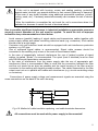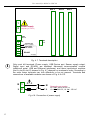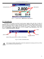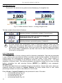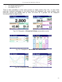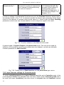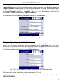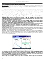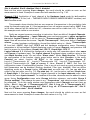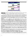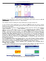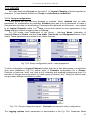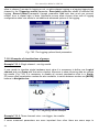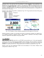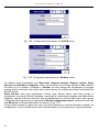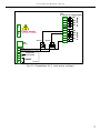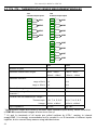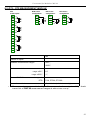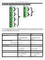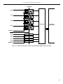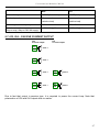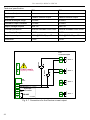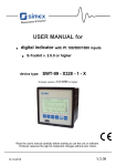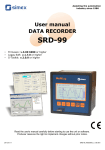
1
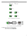
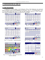
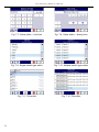
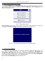
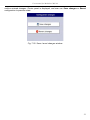
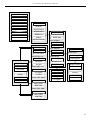
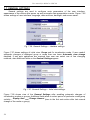
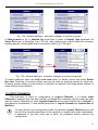
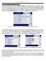
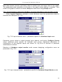
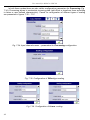
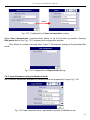
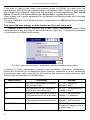
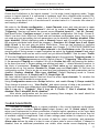
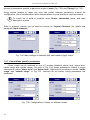
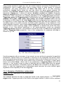
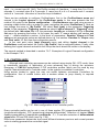
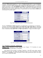
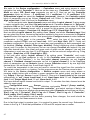
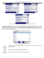
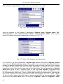
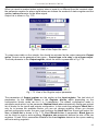
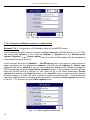
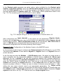
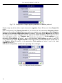
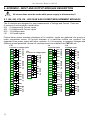
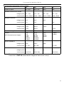
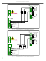
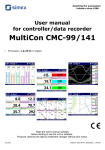
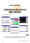
User manual for MultiCon CMC-99
Fig. 7.47. Logical channels configuration - Example 3
Example 7.8.4: Application of input channel in the Hardware output monitor mode for r45, r81
modules (see the Appendix 9.6 r45, r81 - relay modules).
This example consists of reading the value transferred to the output module r45.
To can read the values transferred to the output the CMC-99 should has build-in outputs
module e.g. r45 (except the Sound signal and Virtual relay) and has the logical channel that
controls the output signal.
First of all we have to connect output according to module instruction. Next we can configure
Logical Channels. After entry to Input channels configuration we can configure Logical
Channel. Using arrows in upper navigation bar select Logical Channel 5, and set its name
“Relay 1”. Now we can select the source – e.g. “Out.A1 : Relay” that we want to monitor. Due
to we do not need any post processing its both parameters can be disabled (Scaling:
disabled, Filter type: disabled). Because the output module r45 have binary states so we
change the Format displaying to binary. Accept the default value i.e.: Off-state text: OFF and
On-state text: ON and change data limits: Graph Low: 0, Graph High: 1. We have defined
logical channel. Next exit from the menu Input channels. To visualise the data, channel must
be added to some group.
Using Configuration menu enter Groups definition, and enable Group 1 (Group: enabled).
Then change its name to e.g. “Output monitor”, and select sources of data to be presented.
To do this move window over parameters called Channels and set them as follow Slot 1: Log. ch. 5 “Relay 1”, Slot 2: disabled; Slot 3: disabled, Slot 4: disabled, Slot 5:
disabled; Slot 6: disabled.
After whole configuration exit the menu pressing Save changes, the result should be
visible as soon as first measurement is done. View the example shown in Fig. 7.47.
Fig. 7.48. The proposition of the result the Example 4
49