1
User manual for MultiCon CMC-99
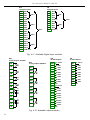
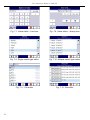
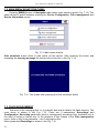
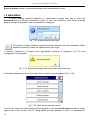
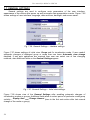
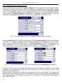
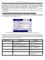
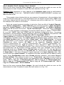
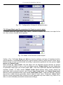
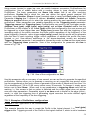
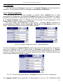
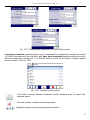
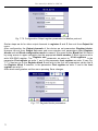
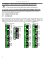
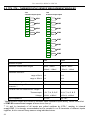
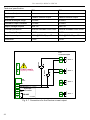
Fig. 7.73. View of the Block list parameter
7.14.1. Examples of Modbus protocol configurations
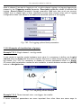
Example 7.14.1: Configuration of the Modbus Input in the MASTER mode.
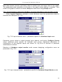
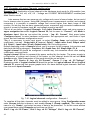
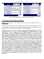
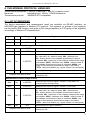
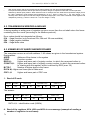
In this example we show how to configure the Input channel of SLAVE device, e.g. for TRS04a device with address 3. We read the Register 1, Register 5 is the Decimal point
register, Register 2 is the Status register which the value of 80h means that the temperature
measurement exceeds the 85ºC.
In the first step we enter the Modbus → SLAVE device menu. We select by using arrows in
upper navigation bar the appropriate address of SLAVE device (address 3). Device type
parameter we set to defined or we can use predefined template with available settings for
TRS-04a device by pressing Load device templates button. In this example we use first case
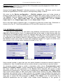
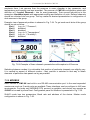
when the SLAVE device is defined by user. Next we go to the block parameters Device
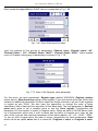
channel and pressing the Input list button. In the Input list menu to open new input channel
we press a button '+'. When we want to delete a channel press the button '-'. After adding the
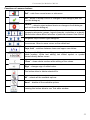
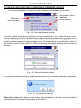
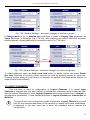
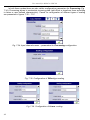
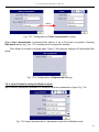
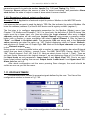
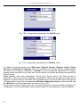
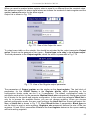
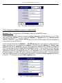
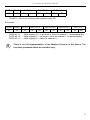
new input channel need to set appropriate parameters. Parameter Value register we set like
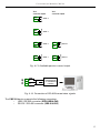
in the Fig. 7.74. Next we exit from Value register menu.
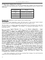
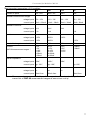
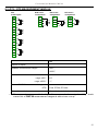
Fig. 7.74. Value register parameters
70