1
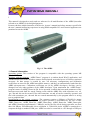
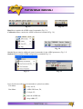
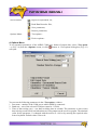
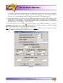
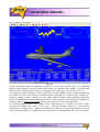
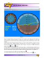
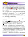
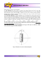
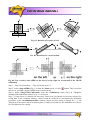
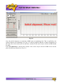
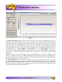
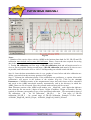
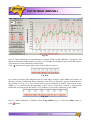
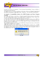
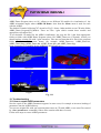
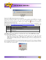
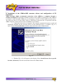
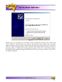
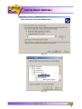
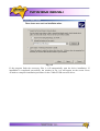
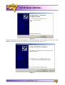
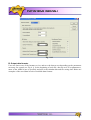
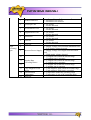
AHRS
DEMO PROGRAM “AHRS DEMO”
Sensor Systems
User’s Manual
2010 Sensor Systems Srl
Revision history
Revisio
n
1.0
1.1 to 2.7
3.0
Date
Author
Description
14-Jun-07
ON
20-Mar-09
ON
Released version.
Skipped
For AHRS Demo Program ver.10.0 and higher.
Work with the AHRS firmware since v.4.1.7.
Updated output data formats (see Appendix B).
Various 3D models for visualization of the AHRS orientation.
Multiple languages support in the program menu, messages
and saved text files.
Table of contents
Introduction
4
1. General information
4
2. Installation of drivers and configuration of PC parameters
5
3. Main menu of the program
6
4. Options Menu
8
5. Run Menu
12
6. Calibration Menu
18
7. Service Menu
20
8. AHRS operation
22
8.1. The main operation modes of the AHRS
22
8.2. Calibration of the AHRS 24
8.3. Conditions of successful calibration of the AHRS
33
9. Continuous self monitoring of the AHRS health
35
10. Control of compatibility between the AHRS firmware and Demo Program
versions
35
11. Choice of 3D model for visualization of the AHRS orientation
37
12. Troubleshooting
38
12.1. How to repair AHRS parameters
38
12.2. What do you have to do when AHRS strange behavior is detected
39
12.3. What do you have to do when message “The parameters are transferred with a
mistake!!”
39
12.4. Why do you can’t write to or read from file in one of the AHRS Demo menu?
40
Appendix
42
A. Installation of the COM-to-USB converter drivers and configuration of PC
parameters
42
B. Output data formats
50
C. The Unit Status Word definition
52
Introduction
This manual is designed to study and use software for all modifications of the AHRS (hereafter
referred to as AHRS) for its designed purposes.
Persons who have studied structure of the device, its user’s manual and safety measures specified in
the user’s manual and having experience in using IBM-compatible PCs and electrical appliances are
permitted to use the AHRS.
Fig. 1.1. The AHRS
1. General information
Operating system. This version of the program is compatible with the operating system MS
Windows XP.
Working with the program. “AHRS Demo” program is a window-based Win32 application, and
standard means used in the Windows (mouse and keyboard) are needed to use it. Directory structure
necessary for data storage is created by user. All necessary configurations and calibration
coefficients are stored in the AHRS nonvolatile memory, and they are automatically loaded into the
AHRS microprocessor. Calibration coefficients are set by AHRS developers, and they can be
changed, but only under guidance of the AHRS developer. Upon termination the “AHRS Demo”
program creates an AHRS_Demo.ini file for its operation, in which the latest used parameters of the
microprocessor and shell are stored. During work with the AHRS files with extensions .txt, .rtf,
.par, .dat and .bin can be created. Files with extensions .txt and .rtf can be created by operator, and
files with extensions .par, .dat and .bin are created automatically by the program when it is saving
text or graphical data.
Requirements to the system resources. The program requires 6 Mbytes of RAM for proper
operation. Hard disk capacity required for proper operation is determined by the size of files
AHRS_Demo.exe, AHRS_Demo.ini, AHRS_Demo.bmp, AHRS_Demo.dat, AHRS_Demo.glm,
and AHRS_Demo.lng approximately 5 MBytes, and by the files saved during operation, no more
than 100 Mbytes. Recommended screen resolution is 1280х1024 pixels. AHRS is connected to a
computer through a standard COM port. AHRS can also be connected to a PC through a USB port
with a COM-to-USB converter. In this case, reliability of signal reception/transmission between a
PC and the AHRS can greatly depend on the quality of the COM-to-USB converter and on correct
configuration of its driver. AHRS manufacturer guarantees reliable operation of the AHRS if it is
connected directly to the COM port. In the Appendix A, installation and configuration of drivers for
one of the possible COM-to-USB converters are described.
Requirements to operators. AHRS software uses a standard Windows operating system. Therefore,
operators should know the basic principles of PC operation to use the program, and they should be
able to use the Windows operating system.
2. Installation of drivers and configuration of PC parameters
Installation of the program. To install the program copy 6 files AHRS_Demo.exe,
AHRS_Demo.ini, AHRS_Demo.bmp, AHRS_Demo.dat, AHRS_Demo.glm, and AHRS_Demo.lng
to the working directory.
When you connect the AHRS to a standard computer COM port, drivers are not installed. If the
AHRS is connected to a USB port using a COM-to-USB converter see “Appendix A. Installation of
the COM-to-USB converter drivers and configuration of PC parameters” for more details.
To know the numbers of the PC COM ports press «Device Manager» in the «Hardware» tab of
the «System Properties» window (Fig. 2.1). In the opened «Device Manager» window (Fig. 2.2)
you will see the COM ports which will be marked as «Communication Port (COMN)». Number
N in the port name is assigned by computer.
Fig. 2.1
Fig. 2.2
3. Main menu of the program
Main menu of the AHRS Demo program (see Fig. 3.1) contains the following sections.
File Menu contains standard Windows file management command (Fig. 3.2).
Fig. 3.1
Fig. 3.2
Run Menu contains the AHRS control commands (Fig. 3.3).
Calibration Menu contains the AHRS calibration command (Fig. 3.4).
Fig. 3.3
Fig. 3.4
Service Menu contains additional control commands for the AHRS parameters (Fig. 3.5).
Options Menu contains AHRS configuration commands Fig. 3.6.
Fig. 3.5
Icons for the most often used commands are placed on toolbar.
File Menu:
- Exit, Alt+X;
Run Menu:
- AHRS 3D Demo, F4;
- Cockpit, F5;
- Start the AHRS run;
- Stop AHRS, F7;
Fig. 3.6
Service Menu:
- Report of experiment, F8;
- Read Data Recorder files;
- Save parameters;
- Restore parameters;
Options Menu :
- Test options...
- Device options...
4. Options Menu
To set operation parameters of the AHRS, COM port, format of output data, select «Test option
…» (Fig. 3.6) from the «Options» menu, or click
will open.
button. A «Test option» dialog box (Fig. 4.1)
Fig. 4.1
You can set the following parameters in the «Test option» window:
1. Port name – number of the COM port to which AHRS is connected.
2. Baud rate – rate of the selected COM port (must be 115200).
3. Time of data writing (sec) – sets data recording time in seconds. The parameter is active when
data is being saved to disk and when data are being output on the screen as graphs. The minimal
value for the parameter 1 is changed with the arrows to ±100 or by entering the required value
from a keyboard. Default value is set to 60.
4. Number data for average – the quantity of averaged data. This can be used for smoothing of
viewed data. Note that averaging relates to the data output on the screen only and is not applied
to the data written in a file. The minimal value for the parameter is 1 and changed with the
arrows to ±1 or by entering the required value from a keyboard. The default value is 1.
5. Output Data Format – sets format of the AHRS output data. Select one of the formats: «Full
Output Data», «Orientation + Incremental Sensor Data», «Quaternion of Orientation»,
«Orientation + Sensor Outputs». For more information on the output data format see Appendix B.
The default value is «Orientation + Sensor Outputs».
To set and control of the AHRS operation parameters, select «Device option …» from the
«Options» menu (Fig. 3.6), or click
button (Fig.3.1). A «Device option…» (Fig. 4.2) dialog
box will open that allow you to set the following parameters.
Note: you are able to select «Device option …» item only if AHRS is powered and connected to
computer, and СОМ port number is chosen properly (see below).
Fig. 4.2
6. Measurement rate (Hz) – sets data measurement rate in Hertz. Minimal value of the parameter is
1, maximal value is 100; it is changed with the arrows to ±10 or by entering the required value
from a keyboard. Default value is set to 100.
7. Initial alignment time (sec) – sets the initial alignment time in seconds. This parameter is active
only for the AHRS standard operation mode, i.e. data in respective windows will be displayed
only after the time set in this parameter is over. During initial alignment the AHRS must be
absolutely unmovable relative to the Earth. Minimum value of the parameter is 1, and it can be
changed to ±1 with arrows or by entering the necessary value from a keyboard. Default value is
set to 60.
8. Device name – the serial number of the AHRS in use. This parameter can not be changed.
9. Device firmware version – the firmware version of the AHRS in use. It consist of symbols of
the firmware type, firmware version and date of this version issue separated by blanks. This
parameter can not be changed.
10. Magnetic declination (deg.) – magnetic declination at the place where the AHRS operates. The
parameter value is changed by entering the required value from a keyboard or by automatic
calculation «Auto calculation» on the basis of Latitude, Longitude and Altitude values. Default
value is set to 0.
11. Latitude (deg.) – latitude of the AHRS operating location.
12. Longitude (deg.) – longitude of the AHRS operational location.
13. Altitude (meters) – altitude above sea level of the AHRS operational location.
14. Year, Month, Day – year, month and day when the AHRS is used. Changed with arrows to ±1
or by entering the required value from a keyboard. Default value is set according to «Properties:
Date and time» of the computer in use.
15. Alignment angles (deg.) – angles between the AHRS axes and the carrier object are set after
AHRS mounting. See “ADM-E2-M-AHRS User’s Manual”, section 4.4. Default values are set
to 0 degrees.
Before working with the «Options» menu, it is desirable to select «Stop “AHRS”» in the «Run»
menu or press F7 key (Fig. 3.3).
Note: You need to set current longitude, altitude, year, month, day only if you want to calculate
magnetic declination for current place and date.
5. Run Menu
Control of the AHRS and control of the parameters input through measurement channels is done by
the commands in the «Run» menu (Fig. 3.3). This menu contains next items:
• “AHRS 3D Demo” and “Cockpit“ select one of two styles of visualization of the AHRS
orientation angles and open appropriate window;
• “Start” starts work of the AHRS in the main mode;
• “Stop AHRS” stops the AHRS;
Below is explanation of these items.
• AHRS 3D Demo opens window in which current orientation angles of the AHRS are
presented as a spatial orientation of an airplane (see Fig. 5.1). To go to this visualization
stile select «AHRS 3D Demo» from the «Run» menu (Fig. 3.3) or click
button on the
toolbar.
Some additional 3D models may be used for visualization of the AHRS orientation (see below
Section 11. Selecting 3D model for visualization of the AHRS orientation).
When “AHRS 3D Demo” window open, three new control buttons («Start»
«Graphs»
, «Write»
and
) appear in the right side of the toolbar.
«Start» button
starts the AHRS with parameters saved in the AHRS’ microprocessor. Next
Initial alignment of the AHRS is performed with displayed message «Initial alignment. Please
wait». During the initial alignment the AHRS has to be unmovable relative to the Earth. Once the
initial alignment time is over, observe changes in numeric data and graphical evolutions of the
airplane.
Note. For visual convenience of the AHRS position perception displayed on the monitor and the
AHRS real position, it is recommended to place the AHRS in parallel with the monitor before the
beginning of work as follows: direct lateral axis X to the monitor and direct longitudinal axis Y in
parallel with the monitor on the left.
Once the «Start» button is pressed, it changes its name to «Stop»
. Upon clicking the «Write»
button
the measured data are saved, which is signified by the message «Data are writing in
file!». Note that the data are saved in binary format. To convert them into text format use «Report
of experiment» from «Service» menu. «Stop» button
saving procedure with no data losses.
stops data output to the screen and data
Fig. 5.1
Current orientation angles are displayed in the lower part of the window (Fig. 5.1). Additional
displayed data depend on selected output data format (see Appendix B for details). If «Full Output
Data» format is chosen then next data are displayed in the lower part of the window (Fig. 5.1):
a) Orientation angles «Heading», «Pitch» and «Roll». In the «AHRS» column, angles calculated in
the AHRS microprocessor using the embedded main algorithm are output. In the «Magn/Acc»
column orientation angles calculated in the AHRS Demo Program using simplified algorithms
based on magnetometers and accelerometers data are output. Angles in the «Magn/Acc» column are
auxiliary; they are used by developers only to control operation of the main algorithm.
b) Calibrated output signals of the AHRS sensors: «Rate (deg/sec)» – angular rate values in deg/s
measured by angular rate sensors, «Accel (g)» – linear acceleration values in g measured by
accelerometers, «Magn (nT)» – magnetic field intensity values measured by magnetometers in nano
Tesla. All sensors data are in AHRS axes (X is lateral axis, Y is longitudinal axis, Z is vertical axis).
c) Current temperature values «Temperature(degC)» inside the AHRS’ sensors (angular rate sensors
«Gyros», accelerometers «Accel» and magnetometers «Mag» respectively).
d) The set value of the magnetic declination «Mdec».
e) Input supply voltage of the AHRS in Volts DC «Vdd».
f) Total measured magnetic field value in nanoTesla «Total magnetic field».
g) Format of output data «Output Data Format: …..». The format is set by operator in the «Test
option» window (Fig. 4.1).
For visualization of the AHRS outputs there are graphs in the upper part of the window. To call the
graphs click the
button. As a result the «Plots» window (Fig. 5.2) will appear. In the middle part
of this window select the signals you want to display:
• Gyros – plots output signals of the gyros X, Y, Z in deg/sec;
• Accelerometers – plots output data of the accelerometers X, Y, Z in g;
• Magnetometers – plots output data of the magnetometers X, Y, Z in nT;
• Umag (raw data) – plots output data of the magnetometers X, Y, Z in ADC codes;
• Module mag – plots full module of the measured magnetic-field vector in nT;
• Angles (AHRS) – plots Heading, Pitch and Roll angels calculated by main algorithm in the
AHRS, in degrees;
• Angles (Acc/Mag) – plots Heading, Pitch and Roll angels calculated by simplified algorithm
in the AHRS Demo Program, in degrees.
For confirmation of plot output check the «View plots» box. Uncheck the box if you don't want
plot.
Fig. 5.2
If other then «Full Output Data» data format is chosen then only proper data will be displayed in the
lower part of the window (Fig. 5.1). But in any case orientation angles are always displayed.
If actual angular rate during operation exceeds gyros range, a warning message «Angular rate is
exceeded: XYZ» is displayed under the image specifying the axis (axes) along which it is exceeded.
The warning message about the AHRS state appears under the main image if any AHRS failure is
detected. This message is generated in accordance with the Unit Status Word (see Appendix C) that
continuously produced by the AHRS.
To stop data output from the AHRS click the «Stop» button
.
To exit from this visualization mode select again “AHRS 3D Demo” from «Run» menu or press
button «F4». Instead this you can simple click
•
icon.
Cockpit – opens window allowing to show current attitude of the AHRS in «Cockpit
display» style (see Fig. 5.3). To start operation in this mode select «Cockpit» in the «Run»
menu (Fig. 3.3) or click «Cockpit»
5.3 will appear.
button on the toolbar, and window shown in the Fig.
Fig. 5.3
There is heading indicator in the upper left corner of the window. In the right part of the window an
attitude indicator (artificial horizon) is shown. Its vertical scale corresponds to pitch, limb
corresponds to roll. Current values of the orientation angles are shown in the left lower corner of the
window.
Control buttons and information messages shown in “Cockpit” mode completely coincide with ones
in the operation mode “AHRS 3D Demo” described above. Also there is a possibility to switch
between operation modes “AHRS 3D Demo” and “Cockpit” at any time of AHRS operation by
simply clicking
button or
button.
If actual angular rate during operation exceeds gyros range, a warning message «Angular rate is
exceeded: XYZ» is displayed under the image specifying the axis (axes) along which it is exceeded.
The warning message about the AHRS state appears under the main image if any AHRS failure is
detected. This message is generated in accordance with the Unit Status Word (see Appendix C).
To stop data output from the AHRS click the «Stop» button
.
To exit from operation mode select again “Run” menu select “Cockpit”, or click
icon.
•
Stop AHRS – stops the AHRS. In most cases it is used for correct termination of completed
operations. For this command the hot key F7 can be also used or button
can be clicked.
6. Calibration Menu
The AHRS software allows to take into account influence of the carrier object soft and hard iron on
the heading angle determination accuracy. For this purpose, field calibration of the AHRS
magnetometers is provided. This calibration does not require any additional equipment, but it
requires turns of the carrier object, on which the AHRS is mounted.
To activate this type of calibration select «Calibration» menu and then «Mag Field Calibration»
command (Fig. 3.4) from the main menu. «Magnetic channel field calibration» (Fig. 6.1) window
will open.
First set time in the «Accumulation Time» window which is need to perform calibration procedure
including at least one full 360° turn rotation in horizon plane (3…5 full turns are recommended).
This time can be set using arrows or by entering the necessary value from a keyboard. The default
value is 60.
You can choose type of the calibration – 2D, 2D+2D or 3D.
Optional «Temperature» window shows temperature inside accelerometers and magnetometers
during calibration.
2D calibration is designed for carrier objects that moves with small pitch and roll angles (not more
than a few degrees). The calibration procedure involves a few full 360° rotations in the horizon
plane of the carrier with the installed AHRS. During this calibration pitch and roll angles must be as
close to zero as possible.
3D calibration is designed for carrier objects that can operate with large pitch and roll angles. For
this calibration the carrier object is rotated in the horizon plane (the Z-axis is up) with periodical
stops about each 90 degrees for tilting in pitch and roll. After full 360° rotation the carrier with the
AHRS is turned over (the Z-axis is down) and the procedure described above should be repeated.
During this calibration the range of pitch and roll angles changing must be as much as possible.
Special 2D+2D calibration is a partial substitution for 3D calibration for carrier objects that can
operate with large pitch and roll angles, but does not allow to perform full 3D calibration procedure.
The 2D+2D calibration repeats above 2D calibration procedure with the AHRS Z-axis up and then
sideways
on
the
left
(-90° Roll) or on the right (+90° Roll) (to set this please use switch «L / R» in window Fig.6.1).
Fig. 6.1
For better perception of calibration results, graphs of errors before and after the calibration
procedure are visualized in different colors, and there is a legend in the bottom of the graph, under
the Time axis, assigning graph colors to specific types of calibration. Click «Accept Parameters»
button (Fig. 6.1) to calculate a calibration matrix for magnetometer biases and scale factors and
save it to the nonvolatile memory of the AHRS. See section 8.2 for detailed description of the
AHRS calibration procedure.
If place of the AHRS mounting on the carrier object is changed, or if the carrier object is changed,
calibration matrices for magnetometer biases and scale factors in AHRS memory should be cleared
by clicking on the «Clear Parameters» button (Fig. 6.1).
7. Service Menu
«Report of experiment» command is used for conversation of saved binary data to text file. When
«Report of experiment» command is selected, or button
is clicked, or «F8» is pressed (Fig. 3.5),
a standard Windows «Open» window is opened; in this window operator selects one of the .bin files
saved previously when the AHRS was operating in its standard mode. Consequently, a report file
with .txt extension is created. When a file with extension .bin is selected, a file of the same name
with an extension .par should be present as well.
«Read Data Recorder files» command (Fig. 3.5) is used to read test data saved in memory of
AHRS Data Recorder. See “AHRS Data Recorder. Users Manual” for detailed information.
«Save parameters» command (Fig. 3.5). If you have changed some parameters of the AHRS (in
«Device options…» window from the «Options» menu), and you want to save these parameters as
variant for future work, you can save the AHRS current parameters in binary file with .par
extension. For this use «Save parameters» command or click button
. After that a standard
Windows «Save as …» window is opened; in this window operator is suggested to save current
parameters of the AHRS to a «File of parameters» with .par extension.
«Restore parameters» command (Fig. 3.5) is used to quickly load the AHRS parameters to the
AHRS nonvolatile memory. When «Restore parameters» command is selected, or button
is
clicked, a standard Windows «Open» window opens; in this window operator selects one of the
previously saved files with .par extension. Consequently, the parameters are automatically saved to
the AHRS nonvolatile memory and to the Demo-Program shell. The same way is used to restore the
factory settings of the AHRS parameters. In this case you should select original file with .par
extension that comes on CD with AHRS.
8. AHRS operation
8.1 The main operation modes of the AHRS
Step 1. Connect a power cable and data transfer cable to the AHRS. Connect the other end of the
data transfer cable to either COM port or USB port of the host computer. If connection between the
computer and the AHRS is done through a USB port, a driver for a COM-to-USB converter needs
to be installed. See Appendix A ‘Installation of the COM-to-USB converter drivers and
configuration of PC parameters’ for details on the installation procedure. If it is connected to a
standard PC COM port, then there are no needs to install any drivers. Note that AHRS manufacturer
guarantees reliable operation of the AHRS if it is connected directly to the COM port.
Step 2. Start AHRS_Demo.exe file to begin working with the Demo program. The main menu will
appear (Fig. 3.1).
Step 3. Select «Test options…» from the «Options» menu (see Fig.3.6) or click
button. «Test
option» window (Fig.4.1) will open.
Step 4. Set the correct СОМ port number «Port name:» and check that its rate «Baud rate» is set
to 115200 as it Fig.4.1 shows.
Step 5. (Not obligatory) In «Test option» window (Fig.4.1), if you need, you can set «Time of data
writing (sec) » which sets data recording time when data is being saved to file. Also you can set
«Number data for average» (the quantity of averaged data) that can be used for smoothing of
viewed data. Note that averaging relates to the data output on the screen only and is not applied to
the data written in a file.
Note. For the number of the СОМ port which the AHRS is connected to, see «2. Installation of
drivers and configuration of the PC parameters» and «Appendix А. Installation of the COM-to-USB
converter drivers and configuration of the PC parameters».
Step 6. In «Test option» window (Fig.4.1) set (check) «Output Data Format» (see Appendix B for
more information on the output data format). Click «ОК».
Step 7. (Not obligatory) If you want to change some parameters of the AHRS select «Device
options …» from the «Options» menu (or click
button) – see Fig.3.6. «Device options…»
window (Fig.4.2) will open. Set the necessary AHRS operation parameters. Click «ОК».
Step 8. Select «Cockpit» from the «Run» menu (Fig. 3.3) or click
button on the toolbar (Fig.
3.1). The window shown in Fig. 5.3 will appear.
You can switch to other visualization mode by selecting «AHRS 3D Demo» from the «Run» menu
(Fig. 3.3) or clicking
will appear.
button on the toolbar, or pressing «F4». The window shown in Fig. 5.1
Step 9. Click «Start»
button. Initial alignment of the AHRS will start. This is signified by the
message «Initial alignment. Please wait. ». During the initial alignment the AHRS has to be
unmovable relative to the Earth. Once the initial alignment time is over, observe changes in numeric
data and graphical evolutions of the object. Once the «Start»
button is pressed, it changes its
name to «Stop»
.
Notes
1. For visual convenience of the AHRS position perception displayed on the monitor and the AHRS
real position, it is recommended to place the AHRS in parallel with the monitor before the
beginning of work as follows: direct lateral axis X to the monitor and direct longitudinal axis Y in
parallel with the monitor on the left.
2. For visualization mode “AHRS 3D Demo” only. Click
button. The «Plots» window (Fig.5.2)
will appear. If you want to show graphs, check the «View plots» box. Select parameters you want to
display and click «ОК». Graphs with chosen parameters will be displayed in the upper part of the
window. To end plotting uncheck «View plots» in the window «Plots» (Fig. 5.2) and click «ОК».
Step 10. To save data click «Write»
button. Caption «Data are writing in file!» will appear.
Also a progress bar of data writing and timer will appear in the status line of the main window.
Step 11. To stop readout and data displaying click «Stop»
button. If the data were written in a
file then the writing stops too.
Default name of file with saved data is generated automatically and consists of the AHRS serial
number, date and time digits separated by dash symbols where the first 4 digits are the year, the
next 2 digits are the month, then 2 digits of day, next digits are hours and minutes of operation. At
the saving data, two files of the same name with .bin and .par extensions are saved in the specified
folder. In .bin files the measured data is saved, and in .par files the AHRS microprocessor
parameters, at which this data was obtained, are saved. For example, "A2200135-2009-06-17-1230.txt" corresponds to data saved from device number A2200135 on 2009, June 17th at 12:30.
Note. You can preset name of file for data writing. For this select item «Save as» in the «File»
menu and enter desirable file name.
Step 12. Repeat Step 9 – Step 11 as many times as you need.
Step 13. To close standard operation mode window (Fig. 5.3) select «Cockpit» from the «Run»
menu (Fig. 3.3), or click
button on the toolbar (Fig. 3.1). To close standard operation mode
window (Fig. 5.1) select «AHRS 3D Demo» from the menu «Run» (Fig. 3.3), or click
or press key «F4».
button,
Step 14. Select «Stop AHRS» (Fig. 3.3) from the «Run» menu, or click
button.
To get the saved data as text file, do the following:
Step 15. Select «Report of experiment» from the «Service» menu (Fig. 3.5) or press «F8» in the
main menu or click
button (Fig. 3.1). A standard Windows «Open» window will open.
Step 16. Select the necessary file with extension .bin. Click «ОК». A .txt file will be created with
the same name and in the same folder as the selected .bin file, with format set in Step 6.
Note. When large file data is processed then some time is necessary for text file saving. If you will
start new operations with program before end of text file saving, then program will appear as not
responding or locked. Just wait some time for saving end, after that program will be unlocked.
8.2 Calibration of the AHRS
For correct operation of the AHRS it is necessary that the calibrated sensors are not distorted by
external influences. It is particularly important to provide non-distortion of the AHRS magnetic
channel, as, due to the presence of the carrier’s hard and soft iron in the vicinity to the AHRS, its
magnetometers will be outputting inaccurate data on the actual Earth magnetic intensity vector, and,
accordingly, inaccurate carrier’s heading angle value.
The AHRS software allows compensation of influence of the carrier object soft and hard iron on the
heading angle determination accuracy. For this purpose, field calibration of the AHRS
magnetometers is provided. This calibration does not require any additional equipment, but it
requires turns of the carries object on which the AHRS is mounted.
2D calibration is designed for carrier objects that moves with small pitch and roll angles (not more
than a few degrees). The calibration procedure involves a few full 360° rotations in the horizon
plane of the carrier with the installed AHRS (see Fig. 8.1). During this calibration pitch and roll
angles must be as close to zero as possible.
For 3D calibration the carrier object is rotated in the horizon plane (the Z-axis is up) with
periodical stops about each 90 degrees for tilting in pitch and roll (see Fig. 8.1; 8.2; 8.3). After full
360° rotation the carrier with the AHRS is turned over (the Z-axis is down) and the procedure
described above should be repeated. During this calibration the range of pitch and roll angles
changing must be as much as possible.
Special 2D+2D calibration is partial substitution for 3D calibration for carrier objects that can
operate with large pitch and roll angles, but does not allow to perform full 3D calibration procedure.
At the first half of the 2D+2D calibration it repeats above 2D calibration procedure with the AHRS
Z-axis up. At the second half of the 2D+2D calibration the carrier with AHRS should be put on its
left side (-90° Roll) or right side (+90° Roll), see Fig. 8.4. Repeat again a few full 360° rotations in
the
horizon
plane
of
the
carrier.
Please
use
switch
«L / R» in window Fig.6.1 to set correctly to what side (left or right) the AHRS will be put.
Note that rotation of the carrier object with the AHRS both for 2D and 3D calibration must include
one or more full 360° turns in the horizon plane.
Field calibration procedures may be specified by after type of the object, on which the AHRS
will be installed, is agreed on with a customer.
Fig. 8.1. Rotation of a carrier in horizontal plane
–γ
Z
X
+γ
Fig. 8.2. Rotation of a carrier in roll
+θ
Y
–θ
Fig. 8.3. Rotation of a carrier in pitch
Fig. 8.4. Put a carrier with AHRS on the left or on the right for second half of the 2D+2D
calibration
Step 1 – Step 4. Perform Step 1 – Step 4 from the item 8.1.
Step 5. Select «Stop AHRS» (Fig. 3.4) from the «Run» menu, or click
button. This is need for
any case if you didn’t stopped AHRS work at previous run.
Step 6. Select «Mag Field Calibration» from the «Calibration» menu (Fig. 3.4). «Magnetic
channel field calibration» window (Fig. 6.1) will open.
Step 7. Using arrows or entering the necessary value from a keyboard set the time required for
saving data to the computer memory, which would be sufficient to accomplish the calibration
procedure, in the «Accumulation time» window. Please set time which is enough for 1…3 full
360° turns of the carrier object in horizon plane. Usually 60 seconds for 2D calibration and 120 sec
for 3D calibration are enough.
Step 8. Select «2D calibration», «2D+2D calibration» or «3D calibration». For «2D+2D
calibration» select also switch «L / R» in window Fig.6.1 to set correctly to what side (left or
right) the AHRS will be put at second stage.
Step 9. Click «Accumulate Data». After that new window “Magnetic channel field calibration
source type” (Fig. 8.5) will appear over initial window Fig.6.1. This window asks to choose the
source of the calibration data.
Fig. 8.5
If «From file» variant is selected then the calibration data will be read from a file created at
previous calibration procedure. This may be useful if you want to load to the AHRS the calibration
parameters that corresponds to one of its earlier calibrations. At this a standard MS Windows
«Open» window is opened in which you may select one of the previously created files with .amd
extension.
Filename consists of the AHRS serial number, text _ MagField _ and 6 digits that indicates time
when the file was saved (2 digits of hours, 2 digits of minutes, 2 digits of seconds). The last
symbols in filename corresponds to type of the calibration:
_2D corresponds to data of 2D calibration;
_3D corresponds to data of 3D calibration;
_2D+2D_1 corresponds to data of first stage of 2D+2D calibration;
_2D+2D_2 corresponds to data of second stage of 2D+2D calibration;
Example of filename: A2200001_MagField_140838_2D.amd. It means that this file contains 2D
calibration data for AHRS # A2200001 saved at time 14:08:38.
If «From AHRS» variant is selected in the window Fig.8.5 then the calibration data will be get
from the AHRS (default variant). Initial alignment of the AHRSwill start, signified by the caption
«Initial alignment. Please wait.» (Fig. 8.6). During the initial alignment, the AHRS shall be
unmovable relative to the Earth.
Fig. 8.6
Once the initial alignment is completed, AHRS starts accumulating data. This is signified by the
caption «Data are accumulating» (see Fig. 8.7) and the graphical indicator of data accumulation in
the status line of the main menu. At this time, rotation of the carrier object with the AHRS should
be made.
If the 2D calibration is chosen then rotation of the carrier object with the AHRS in the horizon
plane should be performed (see Fig. 8.1).
Fig. 8.7
The 2D+2D calibration consists of two stages. First stage is the same as 2D calibration. After time
of the first stage of the AHRS rotation will be reached (or name of file with first stage calibration
data will be entered) the prompt message «Rotate Device!» will appear (see Fig. 8.8). For second
stage the carrier with AHRS should be put on the left or right side (in accordance with selected
switch «L / R»). Click «OK» button on window Fig. 8.8. After this a window “Magnetic channel
field calibration source type” (like in Fig. 8.5) will appear where you should choose the source of
the calibration data – «From AHRS» or «From file». In case of «From AHRS» variant rotate
again the carrier object with the AHRS in the horizon plane. In case of «From file» variant please
select file like *_2D+2D_2.amd that contains early saved data of second stage of the 2D+2D
calibration.
Automatic saving data after first stage of the 2D+2D calibration (to file like *_2D+2D_1.amd)
allows to temporary interrupt the AHRS calibration after first stage (and switch off AHRS if it is
need) for placing object on the left or right side. After that you may continue the 2D+2D calibration
procedure using saved file as first stage data.
For 3D calibration the carrier object is rotated in the horizon plane (the Z-axis is up) with
periodical stops about each 90 degrees for tilting in pitch and roll (see Fig. 8.1; 8.2; 8.3), and then
the carrier with the AHRS is turned over (the Z-axis is down) and the procedure described above
should be repeated. Tilt angles range depends on the carrier object, but to obtain the better result
increase the angles range as much as possible.
Fig. 8.8
Notes:
1. Rotation of the carrier object with the AHRS in the horizon plane both for 2D, 2D+2D and 3D
calibration must include one or more full 360° turns. Please, correct the time required for saving
data in the «Accumulation time» window to attain necessary rotations.
2. During 2D calibration and first stage of 2D+2D calibration pitch and roll angles must be as
close to zero as possible. During second stage o f2D+2D calibration pitch must be as close to zero
as possible, and roll must be close to -90° or +90° depending on selected switch «L / R».
Step 10. Once the data accumulation time is over, graphs of errors before and after calibration are
shown; you can look at the necessary portions of the graphs.
Step 11. Estimate the calibration quality. If the calibration was satisfactory, a caption «Successful
calibration!» will appear in the bottom of the window (Fig. 8.9). Click on the «Accept
Parameters». Calibration matrix of the magnetometer biases and scale factors will be calculated
and saved to the AHRS nonvolatile memory automatically, and in the directory in which the
AHRS_Demo.exe file is located, files with .par and .amd extension will be created.
Note. Filename consists of the AHRS serial number, text _ MagField _ and 6 digits that indicates
time when the file was saved (2 digits of hours, 2 digits of minutes, 2 digits of seconds). The last
symbols in filename corresponds to type of the performed calibration: _2D corresponds to data of
2D calibration; _3D – for 3D calibration; _2D+2D_1 – for
first stage of 2D+2D
calibration;_2D+2D_2 – for second stage of 2D+2D calibration. Example of files name:
A2200001_MagField_140838_2D.par, A2200001_MagField_140838_2D.amd.
Fig. 8.9
Step 12. If the calibration was unsatisfactory, a caption «Unsuccessful calibration. Try again!» will
appear in the bottom of the window (see Fig. 8.10). Number in parentheses at the end of this caption
is residual error of the calibration in nanoTeslas.
Click «×» button in the upper right corner of the window to close it.
Fig. 8.10
One reason of unsuccessful calibration may be small range of angles of the AHRS real rotation. In
this case a caption «Calibration failure! Rotation of the device is required!» appears in the bottom of
the window (see Fig. 8.11). To avoid this please repeat calibration procedure with rotation of the
AHRS as it is described in the beginning of this section. Some more reasons of unsuccessful
calibration are discussed in the section “8.3.Conditions of successful calibration of the AHRS”.
Fig. 8.11
Step 13. When calibration is finished, select «Stop AHRS» (Fig. 3.3) from the «Run» menu or
click
button.
To remove results of field calibration from AHRS memory, follow Step 1 – Step 6. Next click the
«Clear Parameters» button (see Fig. 6.1). Soft and hard iron calibration parameters will be
removed from AHRS memory and window Fig. 6.1 will be closed automatically.
You must clear parameters of the soft and hard iron calibration if you uninstall the AHRS from
carrier object to avoid incorrect heading determination. Please remember that performed soft and
hard iron calibration is valid until the AHRS is mounted on the object with which the calibration
was performed.
When calibration was accepted then during operation with AHRS in the “AHRS Demo” window
(see Fig.5.1) a capture “Soft/hard iron corrected” appears In the lower left part of this window. If
calibration parameters are cleared in the AHRS, then capture “Soft/hard iron corrected” disappears.
Conditions of successful calibration of the AHRS
Success of the AHRS calibration on soft and hard iron of the carrier object essentially depends on
magnetic environment at the place where this calibration is performed.
The best results will be got if calibration is performed in homogeneous magnetic environment
where the magnetic force lines are parallel to each other. In this case only influence of the carrier
object on the AHRS magnetometers take place, and this influence can be compensated after
calibration procedure.
However, magnetic environment often is not homogeneous at place where calibration of the AHRS
is performed. This may lead to degradation of the calibration results since AHRS magnetometers
are disturbed both by iron of the carrier object and by curved outward magnetic field. In this case it
may be very difficult to separate influence of these 2 disturbance sources on the AHRS.
engineers have develop special calibration procedure for separation of these sources of magnetic
disturbance to take into account and compensate just influence of the magnetic field of the carrier
object. But residual influence of non-uniformity of environmental magnetic field may still decrease
calibration accuracy. After a lot of experiments engineers have determined acceptable limits of nonuniformity of environmental magnetic field at which the AHRS heading accuracy after calibration
is satisfactory.
If the AHRS calibration procedure was performed in the strict accordance with procedure described
in section 8.2 but calibration is unsuccessful, then place of the calibration has large distortion of the
Earth uniform magnetic field. To repair this problem please change place of the calibration. For
example, usually bad places for the calibration are office room, laboratory with large quantity of
computers and other electronics equipment, road with underground communications or pipelines,
place near electric mains, etc.
But even in bad magnetic environment the calibration can be successful if AHRS rotates around its
magnetometers (around the point about 15 mm away from the AHRS forward end). In this case
influence of non-uniformity of environmental magnetic field is minimal.
Finally, please remember that if the carrier object is changed or If place of the AHRS mounting on
the carrier object is changed, the new calibration should be performed. If the AHRS will be used
alone without mounting on any object then calibration results should be cleared by clicking on the
«Clear Parameters» button (see Fig. 6.1).
9. Continuous self monitoring of the AHRS health
The AHRS2 with firmware versions since v.33 has continuous built-in monitoring of the AHRS
health. In the main mode the AHRS sends out Unit Status Word (USW) in each data block (see also
Appendix B).
The low byte (bits 0-7) of USW indicates failure of the AHRS. If this byte is 0, the AHRS operates
correctly, if it is not 0, see “Appendix C. The Unit Status Word definition” for type of failure or
contact the developers directly.
The high byte (bits 8-15) contains a warning or is informative for the user. Status of each bit of
the USW warning byte is specified in the “Appendix C. The Unit Status Word definition”.
10. Control of compatibility between the AHRS firmware and Demo Program
versions
New AHRS with firmware version since v.3.2 has also upgraded hardware that gives new features
like input voltage control, control of the AHRS health. For supporting of these features new
versions of the AHRS Demo Program was developed since version 6.0.
It is clear that old versions of the AHRS Demo Program don’t support features of new AHRS. On
the other hand, some functions of the old AHRS Demo Programs were deleted from the new
Program versions (for example, control of the AHRS angular rate range was transmitted from the
Demo Program to the AHRS inside).
We recommend strongly to use version of the AHRS Demo Program that comes on CD with the
AHRS until the AHRS firmware is updated.
AHRS Demo Program ver.10.* works correctly with AHRS firmware versions v.4.1.*. If AHRS
has earlier firmware version then before execution of any command sent from the Demo Program to
the AHRS the warning window appears (see Fig.10.1) that informs about incompatible version of
the AHRS firmware. Click “OK” and continue work.
Fig. 10.1
11. Choice of 3D model for visualization of the AHRS orientation
AHRS Demo Program since ver.10.* allows to use different 3D models for visualization of the
AHRS orientation angles when «AHRS 3D Demo» item from the «Run» menu is used for work
with the AHRS.
The default 3D model is Boeing 747 aircraft as Fig.5.1 shows. Other models are on CD in the folder
AHRS_Demo_Program\3D_Models. There are files *.glm which contain these models and
appropriate screenshot files.
To set desirable 3D model for the AHRS visualization, just copy the file *.glm from appropriate
folder to folder with AHRS Demo Program (where file AHRS_Demo.exe is located). At this you
should replace existing file with *.glm extension. Take into account that all 6 files in the program
folder should have the same names (for example AHRS_Demo.exe, AHRS_Demo.ini,
AHRS_Demo.bmp, AHRS_Demo.dat, AHRS_Demo.glm, and AHRS_Demo.lng).
Some examples of 3D models for the AHRS are shown on Fig.11.1.
Helicopter
Ferrari_F40
Submarine
Clipper
Fig. 11.1
12. Troubleshooting
12.1 How to repair AHRS parameters
Need to repair of the AHRS parameters appears in some cases, for example at incorrect loading of
parameters into the AHRS memory.
You can use original file with .par extension that comes on CD with AHRS, or use own files created
by «Save parameters» command (if these files contain valid data of course).
Follow next steps to restore AHRS parameters.
•
•
Connect the AHRS to PC and power it.
Start the AHRS Demo program. The main menu will appear (see Fig. 3.1).
•
Select «Test options…» from the «Options» menu (or click
button) – see Fig. 3.6. «Test
options» window (Fig. 4.1) will open.
Select the correct СОМ port number and its rate «Baud rate:115200». Click «ОК».
•
Note. For the number of the СОМ port to which the AHRS is connected, see items «2. Installation of drivers
and configuration of the PC parameters» and «Appendix А. Installation of the COM-to-USB converter
drivers and configuration of the PC parameters».
•
Select «Restore parameters…» in the «Service» menu (see Fig. 3.5) or click
button. A
standard Windows «Open» window will open.
Select file with extension .par containing the factory settings of the AHRS parameters or own file
created by «Save parameters» command (if this file contains valid data of course). Click «ОК».
These parameters will be loaded into AHRS memory automatically.
12.2 What do you have to do when AHRS strange behavior is detected
If you see strange behavior of AHRS, first check whose parameters are loaded in the connected
AHRS. This may occur, for example, if you have restored parameters that corresponds to another
AHRS with not proper serial number. Please use «Restore parameters…» command accurately to
avoid wrong parameters loading into the AHRS’s memory.
To check whose parameters are loaded in the connected AHRS please select «Device options …»
from the «Options» menu (or click
button) – see Fig. 3.6. «Device options» window (see
Fig. 4.2) will open.
In the field “Device name” you will see serial number of AHRS (up to 8 symbols). It must
correspond to serial number that is placed on label on AHRS's nose.
If “Device name” doesn’t correspond to serial number of the connected AHRS then you must
restore original parameters as that described in above section.
If “Device name” corresponds to AHRS serial number, but you continue see strange behavior of
AHRS, then this may be due to improper hard/soft iron calibration parameters are loaded into
AHRS’s memory.
If you have removed AHRS from carrier object, then you must clear parameters of soft/hard iron
calibration. To do this follow Step 1 – Step 6 in section “8.2. Calibration of the AHRS”. Next click
the «Clear Parameters» button (see Fig. 6.1). Soft and hard iron calibration parameters will be
removed from AHRS memory and window Fig. 6.1 will be closed automatically.
If you mount AHRS in another place in carrier object, or move it to another carrier object, then you
must repeat soft/hard iron calibration procedure as it described in section “8.3. Calibration of the
AHRS”.
12.3 What do you have to do when message “The parameters are transferred with a
mistake!!”
When you use AHRS Demo program, the most of operations are started with reading data from the
AHRS nonvolatile memory to control correct AHRS status. No problem takes place if AHRS is
connected to computer through a standard COM-port. If you connect AHRS to USB-port using
COM-to-USB adapter then sometimes incorrect reading of the AHRS parameters may occur. In this
case you will see message like Fig. 12.1 shows.
Fig. 12.1
Simply click «OK» button and repeat your operation.
Also above message may appear if you want to do some operations with AHRS but it was not
stopped after previous work. In this case previous program continues its work in AHRS
microprocessor and light indicator in AHRS is green. Simply click
button to stop program in
AHRS (light indicator will be red).
The error code in the message above is the system code received by function “GetLastError”. For
more details see http://msdn.microsoft.com/en-us/library/ms681382(VS.85).aspx . The frequently
occurring error codes are listed in the table below.
Code
Description
0
The mistake cannot be defined.
2
The system cannot find COM-port.
5
Access is denied: the AHRS is occupied, or COM-port is connected to
another device.
87
The COM-port parameters are incorrect.
12.4 Why do you can’t write to or read from file in one of the AHRS Demo menu?
There are two possible reasons
1. You can’t work with the AHRS Demo Program from CD. Just copy files from
AHRS_Demo_Program folder (AHRS_Demo.exe, AHRS_Demo.ini, AHRS_Demo.bmp,
AHRS_Demo.dat, AHRS_Demo.glm, AHRS_Demo.lng) to the any working directory on
PC hard disk.
2. You can not work with file if it is opened by other program on your PC for viewing or editing. In
this case window like Fig.12.2 appears. Just close that other program and repeat operation with file
in the AHRS Demo Program again.
Fig. 12.2
Appendix
A. Installation of the COM-to-USB converter drivers and configuration of PC
parameters
AHRS developer highly recommends connection of the AHRS to a computer through a
standard COM-port for guaranteed reliable operation of the AHRS. If connection of the AHRS to
a computer is done through a USB port, it is necessary to install a COM-to-USB converter driver.
The converter driver is in the folder COM_to_USB_Driver placed on the CD provided with the
AHRS. Sequence of the converter driver installation is as follows:
• Connect the converter to a computer. The computer automatically starts a search and
installation program for the necessary drivers of the connected device. A window (Fig. A.1)
opens. Select «No, not this time» from the menu and click on the «Next» button.
Fig. A.1
• Window (Fig. A.2) will appear on the display. Select «Install from a list or specific
location (Advanced)» from the menu and click on the «Next» button.
Fig. A.2
Window (Fig. A.3) will appear on the display. Check «Include this location in the search:» and
click on «Browse». Show the path to the converter drivers folder in the window (Fig. A.4) which
appears on the top of the previous one (folder name may differ from the name in Fig. A.4) and click
«ОК» (if a folder containing no driver files is selected, «ОК» button will remain inactive). Next, in
the window Fig. A.3, which will be looking like the window in Fig. A.5, a path will be defined.
Using this path the installation program will search for the necessary converter driver. Press «Next»
to continue installation.
Fig. A.3
Fig. A.4
Fig. A.5
If the program finds the necessary files, it will automatically start the driver installation. If
installation is completed successfully, the window in Fig. A.6 will appear on the screen. Press
«Finish» to complete installation procedure for the COM-to-USB converter driver.
Fig. A.6
If the necessary drivers are not installed, an error message (Fig. A.7) will appear. In this case, click
«Back» and set the correct path to the driver files in the window in Fig. A.3.
Fig. A.7
Once the converter driver is installed, you will need to know the number of the additional COMport set by the system and configure parameters of this port for correct operation of the AHRS. To
do this, press the «Device Manager» button in the «System Properties» window (Fig. A.8), in the
«Hardware» tab. In the opened «Device Manager» window (Fig. A.9) the additionally set СОМport will be marked as «USB serial port (COMN)». Number N in the port name will be assigned
by the computer.
Fig. A.8
Fig. A.9
Next, open the Properties window of this port «USB serial port (COMN) Properties» (Fig. A.10)
and press the «Advanced» button. In the opened «Advanced Settings for COMN» window set the
parameters:
*0Latency Timer (msec) to 16;
*1Minimum Read Timeout (msec) to 0;
*2Minimum Write Timeout (msec) to 0;
as it is shown in Fig. A.11, and click «ОК».
Note. set of the “USB serial port (COMN)” parameters that was required for previous versions of
the AHRS Demo Program are also valid:
*3Latency Timer (msec) 1;
*4Minimum Read Timeout (msec) 100;
*5Minimum Write Timeout (msec) 100;
but parameters shown in Fig. A.11 provide less load on CPU of computer.
Fig. A.10
Fig. A.11
B. Output data formats
User can choose one of the formats to view and save the data as text depending on the parameters
necessary for control (see Fig. 4.1). In the beginning of each file, after the text «Test parameters»,
name of the AHRS in use is specified, and next is the calendar date and file saving time. Below are
examples of the saved data in each of available data formats.
C. The Unit Status Word definition
Low
(failure)
Bit
0
Parameter
Initial Alignment
Performance
0 – Successful initial alignment
1 – Unsuccessful initial alignment due to AHRS
byte
High
(warning)
byte
1
AHRS Parameters
2
Gyroscope Unit
3
Accelerometer Unit
4
Magnetometer Unit
5
Electronics
6
Software
7
8
Reserved
9
Incorrect Power Supply
10
11
Angular Rate
Exceeding Detect
12
13
14
15
Large Magnetic Field
Detect
Environmental
Temperature
Reserved
moving or large changing of outer magnetic field
0 – Parameters are correct
1 – Parameters are incorrect
0 – No failure
1 – Failure detected
0 – No failure
1 – Failure detected
0 – No failure
1 – Failure detected
0 – No failure
1 – Failure detected
0 – No failure
1 – Failure detected
0 – Supply voltage is not less than minimum level
1 – Low supply voltage detected
0 – Supply voltage is not higher than maximum
level
1 – High supply voltage detected
0 – X-angular rate within the normal range
1 – X-angular rate is outrange
0 – Y-angular rate within the normal range
1 – Y-angular rate is outrange
0 – Z-angular rate within the normal range
1 – Z-angular rate is outrange
0 – Total magnetic field within the normal range
1 – Total magnetic field limit is exceeded
0 – Temperature within the operating range
1 – Temperature is out of the operating range