1
Developing RSView
Supervisory Edition
Applications
RSView Supervisory Edition 3.0
RSView Supervisory Edition Training Guide
Contacting
Rockwell Software
Technical Support Telephone—440-646-5800
Technical Support Fax—440-646-5801
World Wide Web—www.software.rockwell.com
Copyright Notice
© 2002 Rockwell Software Inc. All rights reserved
Printed in the United States of America
Portions copyrighted by Allen-Bradley Company, Inc. and used with permission.
This manual and any accompanying Rockwell Software products are copyrighted by
Rockwell Software Inc. Any reproduction and/or distribution without prior written consent
from Rockwell Software Inc. is strictly prohibited. Please refer to the license agreement
for details.
Trademark Notices
WINtelligent Series is a registered trademark. The Rockwell Software logo, RSAssistant,
RSBatch, RSCompanion, RSData, RSEmulate 5, RSEmulate 500, RSGuardian,
RSHarmony, RSKeys, RSLinx, RSLogix 5, RSLogix 500, RSPower, RSPowerCFG,
RSPowerRUN, RSRules, RSServer32, RSServer, RSServer Toolkit, RSSql, RSToolbox,
RSTrainer, RSTrend, RSTune, RSView32, RSView, RSWire, A.I. Series, Advanced
Interface (A.I.) Series, AdvanceDDE, ControlGuardian, ControlView, INTERCHANGE,
Packed DDE, PLC-500, WINtelligent, WINtelligent EMULATE 5, WINtelligent EMULATE
500, WINtelligent LINX, WINtelligent LOGIC 5, WINtelligent VIEW, WINtelligent RECIPE,
WINtelligent VISION, WINtelligent VISION2 are trademarks of Rockwell Software Inc.
PLC, PLC-2, PLC-3 and PLC-5 are registered trademarks, and Data Highway Plus, DH+,
DHII, DTL, Network DTL, Pyramid Integrator, PanelBuilder, PanelView, PLC-5/250, PLC5/20E, PLC-5/40E , PLC-5/80E, SLC, SLC 5/01, SLC 5/02, SLC 5/03, SLC 5/04, and
SLC 500 are trademarks of the Allen-Bradley Company, Inc.
Microsoft, MS-DOS, Windows, and Visual Basic are registered trademarks, and Windows
NT and Microsoft Access are trademarks of the Microsoft Corporation.
Ethernet is a registered trademark of Digital Equipment Corporation, Intel, and Xerox
Corporation.
IBM is a registered trademark of International Business Machines Corporation. AIX,
PowerPC, Power Series, RISC System/6000 are trademarks of International Business
Machines Corporation.
UNIX is a registered trademark in the United States and other countries, licensed
exclusively through X/Open Company Limited.
All other trademarks are the property of their respective holders and are hereby
acknowledged.
Warranty
This Rockwell Software product is warranted in accord with the product license. The
product's performance will be affected by system configuration, the application being
performed, operator control and other related factors.
The product's implementation may vary among users.
This manual is as up-to-date as possible at the time of printing; however, the
accompanying software may have changed since that time. Rockwell Software reserves
the right to change any information contained in this manual or the software at anytime
without prior notice.
The instructions in this manual do not claim to cover all the details or variations in the
equipment, procedure, or process described, or to provide directions for meeting every
possible contingency during installation, operation, or maintenance.
Revision Date: 2/13/2006
Covers: RSView Supervisory Edition 3.0
RSView Supervisory Edition Training Guide
i
Table of Contents
1. Course Objectives ........................................................................ 1
2. Introducing RSView Supervisory Edition................................... 1
What is RSView Supervisory Edition?........................................................................... 2
Where to get Help.......................................................................................................... 3
Before You Begin .......................................................................................................... 4
Minimum Hardware and Software Requirements ...................................................... 4
Activating RSView SE Software .................................................................................... 6
RSLinx for RSView ........................................................................................................ 9
Lab 1 – Working with RSLinx ..................................................................................... 12
3. Creating An RSView SE Application........................................... 1
RSView SE - The Distributed Application...................................................................... 2
RSView SE - The Standalone Application..................................................................... 3
Creating an Application ................................................................................................. 4
The FactoryTalk Directory.......................................................................................... 4
Navigating RSView Studio............................................................................................. 7
The View Menu .......................................................................................................... 7
The Status Bar ........................................................................................................... 8
Workbook Mode......................................................................................................... 9
Building a Distributed Application .................................................................................. 9
Areas.......................................................................................................................... 9
HMI Servers and HMI Projects ................................................................................ 10
Building a Standalone Application ............................................................................... 15
Communicating with a processor ................................................................................ 16
Creating and configuring a Data Server................................................................... 16
Data Server Redundancy......................................................................................... 18
Lab 2 – Create a Standalone SE Application ............................................................. 20
4. Communications .......................................................................... 1
Communicating with a processor .................................................................................. 2
Directly Referenced Tags .............................................................................................. 2
Using Directly Referenced Tags ................................................................................ 3
HMI Tags ....................................................................................................................... 5
When to use HMI Tags .............................................................................................. 6
Creating HMI Tags..................................................................................................... 7
The Tag Database Editor........................................................................................... 8
Creating New HMI Tags........................................................................................... 11
The PLC Database Browser........................................................................................ 15
Importing and Exporting the Tag Database................................................................. 17
Lab 3 – Create an HMI Tag Database........................................................................ 20
RSView Supervisory Edition Training Guide
ii
5. Graphic Displays .......................................................................... 1
The Graphic Display Editor............................................................................................ 2
Creating a New Graphic Display ................................................................................... 3
Display Settings ......................................................................................................... 5
Grid, Snap and Zoom................................................................................................. 8
Using Objects in a Graphic Display ............................................................................... 9
Drawing Objects....................................................................................................... 10
The Property Panel .................................................................................................. 11
Arranging Objects .................................................................................................... 12
Converting Objects to Wallpaper ............................................................................. 14
Lab 4 – Basic Graphic Display Elements .................................................................... 15
Adding Objects from the Graphics Library ............................................................... 18
The Object Explorer ................................................................................................. 19
The Tag Browser ..................................................................................................... 21
RSView Commands................................................................................................. 23
Relative and Absolute Referencing.......................................................................... 27
Tag Substitution ....................................................................................................... 28
The Expression Editor.............................................................................................. 29
Interactive Objects....................................................................................................... 31
Push Button Objects ................................................................................................ 33
Numeric and String Objects ..................................................................................... 41
Indicator Objects ...................................................................................................... 42
Gauge and Graph Objects ....................................................................................... 43
Key Objects.............................................................................................................. 44
Advanced Objects.................................................................................................... 45
Lab 5 – Building an Interactive Graphic Display.......................................................... 51
Animating Graphical Objects ....................................................................................... 58
Lab 6 – Animating a Graphic Display .......................................................................... 61
Tag Placeholders and Parameter Files ....................................................................... 71
Displaying Graphics with Tag Placeholders............................................................. 73
Lab 7 – Tag Placeholders in Graphic Displays............................................................ 75
6. Alarms ........................................................................................... 1
RSView Alarm Concepts ............................................................................................... 2
The Alarm Setup Editor.............................................................................................. 3
The Alarm Log Setup Tool ......................................................................................... 7
The Alarm Summary Object..................................................................................... 17
The Alarm Log Viewer ............................................................................................. 18
Suppressing Alarms................................................................................................. 19
Lab 8 – Configuring Alarms ......................................................................................... 20
RSView Supervisory Edition Training Guide
iii
7. Diagnostics Logging .................................................................... 1
FactoryTalk Diagnostics ................................................................................................ 2
FactoryTalk Diagnostics Logging............................................................................... 2
The FactoryTalk Diagnostics Viewer ......................................................................... 7
The RSView Diagnostics List..................................................................................... 9
8. Data Logging................................................................................. 1
Data Log Models........................................................................................................ 2
Starting and Stopping Data Logging ........................................................................ 10
Lab 9 – Data Logging .................................................................................................. 11
9. Trending Data ............................................................................... 1
Creating a Trend ........................................................................................................ 2
Snapshots and Trend Overlays ............................................................................... 10
Creating Trend Templates ....................................................................................... 12
The TrendX Object Model........................................................................................ 16
Lab 10 – Trending ....................................................................................................... 20
10. Derived Tags and Event Files.................................................... 1
Derived Tags ................................................................................................................. 2
Event Files..................................................................................................................... 5
Lab 11 – Derived Tags and Event Files ........................................................................ 8
11. Macros, Symbols and Keys ....................................................... 1
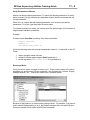
Using Macros................................................................................................................. 2
Using Symbols............................................................................................................... 5
Using Keys .................................................................................................................... 6
Lab 12 – Macros, Symbols and Keys .......................................................................... 10
12. Security ....................................................................................... 1
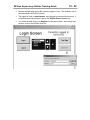
User Accounts ............................................................................................................... 3
Securing the Application................................................................................................ 6
Securing Commands ................................................................................................. 7
Securing HMI Tags .................................................................................................... 8
Securing HMI Graphics.............................................................................................. 8
Login and Logout ....................................................................................................... 9
Electronic Signature Verification.................................................................................. 10
DeskLock..................................................................................................................... 12
Lab 13 – Implementing Security .................................................................................. 15
RSView Supervisory Edition Training Guide
iv
13. VBA Display Code ...................................................................... 1
VBA in RSView SE ........................................................................................................ 2
The SE Client Object Model .......................................................................................... 3
The VBA IDE ................................................................................................................. 5
Lab 14 – Creating VBA Display Code ........................................................................... 8
14. Creating a Distributed Application ........................................... 1
The Distributed Application............................................................................................ 2
RSView SE Client ...................................................................................................... 3
RSView SE Administration Console .......................................................................... 8
RSView SE Command Execution................................................................................ 10
Deploying A Distributed Application ............................................................................ 13
RSView SE Redundancy............................................................................................. 15
FactoryTalk Directory............................................................................................... 15
Data Server Redundancy......................................................................................... 16
HMI Server Redundancy.......................................................................................... 17
Lab 15 – Create a Distributed Application ................................................................... 19
RSView Supervisory Edition Training Guide
1-1
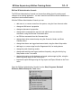
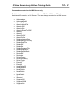
1. Course Objectives
Upon completion of this course, you will be able to develop a working RSView
Supervisory Edition project by performing the following tasks:
•
Understand the architecture of both standalone and distributed RSView
Supervisory Edition applications
•
Create a new application in RSView Studio
•
Create Areas, HMI Servers and Data Servers within an application
•
Configure communications using direct referencing of OPC topics and HMI tags
•
Build an HMI Tag Database by manual entry, Database Browser and Database
Import & Export Wizard
•
Create and run Derived Tag and Event files
•
Create graphic displays
•
Configure Alarming for HMI tags and view it in Alarm Log files and an Alarm
Summary object
•
Configure FactoryTalk Diagnostics Logging and Data Logging
•
Create Trends to show real-time and historical data
•
Configure User Accounts and apply security to graphics, HMI tags and
commands
•
Learn about VBA Display Code and the SE Client Object Model
•
Create a distributed application
•
Configure HMI Server and Data Server Redundancy
•
Deploy a distributed application to multiple computers
•
Configure RSView SE Client and run an application
RSView Supervisory Edition Training Guide
This page intentionally left blank.
1-2
RSView Supervisory Edition Training Guide
2-1
2. Introducing RSView Supervisory Edition
Objectives:
•
Understand where RSView Supervisory Edition fits into the ViewAnyWare
strategy
•
Understand the different software packages needed for developing and running
Supervisory Edition applications
•
Understand the minimum hardware and operating system requirements for the
Supervisory Edition development and runtime environments.
•
Understand how to activate your software
•
Understand the general features and functions of an RSView Supervisory Edition
application.
RSView Supervisory Edition Training Guide
2-2
What is RSView Supervisory Edition?
RSView Supervisory Edition is a product in the ViewAnyWare strategy from Rockwell
Automation. ViewAnyWare is a complete visualization effort encompassing both
hardware and software. ViewAnyWare provides a single development environment to
create visualization solutions that span from small machine level to large supervisory
level projects.
The RSView Enterprise Series refers to the software foundation of ViewAnyWare. The
Enterprise Series consists of RSView Studio, RSView Machine Edition and RSView
Supervisory Edition.
RSView Supervisory Edition consists of several pieces of software you can use to build
powerful automation applications. These applications can be distributed among multiple
servers and clients. Depending on the particular software package(s) you purchased
and installed, you might have one or more of these pieces of software:
RSView Studio is configuration software for developing and testing machine- and
supervisory-level human-machine interface (HMI) applications. RSView Studio contains
editors for creating a complete human-machine interface application, and contains
software for testing the applications you create. Use the editors to create applications
that are as simple or as sophisticated as you need.
RSView SE Client is runtime software for viewing and interacting with supervisory-level
applications developed using RSView Studio.
RSView SE Server stores HMI project components (for example, graphic displays), and
serves these components to clients. The server also contains a database of tags, and
performs alarm detection, and historical data management (logging). The RSView SE
Server has no user interface. Once installed, it runs as a set of ‘headless’ Windows
services that supply information to clients when they request it.
FactoryTalk Directory is software that allows the parts of a distributed application to
find each other on the network. For example, to access the HMI projects on HMI servers
in the application, SE clients use the FactoryTalk Directory to find out which computers
on the network are hosting HMI servers. The FactoryTalk Directory can contain multiple
applications, allowing you to have multiple automation systems on the same network.
This could be useful if you want to develop one application, while another is in active
operation. Different applications can be in operation simultaneously, each controlling a
different facility within your corporate network. All the computers participating in a
particular application share a common FactoryTalk Directory located on a network server.
RSView Administration Console is software for administering RSView Supervisory
Edition applications after they have been deployed. RSView Administration Console
contains a sub-set of the RSView Studio editors, so you can make minor changes to an
existing application. There is no licensing associated with RSView Administration
Console.
RSLinx for RSView – RSView Studio and SE Server provide activation for RSLinx.
RSLinx for RSView serves data from Rockwell controllers to the distributed application.
RSView Supervisory Edition Training Guide
2-3
Where to get Help
There are many resources available to aid you as you develop a Supervisory Edition
project.
Standard Windows Online help is accessed from the RSView Studio Help, Contents
menu or by typing the F1 key.
The complete User’s Manual is also opened from the Help menu. Select Online Books,
User’s Guide. This is a .pdf file that requires Adobe Acrobat Reader. The reader may
be installed from the RSView Supervisory Edition CD.
Online
Access technical support, including the Knowledge Base, at
support.rockwellautomation.com
The RSView Forum is an online user’s group. Access this website at
www.software.rockwell.com/forum/
Phone
You may also call Tech Support for any problems. Have your software serial number
available, and call (440) 646-5800.
RSView Supervisory Edition Training Guide
2-4
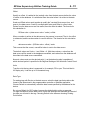
Before You Begin
Minimum Hardware and Software Requirements
The hardware and software you use with RSView Supervisory Edition depends on the
demands your application places on the system. The greater the demand, the more
powerful a system you need. The following are minimum requirements.
For large or complex applications you should use computers with faster CPUs and more
RAM. In any application, faster CPUs and more RAM will result in better performance. In
addition, there should always be sufficient disk space to provide virtual memory that is at
least twice the size of the physical RAM.
RSView SE Server Minimum Platform Requirements:
•
Single RSView SE Server running on the computer (with RSLinx)
o Pentium II or higher, 128 MB RAM or more
o Windows 2000 Professional SP3 or Windows XP Professional SP1 (up to
10 users) or Windows 2000 Server SP3 (more than 10 users)
o Internet Information Server.
•
Multiple RSView SE Servers running on the computer, or any other significant
software application running concurrently:
o Pentium III or higher, 256 MB RAM or more
o Windows 2000 Professional SP3 or Windows XP Professional SP1 (up to
10 users) or Windows 2000 Server SP3 (more than 10 users)
o Internet Information Server.
FactoryTalk Directory Minimum Platform Requirements
• Pentium II or higher, 128 MB RAM or more
• Windows 2000 Professional SP3 or Windows XP Professional SP1 (up to 10
users) or Windows 2000 Server SP3 (more than 10 users)
RSView Studio or RSView Administration Console Minimum Platform Requirements:
• Pentium II or higher, 128 MB RAM or more
• Windows 2000 Professional SP3 or Windows XP Professional SP1 (up to 10
users) or Windows 2000 Server SP3 (more than 10 users)
• Internet Information Server to access sample application SE Servers.
RSView SE Display Client Minimum Platform Requirements:
• Pentium II or higher, 64 MB RAM or more
• Windows 2000 Professional SP3 or Windows XP Professional SP1 (up to 10
users) or Windows 2000 Server SP3 (more than 10 users)
RSView Supervisory Edition Training Guide
2-5
RSView Supervisory Edition System Limits:
•
The tested and recommended maximum number of RSView Studio clients that
can set up an RSView SE application simultaneously is 5.
•
The tested and recommended maximum number of RSView SE servers that can
be used in an RSView SE application is 10.
•
The tested and recommended maximum number of RSView SE servers that can
be hosted on a single computer is 5.
•
The tested and recommended maximum number of RSView SE Clients that can
access an RSView SE application simultaneously is 50.
Using the system beyond these limits is not formally supported.
Domain Controller Requirements
For ease of network and user administration, a domain controller is recommended. All
computers participating in a single application must be members of the same Windows
NT or Windows 2000 domain. The RSView SE Server and FactoryTalk Directory do not
have to be installed on the same computer as the domain controller.
Alternatively, RSView Supervisory Edition can be used in a Windows workgroup
environment. In this case:
•
All computers participating in a single application must be members of the same
Windows workgroup.
•
Create the same set of user accounts and passwords on every computer
participating in an RSView Supervisory Edition application. For details, see Help
provided with Windows.
•
If any computer participating in an RSView Supervisory Edition application is
running Windows XP, disable simple file sharing in Windows XP. For details, see
Help provided with Windows XP.
RSView Supervisory Edition Training Guide
2-6
Activating RSView SE Software
Rockwell Software uses activation files to activate its Windows-based software
packages. The activation files reside on the Activation disk. During installation, the
software prompts you to insert the Activation disk and move the activation key from the
disk to the drive where you’ve installed RSView.
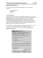
About the Activation disk
RSView comes with an Activation disk (also referred to as a Master disk) that activates
the RSView software. Without activation, RSView runs in demo mode, allowing a
maximum of five HMI servers per application and two hours of use on a local SE Client.
The Activation disk contains:
•
one or more activation keys
The activation key is the software that activates RSView. Depending on what you
purchased, your Activation disk will have one or more activation keys. For example,
if your company purchased four RSView Studio installations, you require four
activation keys. The keys are product-specific. For example, RSView SE Client
requires an SE Client activation key. Multiple copies of the same software require
activation keys with matching serial numbers. All of the activation keys can be on
the same activation disk.
•
•
a program called EVMOVE.EXE that moves activation keys to and from
computers
a program called RESET.EXE that reactivates a damaged activation key
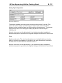
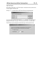
Activation keys
The following table lists the activation keys for RSView Supervisory Edition products:
RSV.STUDIO - RSView Studio (allows a test version of RSView SE Server, a 2-hour test
version of RSView SE Client, RSLinx for RSView, and full use of RSView
Studio, Machine Edition Development and Test Tools)
RSVSESRV.25 - RSView SE Server, 25 displays, and RSLinx for RSView
RSVSESRV.100 - RSView SE Server, 100 displays, and RSLinx for RSView
RSVSESRV.250 - RSView SE Server, 250 displays, and RSLinx for RSView
RSVSESRV.MAX - RSView SE Server, unlimited displays, and RSLinx for RSView
RSVSECLI.RW - RSView SE Client, full function, read/write
RSVSECLI.RO - RSView SE Client, view only
RSVSE.25 - RSView SE Station (for Standalone applications, up to 25 displays)
RSVSE.100 - RSView SE Station (for Standalone applications, up to 100 displays)
RSVSE.250 - RSView SE Station (for Standalone applications, up to 250 displays)
RSVSE.MAX - RSView SE Station (for Standalone applications, unlimited displays)
RSView Supervisory Edition Training Guide
2-7
Installing dedicated or floating licenses
When you install all RSView Supervisory Edition components on the same computer, the
activation keys you install on the computer determine which of the components will run.
To activate your RSView Supervisory Edition software, you can make use of
floating licenses, or dedicated licenses.
Floating licenses
Floating licenses are installed on the computer running the FactoryTalk Directory
software. These licenses ‘float’ to whichever computer needs them. This means that the
license is granted for the exclusive use of any computer while that computer is using the
software. When the software is no longer being used, the license becomes available for
other computers.
For RSView SE Clients, there are two types of floating licenses: read-write licenses, and
view-only licenses. Read-write licenses allow full read-write privileges. View-only
licenses allow read-only privileges.
If an RSView SE Client is set up as read-write, and only view-only licenses are available,
the client will be view-only, and the activation key will override the read-write
configuration of the client.
If an RSView SE Client is set up as view-only, and only read-write licenses are available,
the client will use a read-write license, but the view-only configuration of the client will
override the read-write activation key, and will allow view-only access to the application.
Do not rely on the activation key to determine whether the client is view-only.
Always configure the client explicitly as view-only.
Each floating license requires one installation of the appropriate activation key
on the computer running the FactoryTalk Directory. For RSView Studio, an
RSV.STUDIO key is required for each user. For read-write SE Client licenses, the
RSVSECLI.RW key is required. For view-only SE Client licenses, the RSVSECLI.RO
key is required. To increase the number of licenses available, install additional
activation keys on the FactoryTalk Directory. Keep in mind, however, that no
matter how many licenses you have, you cannot exceed the system limits.
Dedicated licenses
Dedicated licenses are installed on the same computer as the software being used.
These licenses ensure that a particular computer will always have a license to use the
software. Keep in mind, however, that no matter how many licenses you have, you
cannot exceed the system limits.
The software checks for locally-installed, dedicated licenses before requesting a floating
license from the FactoryTalk Directory.
RSView Supervisory Edition Training Guide
2-8
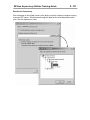
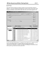
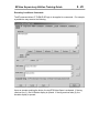
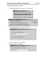
Activating RSView after installation
You might need to reactivate RSView after moving activation keys back to the Activation
disk, or after resetting a damaged key. To reactivate RSView, move the activation key
from the Activation disk back to the hard disk. By default, when you move activation to a
hard disk from the Activation disk, the software moves only one copy (license) of an
activation key.
To move activation keys to the hard disk:
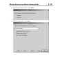
1. In RSView Studio, change the HMI server Startup type to On demand for each
HMI server in each application. To do this:
a. Right-click the HMI server and then click Properties.
b. In the Startup type list, click On demand.
c. Click OK.
2. Close RSView Studio, and all other Rockwell Software products that are using
licenses on this computer.
3. Restart the computer.
4. If RSLinx is installed and running as a service, right-click the RSLinx icon in the
system tray and then click Shutdown RSLinx.
5. Insert the Activation disk into the disk drive.
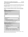
6. Run A:\EVMOVE.EXE where A is the disk drive containing the Activation disk.
The EvMove Summary dialog box opens.
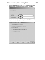
7. In the From list, click the drive containing the Activation disk. In the To list, click
the drive where RSView is installed. Click OK.
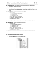
8. Either move activation keys for all installations or for a selected number of
installations:
a.
b.
c.
d.
e.
f.
g.
h.
To move activation keys for all installations, click Move.
To move a selected number of installations, do the following:
Click Edit all.
In the Move box, type 0, and then click OK.
Click the activation key you want to move.
Click Edit Selected.
In the Move box, type the number of activation keys you want to move.
Click OK, and then click Move.
9. To close the EvMove Summary dialog box, click OK.
RSView Supervisory Edition Training Guide
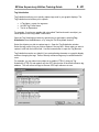
2-9
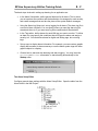
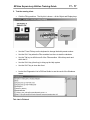
RSLinx for RSView
RSLinx communication software is included on the RSView SE Install CD.
RSView Studio and SE Server provide activation for RSLinx, as long as they are on the
same computer. A separate activation is not needed. RSLinx for RSView may be
installed from the RSView SE Product CD:
RSLinx for RSView will serve data from Rockwell Automation controllers to a distributed
SE application.
RSView Supervisory Edition Training Guide
2 - 10
RSLinx for RSView will use the activation from RSView Studio or RSView SE Server.
If the program starts as RSLinx Lite, it has failed to find any activation.
RSLinx will use an existing activation (RSLinx Professional, OEM, Gateway…) if there is
one on the computer.
RSView Supervisory Edition Training Guide
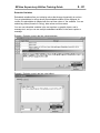
2 - 11
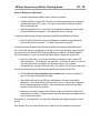
RSLinx for RSView provides your Supervisory Edition project with communication
drivers to connect to Rockwell Automation devices:
In addition, RSLinx for RSView is an OPC Server. It serves data to RSView SE, an OPC
client.
Note: RSLinx for RSView will only act as an OPC Server to RSView Supervisory or
Machine Edition. If you need an OPC Server to other clients, you will need a different
activation of RSLinx.
RSView Supervisory Edition Training Guide
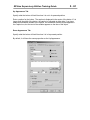
2 - 12
Lab 1 – Working with RSLinx
Objective: Configure RSLinx for RSView to communicate to a SoftLogix 5860 processor.
Explore RSLinx tools.
Software Requirements:
• RSLinx
• SoftLogix 5800 Chassis
• RSLogix 5000
Optional
• ControlLogix processor running the RSView_Class_ControlLogix program
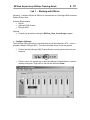
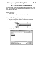
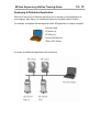
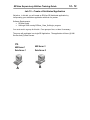
1. Configure SoftLogix
The SoftLogix 5860 processor is a controller that runs in the computer’s CPU. It runs a
program created in RSLogix 5000. This will be the data source for our lab projects.
•
Confirm that the SoftLogix 5800 Chassis Monitor is running as a service on your
computer.
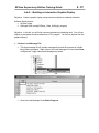
•
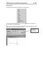
Click the icon in the system tray to open the SoftLogix Chassis Monitor. It has no
modules configured. Right click on the first slot and click Create.
RSView Supervisory Edition Training Guide
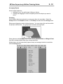
•
Select the L60 SoftLogix 5860 Controller module and click OK.
•
Change the Startup Mode to Last Controller State and click Next.
•
Change the dwell time to 100 ms and click Finish.
2 - 13
RSView Supervisory Edition Training Guide
2 - 14
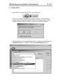
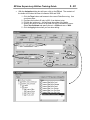
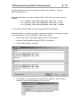
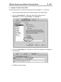
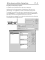
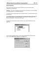
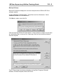
2. Configure RSLinx
•
Open RSLinx by single-clicking its icon in the system tray.
If the icon is not there, RSLinx is not running as a service. If this is the case,
start the service by running the RSLinx Launch Control Panel (Start, Programs,
Rockwell Software, RSLinx). RSLinx 2.3 will run as a service by default.
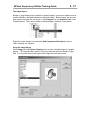
•
SoftLogix 5800 uses the Virtual Backplane driver. Configure it by clicking on the
Configure Drivers icon in RSLinx. Select the Virtual Backplane driver.
RSView Supervisory Edition Training Guide
2 - 15
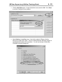
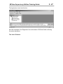
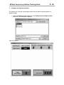
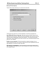
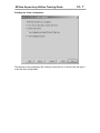
•
Click the Add New button. Accept the default name and click OK. Click Close
to exit the Configure Drivers window.
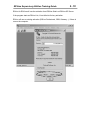
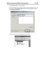
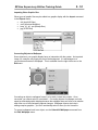
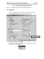
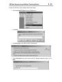
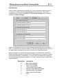
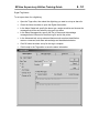
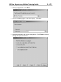
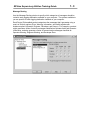
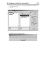
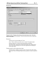
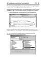
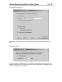
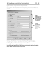
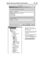
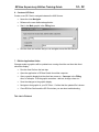
•
Select Options in the View menu. Note that by default, RSLinx will allow
RSLogix to create OPC topics. They are created when the RSLogix program is
saved and downloaded to the processor. You will use the topic in later labs.
Click OK to close the dialog box.
RSView Supervisory Edition Training Guide
2 - 16
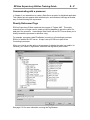
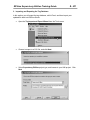
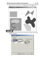
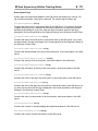
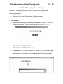
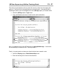
3. Download a program to the processor
•
Open RSLogix 5000 (Start, Programs, Rockwell Software, RSLogix 5000
Enterprise Series).
Open the RSView_Class_SoftLogix.acd file from:
Supervisory Edition Class Files\SoftLogix Program
•
With the program loaded, select Who Active from the Communications menu
•
Select the SoftLogix processor and click Download. Click Download a second
time in the next dialog box.
RSView Supervisory Edition Training Guide
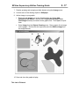
2 - 17
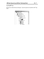
•
The program will be downloaded and in Remote Program Mode. Click the Online
toolbar, and put the program into Run Mode.
•
Close RSLogix 5000
•
Verify the running program in the SoftLogix Chassis and then close it.
RSView Supervisory Edition Training Guide
2 - 18
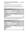
Optional - Configure Communications to a ControlLogix module.
You will use the SoftLogix engine to get data into your project. If the classroom is
equipped with a ControlLogix processor, you may also get data from that.
The controller should be already running the program RSView_Class_ControlLogix
and be available to the student machines via ethernet.
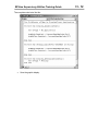
1. Open RSLinx and configure an Ethernet devices driver. You will need to know
the IP address of the 1756-ENET module. Use the Ethernet/IP driver if you are
connecting to a 1756-ENBT module. Confirm the connection in RSWho.
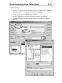
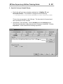
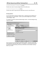
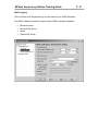
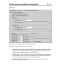
2. Create an RSLinx topic to the ControlLogix processor. (Since you haven’t
downloading the program, one will not have been created automatically).
•
Right-click on the controller in RSWho. Select “Configure New DDE/OPC
Topic”
RSView Supervisory Edition Training Guide
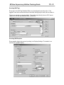
2 - 19
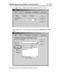
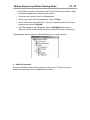
•
The new topic will have the same name as the processor. Click on the Data
Collection tab.
•
Configure the topic to reference an offline logic file: Check the Use Symbols
box. Navigate to the RSView_Class_ControlLogix.acd file.
•
Apply these changes and close the Topic Configuration dialog box.
RSView Supervisory Edition Training Guide
2 - 20
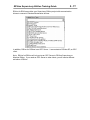
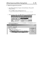
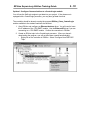
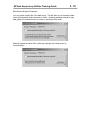
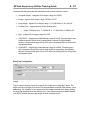
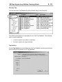
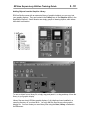
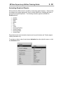
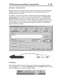
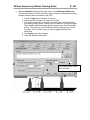
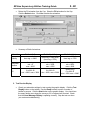
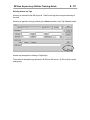
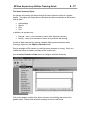
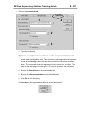
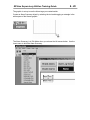
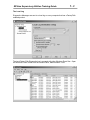
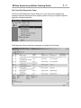
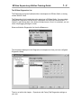
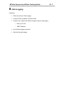
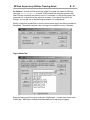
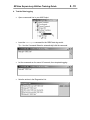
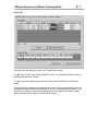
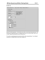
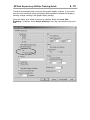
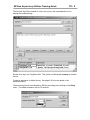
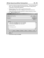
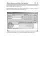
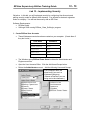
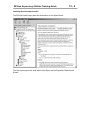
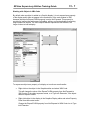
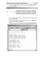
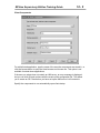
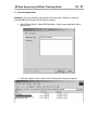
Exploring RSLinx
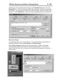
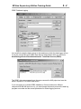
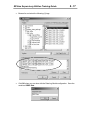
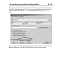
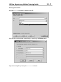
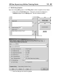
1. Open RSLinx and select Topic Configuration from the DDE/OPC menu. The
topic to the SoftLogix controller was created automatically by RSLogix.
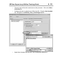
2. Click on the Data Collection tab. Note that the path to the offline RSLogix file
has been automatically added. This allows for offline OPC browsing.
3. Click Done to close the window.
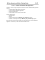
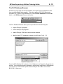
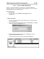
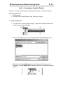
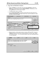
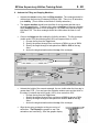
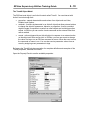
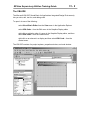
RSView Supervisory Edition Training Guide
2 - 21
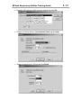
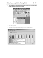
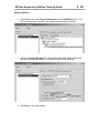
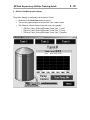
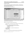
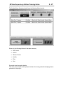
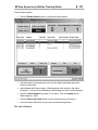
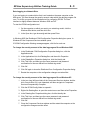
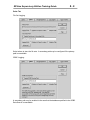
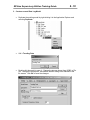
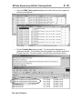
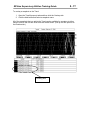
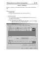
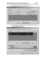
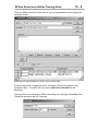
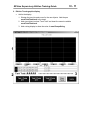
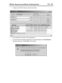
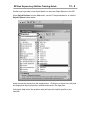
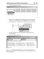
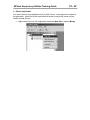
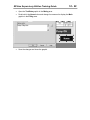
4. Click the RSWho window to bring up a graphical representation of your network.
Expand the driver and find the SoftLogix processor. Right-click on the processor
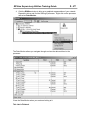
and select Data Monitor.
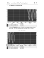
The Data Monitor allows you navigate through and see the data real-time in the
processor.
Close the Data Monitor when you are done looking at it.
This Lab is Finished.
RSView Supervisory Edition Training Guide
This page intentionally left blank.
2 - 22
RSView Supervisory Edition Training Guide
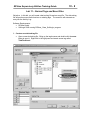
3-1
3. Creating An RSView SE Application
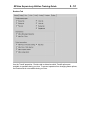
Objectives:
•
Understand the architecture of RSView Supervisory Edition standalone and
distributed applications
•
Install the RSView SE Software components
•
Set the FactoryTalk Directory for the application
•
Create and application with RSView Studio
•
Explore the RSView Studio software interface
•
Configure Areas, HMI Servers and Data Servers
•
Create a Standalone RSView SE Application
RSView Supervisory Edition Training Guide
3-2
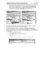
RSView SE - The Distributed Application
RSView Supervisory Edition supports multi-server and multi-client distributed
applications.
RSView SE Client is used to view and interact with the application. The HMI and Data
Server components of the application are separate from the client. There is complete
flexibility in placing servers and clients about the network. The application is configured
with RSView Studio. These software components all reside on the same network.
All users in the distributed application must log into the same Windows Domain or
Workgroup.
RSView Supervisory Edition Training Guide
3-3
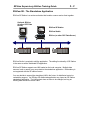
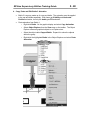
RSView SE - The Standalone Application
RSView SE Station is a runtime activation that bundles a server and a client together.
Optional: RSLinx
(or other OPC Data
Server)
RSView SE Station
RSView Studio
RSLinx (or other OPC Data Server)
RSView Studio is required to edit the application. The editing functionality of SE Station
is the same as with a distributed SE application.
RSView SE Station supports one HMI loaded on the local computer. Multiple data
sources, local or remote, may serve data to the standalone application. Redundancy is
not supported with the SE station license.
You may decide to expand the standalone HMI in the future, for distributed control or
redundancy support. An RSView SE distributed application may import an SE Station
standalone application. The HMI project does not have to be changed, as long as
existing data references remain valid.
RSView Supervisory Edition Training Guide
3-4
Creating an Application
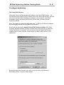
The FactoryTalk Directory
Information about a distributed application resides in the FactoryTalk Directory. You
must decide which computer on your network will be the FactoryTalk Directory, and then
you must install the FactoryTalk Directory software on that computer. You will be
prompted to specify the FactoryTalk Directory Server when you install RSView
Supervisory Edition.
Note: This applies to a distributed application only. An RSView SE Station installation
will automatically reference a local FactoryTalk Directory.
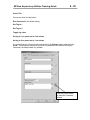
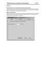
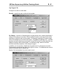
At any time you may use the Specify FactoryTalk Directory Location utility (Start,
Programs, Rockwell Software, Utilities) to set the name of the computer on which the
FactoryTalk Directory is installed. You must use the Specify FactoryTalk Directory
Location utility on every computer on the network you want to have access to your
applications.
Browse and select the computer you wish to use as the FactoryTalk Directory.
Redundancy will be covered in a later chapter.
RSView Supervisory Edition Training Guide
3-5
The FactoryTalk Directory holds application files. These files have an .rnad extension,
and contain the high-level information of an application - user security information and
the location of the HMI and Data servers.
The application files are held in this path:
C:\Documents and Settings\All Users\Application Data\Rockwell\RNAServer\
SE Distributed application files are in the \Global folder. SE Standalone and Machine
Edition application files are in the \Local folder.
Client computers (those running SE Clients and RSView Studio) contain a locally cached
copy of the application:
C:\Documents and Settings\All Users\Application Data\Rockwell\RNAClient
RSView Supervisory Edition Training Guide
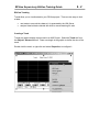
3-6
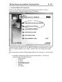
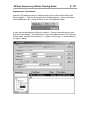
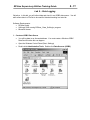
Open RSView Studio
An application is created in RSView Studio. Open the program (Start, Programs,
RSView Studio). You must decide the scope of your project you will ultimately run.
When you purchase RSView Supervisory Edition, you may also create SE Standalone or
Machine Edition projects. RSView Machine Edition is outside the scope of this course.
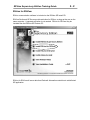
Create a new application from the next dialog box.
RSView Supervisory Edition Training Guide
3-7
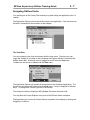
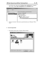
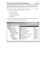
Navigating RSView Studio
You (and anyone on the FactoryTalk network) may start editing the application after it is
created.
The Application Explorer window shows the name of the application. User Accounts and
Secured Commands will be covered in a later chapter.
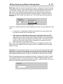
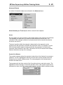
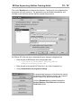
The View Menu
You can customize your work environment with the view menu. From here you can
toggle the visibility of a number of items including the Explorer Window, the Activity Bar
and the Status Bar. Workbook mode is toggled on and off from the View menu.
Toolbars are also shown or hidden with the View menu.
The Application Explorer will contain all the elements of the distributed application. The
window can be shown and hidden from the View menu. It may be displayed in different
ways. To change how it looks, right click in the title bar.
The choices are docked, floating or MDI (Multiple Document Interface) child.
You may dock the Project Explorer to any side of the RSView Studio workspace.
Floating allows you to move the Project Explorer anywhere in the display by clicking and
dragging in its title bar.
3-8
RSView Supervisory Edition Training Guide
With either of these options the Project Explorer remains on top of all windows. To force
it to act as any other window, select MDI Child. It is now listed in the Windows menu
item and can be minimized, maximized and given focus like any other open window.
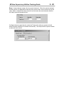
The Status Bar
The Status Bar gives general information on the active window or object selected. In the
example below, the position, size and name of an object is displayed.
Graphics
Toolbar
Status Bar
Diagnostics List
RSView Supervisory Edition Training Guide
3-9
Workbook Mode
Selecting Workbook Mode in the View menu displays tabs at the bottom for each
graphic display and/or editor that you have opened from the Project Explorer. This can
speed up the navigation of many open windows – just click on the tab to bring the
corresponding window to the front.
Building a Distributed Application
Your distributed application may organized into distinct Areas, containing HMI Servers
and Data Servers.
Areas
Areas allow you to divide an application into manageably-sized, logical parts, or to
organize the application in a way that makes sense for the process you are controlling.
Areas do not apply to standalone applications.
An area might represent a portion or stage of a process, or a region within the process
facility. For example, an automotive plant might be divided into areas called Press and
Fabrication, Body Shop, Paint Shop, Engine and Transmission. A bakery might be
divided into areas called Ingredients, Mixing, Baking, and Packaging.
Alternatively, a plant with identical production lines might be divided into areas called
Line 1, Line 2, Line 3, and so on. This Preface would allow you to add new, identical
production lines to the application by copying HMI server projects into new areas.
Each area can contain one or more sub-areas, and one or more data servers. Each area
or sub-area can contain only one HMI server. Right-click on the root project and select
New Area… to create an Area.
Application
Root Area
RSView Supervisory Edition Training Guide
3 - 10
All applications have one system-defined area called the application root area. The
application root area has the same name as the application, and contains the User
Accounts and Secured Commands lists. You can use the application root area like any
other area, for example to contain an HMI server, or one or more data servers.
The home area is the area in which an application component is located. When you
refer to an application component, but don’t specify the area in which the component is
located, RSView uses the home area to locate the component.
For example, if two graphic displays are located in different areas, each has a different
home area.
In this example, the graphic display called Ingredients is in an area called Mixing. The
graphic display’s home area is Mixing. The graphic display called Laminating is in an
area called Packaging. The graphic display’s home area is Packaging.
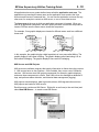
HMI Servers and HMI Projects
HMI servers are software programs that supply information to clients when they request
it. HMI servers have no user interface. Once installed, they run as a set of Windows
services. HMI servers store HMI project components (for example, graphic displays),
and serve these components to clients. Each HMI server also manages a database of
tags, and performs alarm detection, and historical data management (logging).
HMI projects contain displays, data log models, alarms, HMI tags and other services.
HMI projects are loaded on HMI servers.
Each Area may contain one HMI Server. Right-click on an Area (or the root Area) and
select New HMI Server… to create a new HMI Server.
RSView Supervisory Edition Training Guide
3 - 11
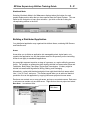
Creating an HMI Project
There are three options for including an HMI Project in the newly created HMI Server.
1. Create a new HMI project
2. Copy an existing HMI project from another SE server.
3. Import an existing RSView32, RSView SE or RSView ME HMI project.
4. Reference, but not copy, an existing SE HMI project.
When you create a new HMI project you give it a name and specify the computer that it
will reside on.
RSView Supervisory Edition Training Guide
3 - 12
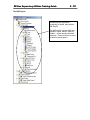
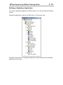
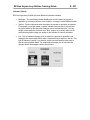
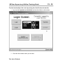
The HMI Project
A distributed SE application
containing (4) Areas, each with an
HMI Server.
The HMI project contains HMI tags,
graphics, trends, alarms, data log
models – all the operator interface
elements. These will all be covered
in detail in later chapters.
RSView Supervisory Edition Training Guide
3 - 13
Creating an HMI Project will create many files and folders on the hard drive of the
computer that you specified to be the HMI Server.
All HMI Projects are collected in the directory:
C:\Documents and Settings\All Users\Documents\RSView
Enterprise\SE\HMI Projects
If you are developing an application on a computer and wish to deploy it on a different
computer, you must change the HMI Server location.
Before you change the computer that will act as the HMI Server, you must first move
these HMI Project files to the new computer. Then specify the new computer in the HMI
Server properties (see next page).
3 - 14
RSView Supervisory Edition Training Guide
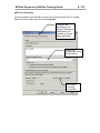
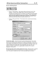
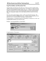
HMI Server Properties
Certain properties of an HMI Server can be viewed and changed after it’s created.
Right-click on the HMI Server and select Properties.
Configure HMI
Redundancy and
Startup Components
(Redundancy not
available in a Stand
alone application)
Change the
computer that hosts
the HMI Server
HMI Server
Licensing
Information
RSView Supervisory Edition Training Guide
3 - 15
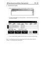
Building a Standalone Application
You create a standalone application in RSView Studio to run with an RSView SE Station
license.
Standalone applications consist of one HMI Server. No Areas are used.
The HMI Project created in a standalone application may be imported into a distributed
application at a later time.
RSView Supervisory Edition Training Guide
3 - 16
Communicating with a processor
There are two basic ways of establishing communications with a processor.
1. Data Servers – Create a Data Server in an Area (or at the root) of your SE
application. Associate the data server with a local or remote OPC server. A data
server provides client computers with data such as:
•
programmable controller values
•
OPC tags, and their value or status information
•
named variables in a ControlLogix processor
Data servers enable the direct referencing of processor data without using a
static tag database. This is a more efficient way of getting data to a client - data
does not go through the HMI server at all.
2. HMI Tags – Use the communication editors within an HMI Project to configure
communications with a processor. Create HMI tags in the Tag Database Editor
to reference data in a PLC. It is necessary to create HMI tags to implement
alarming and security. This method will be covered in chapter 4.
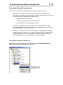
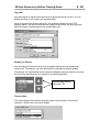
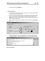
Creating and configuring a Data Server
Right-click on an Area (or the root of the application) and select New Data Server.
Multiple data servers may be assigned to an Area.
RSView Supervisory Edition Training Guide
3 - 17
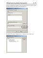
Configure the data server properties. Specify the computer that will run the OPC server.
Associate the server with an OPC Server by browsing for it:
All installed OPC servers will populate the list. Choose the one you want to use.
RSView Supervisory Edition Training Guide
3 - 18
Data Server Redundancy
One advantage to using Data Servers is the ability to specify a backup computer running
a second OPC server. All references through the data server will automatically switch
over if the first data server is lost.
RSView Supervisory Edition Training Guide
3 - 19
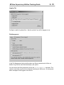
Data Server Advanced Properties
You may create a cache file of the data server. This will allow you to browse the data
server tag information when the server is offline. Including extended information (tag
data types) will increase the time to create or synchronize the cache.
Manually update the cache file to reflect any changes in the data server by
synchronizing it.
RSView Supervisory Edition Training Guide
3 - 20
Lab 2 – Create a Standalone SE Application
Objective: Work in a single computer environment to create a standalone SE application.
You will:
• Install the RSView SE Software components
• Create a new SE standalone application
• Explore the HMI Project
• Create a data server to access controller data.
Software Requirements:
• RSView Studio
• RSLinx
• SoftLogix 5860 running the RSView_Class_SoftLogix program
• Optional - ControlLogix running the RSView_Class_ControlLogix program
Note: Later in the course you will combine your work with others to create a distributed
application. At that time you will create Areas and HMI Servers.
RSView Supervisory Edition Training Guide
3 - 21
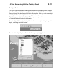
1. Install the RSView SE components
There are many different components of RSView Supervisory Edition. Run the
setup.exe program (\Software Installs\RSView SE directory)
The first two items, RSView for SE, and RSLinx for RSView, are necessary for our labs.
RSLinx is already installed on your system - check to see if it is running in the system
tray.
RSLinx Enterprise is used for RSView Machine Edition only in release 3.0. Do not install
it.
•
Install RSView Supervisory Edition with the default options. This will do a
complete install of all SE components:
o RSView Studio
o SE Server
o SE Client
o Administration Console
o FactoryTalk Directory
o Samples
o RSI Utilities
RSView Supervisory Edition Training Guide
3 - 22
2. RSLinx and SoftLogix
•
Confirm that the program from Lab1 is running in the SoftLogix processor. Click
on the SoftLogix icon in the system tray of your computer:
•
The SoftLogix Chassis Monitor window is opened. Bring up the tooltip
information by hovering the mouse over the processor:
RSView Supervisory Edition Training Guide
3 - 23
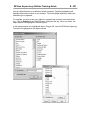
•
Open RSLinx and confirm that the RSView_Class_SoftLogix topic (created in
Lab 1) exists. Select Topic Configuration from the DDE/OPC menu.
•
Notify your instructor if there are any questions about your SoftLogix / RSLinx
setup.
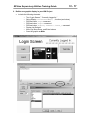
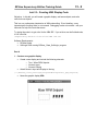
3. Create the Application
•
Open RSView Studio (Start, Programs, RSView Studio).
RSView Supervisory Edition Training Guide
3 - 24
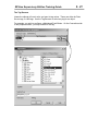
•
Select SE Stand-alone and click Continue.
•
Give the application a name. Make it unique, so you can identify it later on. Use
your name, ex: Jim Standalone App. For this manual, the application will be
named Rootbeer Standalone.
The basic structure of the standalone application is created:
RSView Supervisory Edition Training Guide
3 - 25
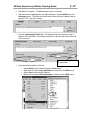
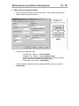
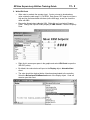
4. Create a Data Server
Create a Data Server within the application to reference the RSLinx OPC Server. This is
how the SoftLogix (or ControlLogix) tags will be directly referenced.
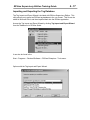
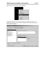
•
Right-click on the root of the application and select New Data Server, OPC Data
Server.
RSView Supervisory Edition Training Guide
3 - 26
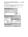
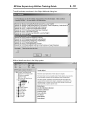
•
Keep the computer setting to your local computer. Browse for the RSLinx
Remote OPC Server. (The remote part will come when you combine
•
Click OK to close the Data Server configuration.
RSView Supervisory Edition Training Guide
3 - 27
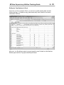
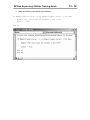
The Application should look like this:
Note the messages in the Diagnostics List at the bottom of RSView Studio confirming
the active data server.
This Lab is Finished.
RSView Supervisory Edition Training Guide
This page intentionally left blank.
3 - 28
RSView Supervisory Edition Training Guide
4-1
4. Communications
Objectives:
•
Understand the difference between communicating to a processor by directly
referencing a Data Server and by using HMI tags
•
Understand when HMI tags are required
•
Build an HMI Tag Database
RSView Supervisory Edition Training Guide
4-2
Communicating with a processor
In Chapter 3 you learned how to create a Data Server as part of a distributed application.
This chapter gets into greater detail with that topic, and introduces HMI tags as another
way of communicating with a processor.
Directly Referenced Tags
RSView Supervisory Edition introduces the concept of “Tagless HMI”. This simply
means that you no longer need to create an HMI tag database to get at the value of a
data point in a processor. Associating a Data Server with an OPC Server allows you to
directly browse the processor to reference a tag.
For example, a program called FilterStation is running in a ControlLogix processor.
RSLinx is used as the OPC server. A topic is set up in RSLinx to point to the
ControlLogix processor.
When you need to use the value in the processor (to display the value in a graphic, for
instance), you initiate a Tag Browser, and select the tag directly while online.
See page 5-21 for more information on using the Tag Browser.
RSView Supervisory Edition Training Guide
4-3
Directly referencing the processor tag values requires an OPC server. RSView
conforms to the OPC Data Access (DA) 2.0 specification for information exchange
among automation or control applications, field systems or devices, and business or
office applications.
RSView provides direct access to the basic set of attributes of all OPC-DA-compliant
tags. The OPC-DA specification calls these tags ‘data items’. In RSView, you access
OPC-DA-compliant tags through the data server. The tags you access through a data
server are called data server tags.
Using Directly Referenced Tags
Use directly referenced data server tags whenever you need to access a value from the
controller, and you don’t need to attach alarming or security, or need to manipulate the
value of the tag.
Using data server tags allows you to add, modify, or delete tags in a device without
having to duplicate the changes in RSView’s HMI tag database. It allows you to browse
a tag in a controller as opposed to creating a static database.
Data server tags allow access to complex data types. Some devices, for example
ControlLogix processors, support complex data types such as arrays and structures.
Your controller might have structures that contain hundreds of member elements.
Referencing tag values directly eliminates the need for creating one HMI tag for each
member and creating additional HMI tags every time you create a new instance of a data
structure in your controller
RSView Supervisory Edition Training Guide
4-4
An additional benefit of directly referencing tags is the efficiency achieved in bypassing
the HMI server. The OPC server serves its data to the client. The HMI does not have to
process the information. This resolves to less network hops in a distributed environment.
In the diagram below, tag information from the ControlLogix is served directly from the
OPC Server (RSLinx) to the Client requesting the information. It is not routed through
the HMI Server.
SE Client
Data Server
(RSLinx)
HMI
Server
RSView Supervisory Edition Training Guide
4-5
HMI Tags
In addition to directly referenced data server tags, RSView provides a tag with additional
properties for alarms, security, and data manipulation. This type of tag is called an HMI
tag. Every HMI Project has its own Tag Database to store these HMI tags.
RSView Supervisory Edition Training Guide
4-6
When to use HMI Tags
You must use HMI tags (that is, you cannot use data server tags) for any of the following
things you might need to do in your application.
Alarms An alarm occurs when something goes wrong. It can signal that a device or
process has ceased operating within acceptable, predefined limits or it can indicate
breakdown, wear, or a process malfunction. In RSView, HMI tags provide the only
method for triggering an alarm when a tag has a certain value.
Security You can assign a security code only to an HMI tag. To prevent users from
changing a value in a device, create an HMI tag for the device’s address, and then
assign security to the tag
Data manipulation You must use HMI tags if the data server you are using does not
provide for scaling or offsetting a value, or setting minimum or maximum limits on a
value.
Scale and offset The scale and offset modify the ‘raw data’ that comes from
and goes to the programmable controller before it is saved in the computer’s
memory (called the value table). The scale and offset also modify the value
specified in RSView before it is written to the programmable controller. The scale
is a multiplication factor—the value from the PLC is multiplied by the scale. The
offset is a fixed value—after the value from the PLC is multiplied by the scale, the
offset amount is added.
Minimum and maximum HMI Tags allow you to set minimum and maximum
values that can be written to the programmable controller or server. These values
do not affect what is read from the programmable controller or server. For
example, if you specify a minimum of 0 and a maximum of 100, RSView would
be able to read a value of 200 from a PLC and store it in the value table, but
would not be able to write this value to the PLC.
Storing values in RSView’s memory A memory tag can be used to store values
without the need for an attached or accessible device. For example, you might need to
store a value in memory to store result of a calculation, or to temporarily keep a value for example, a counter or index number. Values can be calculated and held in memory
with Derived Tags.
RSView Supervisory Edition Training Guide
4-7
Creating HMI Tags
HMI tags are created within an HMI project. Open the project and expand the HMI Tags
folder.
RSView Supervisory Edition Training Guide
4-8
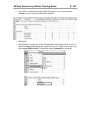
The Tag Database Editor
Tags may be created once a node exists. Open the Tag Database Editor by double
clicking the Tags icon in the HMI Tags folder:
Tag Types
Tag type specifies how the application interprets data from the programmable controller,
or other source, and how it is represented in the application. Data source specifies
where the data for a tag will come from. There are three tag types:
•
Analog tags store a numeric value from a range of values defined for the tag.
Use them to represent devices that can have a range of values such as
temperature, pressure, flow, or the position of a rotary control.
•
Digital tags store a numeric value of either 0 or 1. Use them to represent devices
such as switches, contacts and relays that have two states: on or off.
•
String tags store ASCII strings that can be a string of characters or whole words.
The maximum size string allowed is 82 characters.
Tag Data Sources
•
Device – A tag that gets its value from an external data source. The data can
come from a programmable controller or other device via RSLinx or other OPC
server.
Note: See Appendix C of the RSView SE Users Guide for information on using
DDE communications with HMI tags.
•
Memory – A tag whose value is stored only in the RSView Machine Edition value
table. It does not reference any physical device.
Note: Memory tags may be designated as Retentive. Their value will remain
after an RSView SE Client has shut down.
•
System – A folder of system tags are created automatically with a new project.
These are specialized memory tags that hold system information.
RSView Supervisory Edition Training Guide
4-9
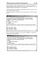
System Tags
The system folder and tags are created by default, and cannot be edited, deleted or
added to. They store information generated by the system such as recent alarm values,
current time and date, communication status and errors, and currently logged-in user.
You can use system tags wherever you would use any other tag. For example, you can
create a string display object in a graphic display and assign the system tag
“system\Time” to the object. At runtime, the object would display the information stored
in the system tag, which is the current system time.
RSView Supervisory Edition Training Guide
4 - 10
Organizing the Tag Database
Open the Tag Database editor by double-clicking its icon in the System folder of the
Project Explorer. Tags may be organized into a folder hierarchy. Create new folders
from the Edit menu, or by using the button on the Tag Database toolbar.
A tag’s name incorporates the folder(s) it resides in. Once a name and type are given,
they cannot be changed. Tag names may be up to 255 characters long. The name can
include letters, numbers, the underscore (_), hyphen or minus sign (-), and backslash (\)
(for tags in folders).
RSView Supervisory Edition Training Guide
4 - 11
Entire folders and their contents may be duplicated. This greatly speeds up the
development of a project where several similar tag groups are involved.
Creating New HMI Tags
Entering Tags Manually
Create new tags by filling out the form view of the tag database. Fields are available
based on the tag type chosen. Once you start editing a tag, the Accept and Discard
buttons are available on the right side of the form. One of these buttons must be
selected before moving on to another tag. Accepting a tag edit enters the information
into the spreadsheet view of the tag database.
Digital Tag Configuration:
RSView Supervisory Edition Training Guide
4 - 12
Analog Tag Configuration:
Minimum/Maximum
These boxes establish the minimum and maximum possible values for the tag. They
ensure that values outside a specified range will not be written to the data source.
However, values outside the range can still be read from the data source. The minimum
and maximum values for a floating point analog tag cannot exceed the range +/3.40282e +38.
Numeric values must use the decimal point (.) as the decimal symbol, regardless of
which decimal symbol is specified in the Regional Settings of the Windows Control Panel.
Scale
Specify a scale value. The value from the data source is multiplied by the scale value
before it is written to the database. It is divided by the scale value before it is written to
the data source. A scale value of 0 will result in an error.
Numeric values must use the decimal point (.) as the decimal symbol, regardless of
which decimal symbol is specified in the Regional Settings of the Windows Control Panel.
RSView Supervisory Edition Training Guide
4 - 13
Offset
Specify an offset. It is added to the (scaled) value from the data source before the value
is written to the database. It is subtracted from the value before it is written to the data
source.
Scale and Offset values work together to modify the "raw data" that comes from, and
goes to, the data source. Scale is a multiplication factor and Offset is a fixed value.
Values from the data source are first scaled, then the offset is added. The formula for
this calculation is:
RSView value = (data source value * scale) + offset
When a number is written to the data source, the process is reversed. That is, the offset
is subtracted, and the scale number is used for division. The formula for this calculation
is:
data source value = (RSView value - offset) / scale
This ensures that the correct, unmodified value is sent to the data source.
The default values are Scale = 1 and Offset = 0. With these values, a value from the
data source will be saved in the database unmodified, and values from the database will
be written to the data source unmodified.
Numeric values must use the decimal point (.) as the decimal symbol, regardless of
which decimal symbol is specified in the Regional Settings of the Windows Control Panel.
Units
Type the units the tag value is measured in, for example, PSI or rpm. This text label is
for display only. It can be up to 20 characters long.
Data Type
For analog tags with Device as the data source, select the data type that matches the
format of the data stored in the programmable controller or Windows application.
Choose Default to automatically match the data format specified by the address for the
device.
Do not use Default for OPC nodes, because the default might not be as expected.
For tags with Memory as the data source, select the data type that matches the format of
the data you will store in the tag. Choosing Default is the same as choosing Floating
Point format.
RSView Supervisory Edition Training Guide
4 - 14
These are the data types and their allowable minimum and maximum values:
•
Unsigned Integer - unsigned 16 bit integer; range 0 to 65535
•
Integer - signed 16 bit integer; range -32768 to 32767
•
Long Integer - signed 32 bit integer; range -2,147,483,648 to 2,147,483,647
•
Floating Point - single-precision (32-bit) floating point;
o
range -3.40282e+38 to -1.17549e-38, 0, 1.17549e-38 to 3.40282e+38
•
Byte - unsigned 8 bit integer; range 0 to 255
•
3-Digit BCD - 3-digit binary-coded decimal; range 0 to 999. This data type is only
supported with the Direct driver node definition reserved for Allen-Bradley
devices. Using this data type with an OPC server (including RSLinx) will produce
unexpected results.
•
4-Digit BCD - 4-digit binary-coded decimal; range 0 to 9999. This data type is
only supported with the Direct driver node definition reserved for Allen-Bradley
devices. Using this data type with an OPC server (including RSLinx) will produce
unexpected results.
String Tag Configuration
Length
Type a number between 1 and 82 to specify the length of the string tag in bytes. The
length must be a multiple of the size of the programmable controller data element you're
addressing. For example, if you reference two-byte data elements in an integer section,
the string tag length must be a multiple of two. If you reference one-byte data elements
in an ASCII section, the string tag length must be a multiple of one.
RSView Supervisory Edition Training Guide
4 - 15
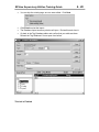
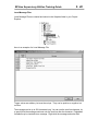
The PLC Database Browser
Another way to get tags into the Tag Database is to import Symbol and Address data
from an existing ladder logic program. This option applies to PLC/SLC/MicroLogix
programs only. With the Tag Database open, choose Other Databases from the Edit
menu, or the DB Browser button on the toolbar:
The PLC Database Browser allows you to import data from the following files:
•
.rsp for RSLogix 5 programs
•
.rss for RSLogix 500 programs
•
.ctd for RSLogix 5/500 saved as an external database.
•
.dsc for legacy PLC databases (created using WinLogic 5 or A. I. 5)
Once the PLC Database file is chosen, a list of Addresses and Symbols will populate the
window. This list may be sorted by address or symbol name, and filtered. Wildcards are
not used and you cannot filter beyond a slash. Example: filter of B3/1 will not show
B3/10, B3/11, and so on.
RSView Supervisory Edition Training Guide
4 - 16
Select the address and symbol sets you wish to import by clicking and dragging in the
window. They will be added to the folder that was open when you initiated the PLC
Database Browser. You may specify a different folder, or create a new folder, in the
“Import Tags into Folder:” field.
Specify an OPC topic that the tags will use.
The Symbol name will become the RSView HMI tag name. If there is no symbol, the
address will become the tag name. You have the option to use symbol names as the
tag address.
If you import a tag name that already exists, you will be prompted with the following
dialog box:
RSView Supervisory Edition Training Guide
4 - 17
Importing and Exporting the Tag Database
The Tag Import and Export Wizard is included with RSView Supervisory Edition. This
utility allows you to export an RSView tag database to the .csv format. This file can be
edited in Microsoft Excel, and then imported back into the RSView application.
Access the Tag Import and Export Wizard by clicking Tag Import and Export Wizard
from the Tools menu in RSView Studio.
It can also be found in the
Start – Programs – Rockwell Software – RSView Enterprise – Tools menu
Options with the Tag Import and Export Wizard:
RSView Supervisory Edition Training Guide
4 - 18
Editing the Tag Database in Excel
Once the .csv file is opened in Excel, you are free to modify existing data and add
folders and tags. It is safest to copy, paste and modify rows of data so no column
information is left out.
After your .csv file edits are saved, you can import the new file back into the Machine
Edition project with the Tag Import and Export Wizard.
RSView Supervisory Edition Training Guide
4 - 19
Querying Tags
You can search the Tag Database by typing a search string in the Query Box:
The results are displayed in the spreadsheet view of the Tag Database. Two wildcards
may be used for searching:
•
* is used to replace any number of characters
•
? is used to replace any single character
Tag Statistics
Choose Tag Statistics from the View menu (the Tag Database must be open and have
focus) to bring up a summary of your Tag Database.
RSView Supervisory Edition Training Guide
4 - 20
Lab 3 – Create an HMI Tag Database
Objective: Create a tag database in your HMI project. Populate the database by
entering tags manually. Use OPC Browse to select tag addresses. Use the Tag Import
and Export Wizard to edit the database in Excel.
Software Requirements:
• RSView Studio
• SoftLogix 5860 running the RSView_Class_SoftLogix program
• Microsoft Excel
1. Manual Tag Creation
•
Open the Tag Database editor by double-clicking its icon in the HMI Tags folder
in the Project Explorer.
•
Create a new folder for tags called “mem” by selecting New Folder from the Edit
menu, or by clicking the Create Folder button.
•
Manually create three tags in the “mem” folder. Use Memory as the Data
Source, and keep all the default values.
•
Configure the tags to hold their value by designating them Retentive.
RSView Supervisory Edition Training Guide
4 - 21
2. HMI Device Tag
•
The timer accumulator in the SoftLogix program is in milliseconds. Create a new
HMI tag to scale it. First create a new folder called Scaling.
•
Create a device tag named Timer within the folder.
•
Use the Tag Browser to specify the timer accumulator in the SoftLogix.
•
The timer accumulator is in milliseconds. Scale it so the end result will be in
seconds.
RSView Supervisory Edition Training Guide
4 - 22
3. Importing and Exporting the Tag Database
In this section you will export the tag database, edit in Excel, and then import your
updated file back into RSView Studio.
•
Open the Tag Import and Export Wizard from the Tools menu.
•
Choose to export to a CSV file, and click Next
•
Select Supervisory Edition project type, and browse to your HMI project. Click
Next
RSView Supervisory Edition Training Guide
4 - 23
•
Create only the Tags file. Note the path. Click Finish to create the CSV file.
•
Open the Tags CSV file. You can either double click on the file in Windows
Explorer, or start Excel and open the file. (Make sure and change the file type
that Excel will look for)
RSView Supervisory Edition Training Guide
4 - 24
•
The CSV file contains the tag and folder information. Look over the column
headings in row 1 to see the information included.
•
Edit the file.
•
Add a folder by copying one of the existing folder entries (right-click on row 5 or 6
and select Copy) and inserting the copied row into row 7 (right click on row 7 and
select Insert Copied Cells). Rename the folder Comments (in column B).
RSView Supervisory Edition Training Guide
4 - 25
•
Create a new string tag in Excel. Copy the row containing the mem\string tag
(row 12). Insert the copied cells into row 14. Rename the tag
Comments\Repair1.
•
Save the changes to the .csv file. Answer Yes to overwrite the existing file and
to keep the workbook in the .csv format. Close Microsoft Excel.
•
Import your edited CSV file into your RSView project. Open the Tag Import and
Export Wizard again. Choose Import RSView tag CSV files. Click Next.
•
Select your HMI project. Click Next.
•
Select your CSV file to import. Click Next.
RSView Supervisory Edition Training Guide
4 - 26
•
You can skip the existing tags, as none were edited. Click Next.
•
Click Finish to start the import.
•
The Database Import summary window will open. Review this and close it.
•
Go back to the Tag Database editor and confirm that your edits are there.
Refresh the Tag Database if it was open from before.
This Lab is Finished
RSView Supervisory Edition Training Guide
5-1
5. Graphic Displays
Objectives:
•
Use the HMI Project Graphic Display editor to create and modify RSView
Supervisory Edition graphic displays
•
Configure Display Settings for graphic displays
•
Use the Library to add pre-configured graphics to a display
•
Learn the different Objects available for use on graphics, including
o
Drawing Objects
o
Indicators
o
Display Navigation
o
Push buttons
o
Gauges, Graphs, Trends
o
Control List Selector
o
Keys
o
Local Message Displays
o
Recipe
o
Active X controls
o
Imported graphics
•
Group, Align, and Arrange Objects
•
Use Key Assignments for interactive objects
•
Use the Object Explorer and Property Panel
•
Apply Animation to Objects, copy and paste Animation between Objects
•
Use Tag Placeholders and Parameter Files with graphic displays
•
Create Local Message Files for use in graphic displays
•
Use Test Run to evaluate and troubleshoot a graphic display
•
Use Display Navigation to link graphic displays together
RSView Supervisory Edition Training Guide
5-2
The Graphic Display Editor
RSView Machine Edition graphics are created and modified by opening the Graphics
folder in the Project Explorer.
The Displays editor holds all graphic displays in the project.
The Libraries editor contains many pre-built graphics that can be easily added to your
project’s graphic displays.
The Images editor holds bitmap images used in the project’s graphic displays.
The Parameters editor holds Parameter Files for use with graphic displays containing
Tag Placeholders.
The Recipes editor holds recipe text files used to load saved values into numeric and
string inputs.
The Local Messages editor holds Local Message files for use with graphic displays
containing a Local Message Display object.
The Trend Templates editor holds trending .tem files used to save trend configurations.
The Trend Snapshots hold .dbf files of trending data that has been saved. These files
may be overlaid on a trend object.
RSView Supervisory Edition Training Guide
5-3
Creating a New Graphic Display
A graphic display represents the operator’s view of plant activity. The display can show
system or process data and provide operators with a way to write values to an external
device such as a programmable controller. Operators can also print the display at run
time to create a visual record of tag values.
There are multiple ways to create a new display.
A New Display button is part of the Standard toolbar:
Right-click the Display icon in the Graphics folder in the Application Explorer:
Select Display from the New command under the File menu:
Drag and drop the Display icon in the Graphics folder into the right pane:
RSView Supervisory Edition Training Guide
5-4
Customizing Your Environment
Many toolbars are available when using the Graphics Editor. Choose to show or hide
these from the View menu.
It may be helpful to display toolbars while editing a graphic display. Any of the toolbars
may be floated in your editing area, or docked in the window.
RSView Supervisory Edition Training Guide
5-5
Display Settings
Display Settings determine how the graphic display will look and act during runtime.
Open the Display Settings Editor from the Edit menu, or by right-clicking in an open area
(not on an object) of the graphic display.
RSView Supervisory Edition Training Guide
5-6
Properties Tab
Displays can be one of three different types:
•
Replace - Choose Replace to have this display replace any display of any type
on the screen at run time, if this display overlaps the other by at least one pixel.
•
Overlay - Choose Overlay to position this display over any others on the screen.
•
On Top - Choose On Top to position the display in front of any other display (of
overlay or replace types) that might be open at run time.
Tip: At run time use the PullForward, PushBack, and SetFocus commands to cycle
through multiple On Top and Overlay screens.
You can fix the size and position of the graphic here, or leave at “Use Current Size” .
Use the Cache After Displaying settings to affect the graphic performance.
Choose No if you don’t want graphic displays loaded into the display cache when
they are displayed for the first time. This saves memory at the expense of
performance. To remove displays from the cache use the FlushCache command.
Choose Yes to load a graphic display into the display cache when it is displayed
for the first time. This makes subsequent displays of the graphic faster because it
does not have to be read from disk.
Each display in the display cache uses memory. Once Windows consumes all
physical memory, it is forced to swap to disk. This results in all system activities
slowing down.
To conserve system resources, you should limit the total number of displays in
the cache to 40. This includes displays loaded using this option or using the
Display /Z or /ZA command. You should also limit the number of screens that are
displayed or minimized simultaneously to 40.
Always Updating
Check this box to keep the cached display up-to-date. For example, choose this
option to continuously update trend data for the display, even when the display is
not visible. This option also makes subsequent displays even faster.
Always updating a cached display can cause added communications overhead
because data will be retrieved for tags whose values wouldn't otherwise be
needed.
If you use the Always Updating option with the Cache After Displaying option
(Display /ZA), the startup command is executed when the display is loaded into
the cache. The shutdown command is executed only when the cache is flushed
(using the FlushCache command).
RSView Supervisory Edition Training Guide
5-7
The tag update rate may be limited by the display settings.
Select an item from the Maximum Tag Update Rate drop-down list to specify the
maximum rate at which tags in the display will be updated. The fastest maximum rate for
tags to be updated is every .05 seconds.
Behavior Tab
You may run a command or macro when a display is started up or shut down.
RSView Supervisory Edition Training Guide
5-8
Grid, Snap and Zoom
A grid may be displayed to assist you in placing objects on the graphic display. Select
the Grid Settings command from the right click menu, or from the View menu, to
configure how the grid looks. The Show Grid and Snap On commands may be toggled
from these same menus. In addition, you may zoom in and out of the graphic to see
objects in more detail.
RSView Supervisory Edition Training Guide
5-9
Using Objects in a Graphic Display
Build a graphic display by placing objects on it. There are objects for every part of the
user interface:
•
simple drawing objects - includes geometric and freehand shapes, text, and
bitmaps. You can combine these to create more complex objects and animate
them by attaching a tag or expression.
•
native objects that require setup - includes push buttons, numeric and string
input and display objects, indicators, gauges, graphs, keys, and the objects on
the Advanced submenu.
•
OLE objects - the OLE objects that are available to you depend on the software
installed on your system, but can include spreadsheets, charts and text produced
by other Windows applications.
•
ActiveX objects - consist of third-party ActiveX objects that can provide
functionality such as sliders, check boxes, radio buttons, Web browsers, and so
on. The ActiveX objects available to you depend on the software installed on
your system.
Select an object from the Objects menu, or by displaying the Objects toolbox:
RSView Supervisory Edition Training Guide
5 - 10
Drawing Objects
The following Drawing Objects may be added to a graphic display:
To use an object, select the appropriate tool (from the Objects menu or toolbox), then
click and drag onto your graphic display.
Note: Hold the CTRL key while dragging to create perfect squares (rectangle tool), circles
(ellipse tool) or horizontal or vertical lines (line tool).
“Rectangle” tool
selected from
Objects toolbox
RSView Supervisory Edition Training Guide
5 - 11
Object Properties
Double-clicking an object brings up its Properties dialog box. Options will differ
depending on the object. For example, double-clicking on an ellipse brings up the
following:
The Property Panel
Another way to edit the properties of an object is to open the Property Panel. Select this
from the right click menu, the View menu, or from the toolbar.
The Property Panel is an especially useful tool
when editing properties of multiple objects. By
selecting all the objects you are interested in
changing, then showing the Property Panel, you
can change a property across all objects.
It is also helpful to show the Property Panel while
you click on separate objects. It is not necessary
to double-click on each object in this case, you
simply edit the properties of each object as you
click on it.
RSView Supervisory Edition Training Guide
5 - 12
Arranging Objects
Select multiple objects by
• Holding the CTRL key while single clicking on objects
• Clicking and dragging the cursor completely around the objects you want to
select
Grouping
Once multiple objects are selected, you may group them into one object. Select the
Group button on the Graphics toolbar, or the Group command from the Arrange menu.
Edit grouped objects by double clicking the group. You may single click each item within
the group to edit that item. The group does not need to be ungrouped:
Other options on the Arrange menu include selecting Send to Back and Bring to Front.
Use this to arrange objects when they overlap each other.
Multiple items may be automatically spaced evenly and arranged relative to each other
with the Arrange menu.
RSView Supervisory Edition Training Guide
5 - 13
The Image Object
Bitmap or .jpeg images may be added to a graphic display, or placed on objects such as
symbol indicators, multistate indicators or any push button. Before images can be used,
they must be imported into your project. Select Images from the Graphics folder in the
Project Explorer. There are a number of default images included in a new project.
Right-click on the Images icon and select Add Component Into Project to import
other .bmp files into a project.
Using the Image Object
Select Image from the Objects, Drawing menu to place a bitmap image on a graphic
display. The Image Browser opens to let you preview and select the bitmap or .jpeg
files. You may also remove and import other image files from this browser.
RSView Supervisory Edition Training Guide
5 - 14
Importing Other Graphic files
Other types of graphic files may be added to a graphic display with the Import command
in the Objects menu:
•
•
•
•
.dxf (AutoCAD files)
.wmf (Windows Metafiles)
.bmp, .tif, .gif, .pcx (Bitmap files)
.jpg (JPEG files)
Converting Objects to Wallpaper
Some objects on your graphic display have no interaction with the system. An imported
image, for example, may simply be part of the background. It is advantageous to
convert these elements to Wallpaper. This is available from the right-click menu or the
Edit menu.
Converting an object to wallpaper forces it to be static, locked into position. Once
converted, you cannot select it or animate it. Converting objects to wallpaper can help
speed up animated graphic displays because the wallpaper does not have to be redrawn
each time one of the overlapping objects changes. Wallpaper objects also help in
editing complex graphics – you can’t accidentally select it when you don’t mean to.
To convert wallpaper back to an object, use the Unlock All Wallpaper command from
the Edit, Wallpaper menu.
RSView Supervisory Edition Training Guide
5 - 15
Lab 4 – Basic Graphic Display Elements
Objective: Create a graphic display and practice using Drawing objects.
Software Requirements:
• RSView Studio
1. Create a new graphic display by one of the methods mentioned on page 5-3.
2. Choose Display Settings from the Edit menu and set following:
color of your choice
3. Save the graphic display as My Artwork.
4. Show the Grid, and enable the Snap On feature. Set these options from the
Right Click menu or the View menu.
RSView Supervisory Edition Training Guide
5 - 16
5. Draw geometry on the graphic using the Drawing tools in the Objects menu.
Panel Object
6. Create a Panel object to contain some of the geometry. Double-click it to edit its
properties as follows:
RSView Supervisory Edition Training Guide
5 - 17
7. Practice grouping and arranging multiple objects using the Arrange menu.
8. Convert some of the drawing objects to Wallpaper.
9. Add an Image to your graphic.
•
Right-click the Images icon in the Graphics folder and select Add
Component Into Project. Browse to the \Supervisory Edition Class
Files\Images directory and select all the graphic files. Click Open to import
them.
•
Select Image from the Objects, Drawing menu. Draw a space for an image
on the graphic. Double click the object and select the RSView Image from
the Image Browser.
10. Save and close the graphic display.
This Lab is Finished.
RSView Supervisory Edition Training Guide
5 - 18
Adding Objects from the Graphics Library
RSView Studio comes with an extensive library of graphical objects you can copy into
your graphic displays. They are located in the Library item in the Graphics folder in the
Application Explorer. Some libraries are simply groups of drawing objects, while others
have built-in animation.
To use an object from a library file, simply copy and paste it, or drag and drop it from the
library to your graphic display.
Library files are simply RSView graphic displays (*.gfx) that have been installed in a
common directory on your hard drive. You may alter the files like any other graphic
display file. You can create your own library files using the New, Library command in
the File menu.
RSView Supervisory Edition Training Guide
5 - 19
The Object Explorer
The Object Explorer tool helps in editing and troubleshooting complex graphic displays.
It provides a listing of all objects in a graphic display, organized in a tree structure.
Grouped objects may be expanded into their sub-elements. When you click on an object
in the Object Explorer, it is highlighted in the graphic display.
Right-clicking on an object in the Object Explorer presents you with the same menu as if
you had right-clicked the object in the graphic.
Show the Object Explorer by selecting it from the View menu, right-clicking in a graphic
display, or clicking the toolbar button.
Example of the Object Explorer – Button2 (within a group) is highlighted:
RSView Supervisory Edition Training Guide
5 - 20
Use the Object Explorer to troubleshoot existing graphics. Enabling Highlighting will
highlight objects that conform to your settings. You can highlight objects by object type,
animation type or tagname.
For example, you wish to see every object in a graphic that somehow uses a particular
tag. Click on Settings in the Object Explorer, and select the tag. When you return, the
object explorer will highlight all of these objects.
In the example below, the highlighted object, Polygon129, uses the EPS\Valve\Open tag.
The object is highlighted in the graphic as well.
RSView Supervisory Edition Training Guide
5 - 21
The Tag Browser
Interactive objects will read, write, and react to tag values. These can either be Data
Server tags, or HMI tags. Use the Tag Browser to select any tag for an object.
For example, you wish to configure a Maintained Push Button. On the Connections tab
of the properties editor, you may browse for the tag:
RSView Supervisory Edition Training Guide
5 - 22
The tag browser shows all Data Server and HMI tags. To separate the two, right click in
the folder area and choose Show Server Names.
Application
Area (Home Area in Bold)
Data Server
Data Server Tags
HMI Server
HMI Tags
Select tags from the right pane of the browser.
You may create new HMI Tags and Tag Folders from the right click menu in the Tag
Browser.
The example above is for a distributed application with two HMI Servers, each in their
own Area.
RSView Supervisory Edition Training Guide
5 - 23
RSView Commands
RSView commands are a means of controlling how your application acts. For instance,
for an operator to open a graphic display, she might press a button on the screen. The
button is configured to issue the Display command.
The command wizard is always available to automate the building of a command.
RSView Supervisory Edition Training Guide
5 - 24
Commands may have switches available to effect how they act.
This command will open a graphic display named Conveyor which resides in the Filling
area. It will center it in the middle of the screen, cache the display to memory and
always update it.
As you add the switches, the command line is built
Display /Filling::Conveyor /ZA /CC
Note – closed quotes are required (and added by the wizard) around the area and
display name if spaces are in the name:
Display “/Filling::Conveyor 1” /ZA /CC
RSView Supervisory Edition Training Guide
5 - 25
Executing Conditional Commands
The IF command allows IF-THEN-ELSE logic to be applied to a command. For example,
a pushbutton may execute the following:
Upon an operator pushing the button, the tag EPS\Valve\Open is evaluated. If the tag
resolves true (1), the Lift Station display is opened. If the tag resolves false (0), the
Aeration display is opened.
RSView Supervisory Edition Training Guide
5 - 26
Using Placeholders in Commands
You may use a tag placeholder to replace a tag reference with its current value when the
command is evaluated.
To create a tag placeholder, enclose the tag reference in dollar signs ($). If the tag
placeholder is enclosed within double quotes, or nested in the string value of another tag
placeholder, RSView does not substitute the tag value.
Examples:
For the following examples assume that the HMI project contains the following tag
references with the following values:
Tag1 = 1
Tag2 = 2
Tag3 = 3
Tag4 = "Screen2"
The following commands are executed:
Example 1
Display Screen$Tag1$
Result: Replaces $Tag1$ with the tag's value "1", then executes the command:
Display Screen1
Example 2
Display $Tag4$
Result: Replaces $Tag4$ with the tag's value "Screen2", then executes the
command:
Display Screen2
RSView Supervisory Edition Training Guide
5 - 27
Relative and Absolute Referencing
Examine the following example of issuing the Display command. The display is
referenced with its name and path. This is an absolute reference.
Display /Filling::Conveyor
Had the display resided in the home area (the area in which the command is to given),
the specification of the area in not necessary. If no area is given, the home area is
assumed. This is a relative reference.
Display Conveyor
You will reference graphic displays and tags in your application.
The syntax is:
Area names are preceded with a forward slash (/)
Areas and elements (tags or displays) are separated with two colons (::)
The Tag Browser will automatically use the correct referencing:
Relative reference –
in the Home Area
Absolute reference –
not in the Home Area
RSView Supervisory Edition Training Guide
5 - 28
Tag Substitution
Tag Substitution allows you to quickly replace tags used in your graphic displays. The
Tag Substitution tool allows you to replace:
•
•
•
A Tag Name, or part of a tag name
An HMI Tag Folder Name
Text in an Expression
For example, if you have a graphic with a tag called TankLevel used in an object, you
could replace it with a tag called TankVolume.
Open the Tag Substitution window by right-clicking on and object, selecting Tag
Substitution from the Edit menu, or by using the Ctrl-R keyboard shortcut.
Select the objects you wish to replace tags in. Open the Tag Substitution window.
Select the tag or part of tag you wish to replace in the top field. Select what you want to
replace it with from the bottom field. Use the browse button to open the Tag Browser.
Tag Substitution can be very helpful if you are duplicating elements on a graphic display
and then changing the tags. Parts of directly referenced tags may be substituted all at
once.
For example, you can select every object on a graphic (CTRL-A), bring up Tag
Substitution (CTRL-R) and replace only the OPC topic portion of the direct reference tag
address. This will convert all tags to the new OPC topic reference at once.
RSView Supervisory Edition Training Guide
5 - 29
The Expression Editor
You may wish to display not just the value of a Tag, but an expression instead. An
expression allows you to manipulate tag values using:
•
•
•
•
•
•
Arithmetic operators (+,-,/,*,**,MOD)
Bitwise operators (AND, OR, XOR, shift left, shift right, complement)
Relational operators (<, >, =, ≥, ≤, ≠)
Logical comparisons (AND, OR, NOT)
If-Then-Else statements
Functions (see next page)
The Expression Editor is available in many RSView objects.
• graphics
• derived tags
• events
• data log setup
• command line
The following example of how an expression might be used to control the value of a
String Display Object:
Note: Tag names containing an underscore (Line_1_Start), a dash (Line-1-Start) or
starting with a number (1LineStart) must be enclosed with curly brackets. Selecting tags
with the Tag Browser will automatically apply the curly brackets.
RSView Supervisory Edition Training Guide
5 - 30
Functions within the Expression Editor
Use the functions in the expression editor to customize and automate objects.
For example, the interval function (above) will return a 1 (true) when the time specified
has elapsed. Use this in an Event File (covered later) to automate a task that you wish
to happen periodically.
RSView Supervisory Edition Training Guide
5 - 31
Interactive Objects
Many objects allow interaction with the RSView Tag Database. These allow both control
(setting the value of a pump speed, for instance) and display (monitoring multiple tank
levels in a bar graph).
Interactive Objects include:
Embedded Variables: Embedded variables allow you to display values that change
dynamically at run time. At runtime, a placeholder is updated with the real-time values of
the variables.
Push buttons: objects that are typically used to start or stop processes or actions.
Numeric and string: objects for entering or viewing numbers or text in a graphic display.
Indicator: objects that allow an operator to make a selection from a number of possible
choices, all of which are visible at once.
Gauge and graph: objects that show the range of values, and relationships between
variables.
Key: objects that represent keys on a keyboard, and are for use with touch screens.
Advanced: objects, such as trends and alarm summaries, that allow you to view and
analyze the data in your system.
OLE objects: objects such as spreadsheets, charts, or text produced by other Windows
applications. The types of OLE objects that are available depend on the software
installed on your system.
ActiveX objects (formerly called OLE custom controls or OCX): control objects such as
gauges, sliders, and buttons, and objects you create yourself using a tool like Visual
Basic. These objects allow an external action, such as a mouse click, to initiate an action
within RSView. The ActiveX objects that are available depend on the software installed
on your system.
RSView Supervisory Edition Training Guide
5 - 32
Embedded Variables
Embedded variables allow you to display values that change dynamically at run time.
You put placeholders in strings where the embedded variable will be displayed. At
runtime, the placeholder is updated with the real-time values of the variables. You can
embed tag values (Numeric or String), date values and time values.
You can use embedded variables in the text captions on graphic objects, and in
message text, and you can use multiple embedded variables in the same caption or
message.
Example: Embed a numeric tag into a local message.
Example: Embed a numeric tag into a text object.
RSView Supervisory Edition Training Guide
5 - 33
Push Button Objects
There are seven different push buttons available:
Button – The Button object provides a method of running an RSView command.
Activities such as navigating to other graphic screens, setting the value of tags,
controlling the logging of data and logging in and out are all achieved by running a
command.
All commands are listed and explained in Appendix A of the User’s Guide (Help, Online
Books, User’s Guide)
The Button Properties dialog box When you place a button object on a graphic.
General Tab – Configure how the
button will look. Choose a style for the
button’s appearance.
If you choose to Capture Cursor, the
cursor will be trapped on the button
after a press action. This ensures that
the button is released. Use this to
guarantee that both a press and
release action will occur.
Common Tab
Some properties, such as size and
position, are common to all graphic
objects. These properties are set up
through the Common tab in the
Properties dialog box.
RSView Supervisory Edition Training Guide
5 - 34
Up Appearance Tab
Specify what the button will look like when it is not in its pressed position.
Enter a caption for the button. The caption is displayed in the center of the button. If it is
longer than the width of the button, the caption is truncated at either side. If you have
added an embedded variable to the caption, the embedded variable syntax appears in
the Caption box, but the text of the variable appears on the face of the object.
Down Appearance Tab
Specify what the button will look like when it is in its pressed position.
By default, it will have the same properties as the Up Appearance.
RSView Supervisory Edition Training Guide
5 - 35
Action Tab
Choose an action for this button:
Run Command is the default setting.
Set Tag to 1
Set Tag to 0
Toggle tag value
Set tag to 1 on press and to 0 on release
Set tag to 0 on press and to 1 on release
It is good practice to issue a single command from the Release action rather than the
Press. This allows an operator to move off of a pressed button without running the
command if he had pressed it by mistake.
Click the browse button
to show the Command
Wizard
RSView Supervisory Edition Training Guide
5 - 36
Other Push Buttons
The rest of the push buttons perform a specific task, and don’t use RSView commands.
Their configuration is different from the button object.
Momentary When the operator presses the button, it changes from State 0 to State 1
and sends the State 1 value to the data source. When the operator releases the button,
it changes from State 1 back to State 0 and sends the State 0 value to the data source.
Maintained This button works like a hard-wired switch. When the operator first presses
the button, it changes from State 0 to State 1 and sends the State 1 value to the data
source. When the operator presses and releases the button a second time, it changes
from State 1 back to State 0 and sends the State 0 value to the data source.
Latched When the operator first presses the button, it changes from State 0 to State 1
and sends the State 1 value to the data source. The button retains this value until
unlatched by the Handshake control.
Unlatching the button:
If the latch reset type (specified in the General tab of the Latched Push Button
dialog box) is "Non-zero," when the Handshake control is a non-zero value, the
application unlatches the button. If the operator presses the button while the
Handshake control is a non-zero value, the button remains unlatched.
If the latch reset type is "Zero to non-zero transition," when the Handshake
control changes from 0 to a non-zero value, the application unlatches the button.
If the button is in the latched state and the operator presses the button, the
application writes out the latched (State 1) value again.
RSView Supervisory Edition Training Guide
5 - 37
Multi-State When the operator first presses the button, it changes from State 0 to State
1 and sends the State 1 value to the data source. When the operator presses the button
a second time, it changes from State 1 to State 2 and sends the State 2 value to the
data source. Thus the state is incremented by one for each button press. When the
button is in the last configured state and the operator presses it, it changes to State 0
and sends the State 0 value to the data source. Up to 256 states may be assigned to
the button.
The action of the Multi-State push button depends on how the “Next state based on” field
is set.
•
Current state - the application switches the button from the current state to the
next state and writes out the next state value.
•
Value control - the application reads the value of the Value control, and, if the
value matches one of the button’s state values, changes the button to the next
state and writes out the next state value. Select this option if you want the button
to base its state on external changes to the Value control. If the value does not
match one of the button’s state values, the application changes the button to
State 0 and writes out the State 0 value.
Note: If you use the auto-repeat function for this button, the application uses the last
value written out to determine the next value to write out, regardless of the "Next state
based on" setting.
Interlocked An interlocked push button is one of a group of buttons that have the same
control tag. The buttons function together in much the same way as Microsoft Windows
option buttons: pressing one cancels the others and makes a new selection. Although
interlocked push button function as a group, you add them to the screen one at a time.
When the operator presses an interlocked push button, it changes from State 0 to State
1 and sends the Button Value to the data source. When the operator presses another
interlocked push button, it changes from State 0 to State 1, sends its Button Value to the
data source, and the first button is set back to State 0.
RSView Supervisory Edition Training Guide
5 - 38
Ramp A ramp changes a tags value by a given increment. When the operator presses
the ramp button, the application reads the Value control value, stores a local copy of the
value, adds or subtracts the ramp amount from the local value, and writes the result to
the Value control at the data source.
Configure the auto repeat function under the Timing tab to allow an operator to hold
down the button and have it increment continuously. Use ramp buttons in pairs to create
a raise and lower control.
RSView Supervisory Edition Training Guide
5 - 39
Configuring Push Buttons
Each push button varies in its setup parameters, but they all have many items in
common. Double-clicking on a push button brings up the properties:
General Tab
Assign general appearance settings (color, highlight, border etc…) here.
Each button type will have its own unique settings on this tab.
Touch Margins allow you to set touch-insensitive areas inside the push button object.
This is useful for buttons positioned closely together.
If Audio is checked, the computer’s internal beeper will sound when the button is
pressed. Note – the Allen-Bradley RAC6182 has no audio capability.
RSView Supervisory Edition Training Guide
5 - 40
States Tab
Depending on the push
button type, many states may
be assigned to it.
Configure each state,
including caption, colors and
image, if any.
State settings may be copied
and pasted onto other or all
states.
Common Tab
Some properties, such as
size and position, are
common to all graphic objects.
These properties are set up
through the Common tab in
the Properties dialog box.
Connections Tab
Define the connections
to the Tag Database on
this tab. Each push
button will have a Value
field. The arrows next
to the name indicate
the flow of data:
Write control
Read control
Read-Write control
Clicking the Tag button will show the Tab Browser.
Some controls are assigned to specific tags; others may be assigned to Expressions.
RSView Supervisory Edition Training Guide
5 - 41
Numeric and String Objects
•
Numeric / String Displays - These objects display information from the Tag
Database. Use the numeric display object to show the operator numeric
information from the data source. For example, you might use a numeric display
to show the current temperature of an oven in a bakery. Use the string display
object to show the operator messages from the data source. For example, you
might set up strings that report on the state of a process or operation, or that
provide instructions about what the operator should do next.
•
Numeric / String Input Enable – These objects allows operator input to the tag
specified.
Continuously update - Check this to have tag value changes appear in the numeric
input box in the display when the operator is not using it to enter values. If this check
box is cleared, any value typed in the numeric or string input field object by the user, will
remain displayed and waiting to be written to the programmable controller, until the user
performs a download or presses ESC, which discards any user input. If the user
performs an upload, a value from the programmable controller or OPC server is
displayed in the input field.
Discard input and resume updating when focus is lost - When this option is checked,
the input field discards any user input and returns to updating the field when it loses
focus. This option is available when the Continuously update option is checked.
RSView Supervisory Edition Training Guide
5 - 42
Indicator Objects
RSView Supervisory Edition has three different indicators available:
•
Multistate - The multistate indicator displays the current state of a process or
operation by showing a different color, caption, or image to reflect different states.
•
Symbol - Symbol indicators show the state of a process or operation at a glance.
For example, you might create a symbol indicator with a picture of a pump and
set up the states so that the pump changes colors to show the state. You can
assign unique attributes (such as color, blink, and so on) to every state, but the
monochrome graphic image you assign to the indicator is used for all states.
•
List - The list indicator displays a list of states for a process or operation, and
highlights the current state. Each state is represented by a caption in the list. This
type of indicator is useful if you want to view the current state but also want to
see the other possible states. For sequential processes, the list can alert the
operator about what happens next in the process.
RSView Supervisory Edition Training Guide
5 - 43
Gauge and Graph Objects
RSView Studio contains objects to represent data in both gauge and bar graph format.
•
Gauge – the gauge control will display tag or expression values with a sweeping
line. Options include the ability to set two thresholds with unique fill colors.
•
Bar Graph and Scale – These objects are used to display data in a bar chart
format. Two thresholds with unique fill colors may be configured. Typically a
scale object is used in conjunction with a bar graph to show tick marks.
Text object
Bar Graph object
Scale Setup:
Scale object
RSView Supervisory Edition Training Guide
5 - 44
Key Objects
At runtime the operator can use key buttons to move the cursor and make selections on
certain objects. You may have custom captions or images on the buttons. You can use
key buttons with these graphic objects:
•
Control List Selectors
•
Display List Selectors
•
Trends
Key buttons operate with the control that is highlighted. In this way, one set of key
buttons can control multiple Control List Selectors, for example:
These are the types of key buttons:
•
Backspace moves back to the previously highlighted item
•
End moves to the bottom of the page that’s currently displayed.
•
Enter selects the currently highlighted item
•
Home moves to the top of the page that’s currently displayed.
•
Move Left moves to the left.
•
Move Right moves to the right.
•
Move Down moves down one item in the list.
•
Move Up moves up one item in the list.
•
Page Down moves down one page in the list.
•
Page Up moves up one page in the list.
RSView Supervisory Edition Training Guide
5 - 45
Advanced Objects
A number of interactive objects are collected in the Advanced menu.
Alarm Summary and Trend objects will be covered in later chapters.
Arrow
An arrow object can move vertically or horizontally based on the results of an expression.
The rectangle you draw when you create an arrow defines the arrow's path. The
orientation of the rectangle (vertical or horizontal) should be the same as the direction
the arrow is to move in.
The arrow's position within the rectangle is determined by the expression and is
proportional to the expression's minimum and maximum values. For example, if a tank
with a thousand gallon capacity is being monitored, the expression's minimum and
maximum values would be 0 and 1000. If the tank is 50% full, the arrow will be halfway
between the bottom and top of the rectangle.
Control List Selector
The control list selector allows the operator to select from a list of states for a process or
operation. The list is highlighted to show the current state, and the operator can scroll
through the list to select a different state. The value assigned to the selected state is
written to the data source.
The tag entered in the Value control of the Connections tab is a read-write control. The
application monitors this tag to control the operation mode. If the operator scrolls the list
and selects an entry, the Value control value changes, and the machine switches modes.
RSView Supervisory Edition Training Guide
5 - 46
Tag Label
Use label objects to display information about a tag's properties at run time. You can
display the value of one property per tag label object.
Select a property from the drop-down list. The properties listed are by their OPC
property names. The value for all properties except Contact Value, are only read once
when the display is opened and are not updated after that.
Display List Selector
Use the display list selector to show a list of graphic displays that the operator can
choose from. The operator can scroll through the list and select a graphic display.
The operator can scroll through the list and select displays using key buttons or by using
the arrow keys and Enter key on a keypad or an external keyboard.
Separate Key objects.
See page 5-40
Time and Date
This object displays the Windows operating system time and date on the runtime
computer. Double click to format the display.
RSView Supervisory Edition Training Guide
5 - 47
Local Message Display Object
A local message display object (Objects, Advanced menu) will show a line of text from
a message file as it corresponds to a trigger value. The Value control in the
Connections tab is the trigger. Select a previously defined local message file in the
General tab.
RSView Supervisory Edition Training Guide
5 - 48
Local Message Files
Local Message Files are created and stored in the Graphics folder in your Project
Explorer:
Here is an example of a Local Message File:
Trigger values are arbitrary, but must be unique. They can be positive or negative, but
not zero.
The message can be up to 256 characters long. You can use the new line character, \n,
to specify that the message continues onto the next line after the character. Embedded
Variables may be inserted into a message. Right-click the message and select Edit.
RSView Supervisory Edition Training Guide
5 - 49
Recipe
A recipe object provides operators a way to specify the name of a recipe file containing
data for the numeric and string input boxes in a display.
You can create a recipe using the Recipes editor or any text editor that produces ASCII
files. You can also create a recipe by saving the values from input boxes in a graphic
display to the name specified in the Recipe input object.
The user can read data from a recipe on disk to the input boxes, then download these
values to an external device such as a programmable controller. Alternately, the
operator can upload values from an external device into the input boxes, and then save
the contents of the boxes to the recipe.
RSView Supervisory Edition Training Guide
5 - 50
Recipe Files
Create recipe files in the Recipes Editor under the Graphics folder.
When you create numeric and string input boxes, each is assigned an index number.
Use this index number when creating a recipe. For each line in the recipe, specify the
index number, a comma, and the value. String values must be in quotes. You can
include comments in the file by placing an exclamation mark after the value, and
entering the comment. For example a simple recipe would look like the following:
At runtime, the operator double-clicks the recipe object to show the Recipe dialog box:
Recipes may be restored to the input objects or controller values may be saved to recipe
files from here.
RSView Supervisory Edition Training Guide
5 - 51
Lab 5 – Building an Interactive Graphic Display
Objective: Create a graphic display using interactive objects to read and write data.
Software Requirements:
• RSView Studio
• SoftLogix 5860 running RSView_Class_SoftLogix program
Objective: In this lab, you will build a screen representing a batching tank. You will use
objects to manipulate and show data from a PLC program. You will use objects from the
graphical library.
1. Create a Local Message File
•
This local message file will contain messages that track the progress of a bottle
being filled and capped. Right-click on the Local Messages icon and select New.
Configure the Trigger values and Messages as shown:
•
Save the Local Message file as Batch Progress.
RSView Supervisory Edition Training Guide
5 - 52
2. Create a new graphic display
•
Create a new graphic display. Refer to the following pages for instructions on
how to build it. At the end of the lab, it will have the following objects:
•
As soon as you place an object on the display, save it as MixingTank.
Remember to save your work often!
5 - 53
RSView Supervisory Edition Training Guide
3. Add Objects (see following pages for details)
A
B
M
C
L
D
I
K
J
F
E
G
H
A. Text – All text can be the same:
• Fore color = black, Back style = Transparent
• Font = Arial, 18 pt, bold
B. This group consists of Text, a Panel, and a Momentary Push Button.
• Configure the Push Button:
• States Tab – State0
o Caption = “OFF”, Caption back style = Transparent
o Arial, 12 pt, Bold.
• States Tab – State1
o Caption = “ON”, Caption back style = Transparent
o Arial, 12 pt, bold.
• Connections Tab – browse for Data Server tags
• Value = {::[RSView_Class_SoftLogix]Program:Mixing.H2O_on_off}
• Indicator = {::[RSView_Class_SoftLogix]Program:Mixing.H2O_hold}
RSView Supervisory Edition Training Guide
5 - 54
C. Duplicate the group in step B. Change the pushbutton tags in the new group:
• Value =
{::[RSView_Class_SoftLogix]Program:Mixing.Syrup_on_off}
• Indicator =
{::[RSView_Class_SoftLogix]Program:Mixing.Syrup_hold}
D. Duplicate the group in step B again. Change the pushbutton tags in the new group:
• Value = {::[RSView_Class_SoftLogix]Program:Mixing.Pump_on_off}
• Indicator = {::[RSView_Class_SoftLogix]Program:Mixing.Pump_hold}
E. Numeric Display – This displays the current tank level from the processor
• Expression – Build the following using the Tag and Arithmetic buttons:
{::[RSView_Class_SoftLogix]Program:Mixing.Mixer_Tank_Level} / 10
•
Right-click and select Property Panel. Change the Font and Fore Color to your
liking.
F. Bar Graph – Select the Bar Graph tool and draw out a rectangle.
• General Tab
o Back Color = gray, Fill Color = Blue
o Min Value = 0, Max Value = 1000
o Threshold 1 value = 500, Fill Color = Brown
• Connections Tab Value =
{::[RSView_Class_SoftLogix]Program:Mixing.Mixer_Tank_Level}
G. Local Message Display – this will display process information.
• General Tab –
o Border style = RaisedInset, Back style = Transparent, Fore color = red
o Arial, 12 pt, Bold.
o Message file = “Batch Progress”
• Connections Tab – Value =
{::[RSView_Class_SoftLogix]Program:Mixing.Mixing_Message}
H. Button – this will display the Main graphic display (to be created later)
• Action tab – Run Display Main command on release
• Up Appearance – Caption = Home. Select any color.
I.
Maintained Push Button – this will start and stop the mixer
• States Tab – State0
o Caption = “Mixer OFF”, Caption back style = Transparent
o Arial, 12 pt, Bold.
• States Tab – State1
o Caption = “Mixer ON”, Caption back style = Transparent
o Arial, 12 pt, bold.
• Connections Tab – browse for Data Server tags
• Value =
{::[RSView_Class_SoftLogix]Program:Mixing.Mixer_on_off}
J. Text Object – This embeds the actual mixer rpm from the processor
RSView Supervisory Edition Training Guide
•
5 - 55
General - Enter the text Actual. Insert a Numeric Variable referencing the Mixer
rpm tag
{::[RSView_Class_SoftLogix]Program:Mixing.Mixer_rpm_actual}
•
Arial, 18 pt, Bold
RSView Supervisory Edition Training Guide
5 - 56
K. Numeric Display – This displays the mixer RPM setpoint from the processor
• Expression – Browse for the Tag
{::[RSView_Class_SoftLogix]Program:Mixing.Mixer_rpm_setpoint}
•
Right-click and select Property Panel. Change the Font and Fore Color to your
liking.
L. Ramp Button – This will decrement the mixer RPM
• General Tab –
o Button Settings = Ramp Down
o Lower Limit = 0
o Ramp Value = 10
• Label Tab - Image = Arrow Down
• Timing Tab – Auto Repeat rate = 10
• Connections Tab - Value =
{::[RSView_Class_SoftLogix]Program:Mixing.Mixer_rpm_setpoint}
M. Ramp Button – This will increment the mixer RPM
• General Tab –
o Button Settings = Ramp Up
o Upper Limit = 1740
o Ramp Value = 10
• Label Tab - Image = Arrow Up
• Timing Tab – Auto Repeat rate = 10
• Connections Tab - Value =
{::[RSView_Class_SoftLogix]Program:Mixing.Mixer_rpm_setpoint}
4. Copy objects from the Graphic Libraries
•
Open the Libraries icon in the Graphics folder.
RSView Supervisory Edition Training Guide
5 - 57
•
Add to your display using objects from the Tanks, Motors, Pumps, and Pipes 3
libraries. Stretch and alter the objects to come up with a display that looks like
the picture below.
•
Test run the display to verify the operation. Save and close the graphic when
you are done troubleshooting.
This Lab is Finished
RSView Supervisory Edition Training Guide
5 - 58
Animating Graphical Objects
RSView Machine Edition has the capability of animating graphic displays. Objects within
the display may change appearance, size or location based on a changing tag value or
the result of a logical expression. The following animation types are available on
Drawing objects:
•
•
•
•
•
•
•
•
•
•
•
Visibility
Rotation
Width
Height
Fill
Color
Touch
Horizontal Position
Vertical Position
Horizontal Slider
Vertical Slider
Panel objects and some interactive objects (such as push buttons and Trends) support
visibility animation only.
To animate an object, select it and choose Animation from the right-click menu, or click
the Animation menu.
RSView Supervisory Edition Training Guide
5 - 59
Selecting any of the animation options brings up the Animation dialog box. Fill in the
Expression box. RSView Supervisory Edition will evaluate the expression and animate
accordingly. If the expression is simply a tag, select the Tags… button to show the Tag
Browser. Click the Expression… button to create a logical expression to be evaluated.
Expression Range:
Only HMI tags support min / max properties. If you use a Data Server tag, define the
Expression Range by selecting Use constant, or Read from tags.
Many Graphic Libraries contain pre-built animated objects. Sliders, for example,
contain grouped objects with vertical or horizontal slider animation. To use in your
project, drag and drop it into your display, then replace the animated part of the group
with your tag.
RSView Supervisory Edition Training Guide
5 - 60
Animation - Object Smart Path
Range of motion type animation (position, rotation, width, height) can be dictated using
Object Smart Path. This takes the guesswork out of animation, and allows you to
visually set the range of motion.
For example, you want the car object to move from the left of the graphic to the right
according to the min/max values of at tag called outputs\location. Select Horizontal
Offset Animation. Use OSP to set the pixel offset. If the car is in the desired start
position (min), check the box for a zero offset. Select the car object and move it to the
desired end location. The number in the max offset field changes automatically as you
move the object. Click the checkbox when it is where you want it to fix the position.
Apply the animation changes.
Test Display
Use Test Display Mode to see the effects of any changes to your graphic (animation,
numeric displays etc…). Click the Test Display button in the Graphics toolbox or select
it from the View menu to activate the graphic display.
RSView Supervisory Edition Training Guide
5 - 61
Lab 6 – Animating a Graphic Display
Objective: Animate a graphic display using interactive objects to read and write data.
Software Requirements:
• RSView Studio
• SoftLogix 5860 running RSView_Class_SoftLogix program
1. Import Components
•
You will animate a pre-built graphic display. Right-click on Displays and choose
to Add Component Into Application
•
Add the Conveyor display from the Components to import for labs directory.
•
Right-click on the Local Messages icon and choose to Add Component into
Application. Add the Bottles.loc file from the Class Files / Components to import
directory.
RSView Supervisory Edition Training Guide
5 - 62
2. Open the Conveyor Graphic Display
•
Each bottle will have three animations attached to it: Visibility, Fill, and
Horizontal Position. The animation is assigned to the RSView tag:
{::[RSVIEW_CLASS_SOFTLOGIX]PROGRAM:FILLING.CONVEYOR_TIMER}
This is a timer accumulator in the SoftLogix. The timer lasts for 8 seconds and
has a time base of 0.001 seconds.
•
Select Bottle 1 (the left bottle). Choose Visibility from the Animation menu.
The first bottle should be visible when the timer is between 0 and 2000. Click the
Expression… button and build the following expression:
5 - 63
RSView Supervisory Edition Training Guide
•
With the Animation dialog box still open, click on the Fill tab. The contents of
the bottle will fill when the timer is between 2500 and 3000.
1. Click the Tags button and browse to the correct Data Server tag. Use
your home area.
2. Configure the bottle to fill only to 90%, from bottom to top.
3. Fill from the inside only – this will keep the outline of the bottle.
4. Specify the range of values of the timer for the Fill animation to occur.
Select Use Constant and specify the min = 2500 and max = 3000.
5. Click the Apply button when you are done editing.
1
2
4
3
5
5 - 64
RSView Supervisory Edition Training Guide
•
With the Animation dialog box still open, click on the Horizontal Position tab.
The bottle should move from the left side of the conveyor to underneath the filling
machine when the timer is between 0 and 2000.
1. Click the Tags button to browse for the tag.
2. Specify the min and max of the timer (0 to 2000).
3. Use “object smart path” to determine the pixel offset. With the bottle in
the starting position, place a check next to At Minimum (zero pixel offset).
Then drag the bottle underneath the filling machine (on top of the middle
bottle). The numbers in the At Maximum field will change as you move
the bottle. Place a check when you have dragged the bottle to its
destination.
4. Click Apply to save the changes.
5. Close the Animation dialog box.
1
3
2
Use Object Smart Path to
fill in this field.
4
5
RSView Supervisory Edition Training Guide
5 - 65
3. Copy, Paste and Edit Bottle 2 Animation
•
Right-click Bottle 1 (the left bottle) and select Copy Animation. Right-click
Bottle 2 (the middle bottle) and select Paste Animation. Alternately, you can
use the Edit menu to do the copy and paste.
•
The Fill animation does not change.
•
Edit the Horizontal Position animation so the bottle moves when the timer is
between 3000 and 5000. Use Object Smart Path to move the bottle from under
the Filler to under the Capper.
Use Object Smart Path to
fill in this field.
•
Bottle 2 should be visible when the timer is between 2000 and 5750. Open the
Visibility animation and build the following expression using the Tags, Logical
and Relational buttons. You must manually add the open and closed parenthesis
( ) to the expression:
RSView Supervisory Edition Training Guide
5 - 66
4. Copy, Paste and Edit Bottle 3 Animation
•
Bottle 3 is a group made up of a cap and bottle. The animation must be applied
to the cap and bottle separately. Both items get Visibility and Horizontal
Position animation, but only the bottle gets Fill animation.
•
Paste animation from Bottle 1:
o
Right-click Bottle 1 in the graphic display and select Copy Animation.
o
Select Object Explorer from the View menu or the toolbar. The Object
Explorer shows all graphical objects in an Explorer tree.
o
Select the object called Capped Bottle. Expand it to show the objects
within the group.
o
Right-click the highlighted Bottle in the Object Explorer and select Paste
Animation.
5 - 67
RSView Supervisory Edition Training Guide
•
Edit Bottle 3 Animation. The Fill animation does not change.
•
With the bottle still highlighted in the Object Explorer, select Visibility from the
Animation menu. The bottle should be visible when the timer is greater than or
equal to 5750. Apply the change.
•
Select the Horizontal Position tab. The bottle should move when the timer is
between 6250 and 8000. Use Object Smart Path to position the bottle at the end
of the conveyor.
Use Object Smart Path to
fill in this field.
•
Copy the bottle animation to the cap.
o
o
o
o
Select Bottle from the Object Explorer (View menu).
Right-click and select Copy Animation (or select from the Edit menu).
Select Cap from the Object Explorer.
Right-click and select Paste Animation (or select from the Edit menu).
5 - 68
RSView Supervisory Edition Training Guide
•
Delete the Fill animation from the Cap. Show the Fill animation for the Cap.
Click the Delete button. Click Yes to delete the animation.
1
3
2
•
Summary of Bottle Animations:
Animation
Visibility
Horizontal
Position
Fill
Bottle 1 (left)
Bottle 2 (middle)
Bottle 3 (right)
timer tag <= 2000
(timer tag > 2000) AND
(timer tag < 5750)
timer tag >= 5750
timer tag
min = 0
max = 2000
timer tag
min = 3000
max = 5000
timer tag
min = 6250
max = 8000
0 to 90% fill
min = 2500, max = 3000
0 to 90% fill
min = 2500, max = 3000
(bottle only)
0 to 90% fill
min = 2500, max = 3000
5. Test Run the Display
•
Check your animation settings by test running the graphic display. Click the Test
Display button on the toolbar. Use the Ramp buttons to enter a number of
bottles to process. Click the Start button on the graphic display. You should see
the empty bottle move along the conveyor, fill, be capped and counted. Check
that the Local Message Display is updating correctly. Stop the test run when
you are done troubleshooting.
5 - 69
RSView Supervisory Edition Training Guide
6. Animate the Filling and Capping Machines
•
Animate the stream coming from the filling machine. The rectangle should be
visible when the timer tag is between 2250 and 3000. There is no fill animation,
just visibility. (This is similar to the Bottle 2 Visibility animation.)
•
The capper machine should have the effect of moving down and then up to
reveal a capped bottle. To achieve this, make a duplicate of the gray rectangle.
Apply Visibility animation to one rectangle so it is visible when the timer tag is
less than 5750. The other rectangle should be visible when the timer is over
5750.
•
Click on the Height tab after setting the Visibility animation. The first rectangle
(visible under 5750) should start small (38%) and expand down to 100%.
1. Choose the tag from the Tags button.
2. Specify the percent change from a minimum of 38% to a max of 100%
3. Specify the height change to take place from 5000 to 5500 of the tag
value
4. Anchor the height animation about the top of the rectangle
1
3
4
2
•
Animate the height of the second rectangle, the one visible when the timer tag is
greater than 5750. (You can leave the animation window open and just click on
the object.) It should start at full length (100%), then contract to 38%.
o Choose the tag from the Tags button.
o Specify the percent change from a minimum of 100% to a max of 38%
o Specify the height change to take place from 5750 to 6250 of the tag
value
o Anchor the height animation about the top of the rectangle
•
Align the two gray rectangles so they are on top of
each other. Test Display the graphic to see if the
animations are functioning. Save the graphic display.
RSView Supervisory Edition Training Guide
5 - 70
7. Animate the pushbuttons
•
It doesn’t make sense to show the Stop button when the bottling line is not
moving. Place visibility animation on the button to only show it when the tag
{::[RSView_Class_SoftLogix ]Program:Filling.Conv_Running} is
true:
•
Likewise, only show the START button if a non-zero number of bottles have been
chosen to process (the Ramp buttons prevents this from being negative):
•
Test run the graphic to make sure the animations are functioning. Make sure the
Local Message Display is reporting the status of the bottles. Note that display
navigation (the Home button) is not executed during a test run.
This Lab is Finished.
RSView Supervisory Edition Training Guide
5 - 71
Tag Placeholders and Parameter Files
Tag placeholders and Parameter Files allow you to create one generic graphic display,
and then substitute appropriate tags during runtime. For instance, you may have a tank
farm with 10 identical setups of tanks, piping, pumps etc… Instead of creating separate
graphics for each tank, you can create a single graphic display and multiple parameter
files. The single graphic display would contain tag placeholders instead of actual tag
names.
When the generic graphic display is shown, it will be associated with real tags. This
association is made with the Display command. A display with tag placeholders uses a
parameter file or a command string to swap tags for tag placeholders.
A tag placeholder is a crosshatch character (#) followed by a number from 1 to 500. Use
a tag placeholder wherever you would use a tag.
Example: Use a tag placeholder in a Push Button:
A tag placeholder in Fill animation:
RSView Supervisory Edition Training Guide
5 - 72
When the graphic is complete, create a parameter file. A new file can be created by
clicking the New command in the File menu, by right-clicking the Parameter icon, or by
dragging and dropping the Parameter icon to the right pane.
In the parameter file, simply associate the tag placeholder with the actual tag. Use the
format: # tag placeholder = tagname
Any words preceded with the explanation mark (!) will be ignored. Use this to comment
your file.
Tip – To create another parameter file, you can perform a Save As… command from
the File menu, and then edit the file:
RSView Supervisory Edition Training Guide
5 - 73
Displaying Graphics with Tag Placeholders
There are two way to associate a graphic containing tag placeholders with real tags.
1. To use a parameter file issue the Display command with the /P switch:
Display /AreaName::GraphicName /Pparameterfilename
space
space
If the graphic is in the Home Area, you do not need to specify the Area Name.
You can use the command wizard to build the command:
Display TankData /Ptank1
RSView Supervisory Edition Training Guide
5 - 74
2. The second way to associate tags with the graphic is to use the /T switch with the
Display command.
This method does not use a parameter file. Rather, the tags to be substituted are
specified as part of the command. In this example, tag1 will replace the #1 tag
placeholder, tag2 for #2, tag3 for #3.
Display /AreaName::GraphicName /Ttag1,tag2,tag3
space
space
You can use the Command Wizard to build this command as well.
Tag Placeholders and Partial Tag Substitution
You may use tag placeholders to represent tag folders, or portions of directly referenced
tags, as opposed to whole tag names. A graphic may contain references to:
#1\Level
#1\Number
#1\Pump
Rather than create a parameter file containing three tag reference, you may organize
your tag database to be able to swap only the folder name:
In this case, you would issue this command to reference the above tags:
Display TankData /Ttank1
RSView Supervisory Edition Training Guide
5 - 75
Lab 7 – Tag Placeholders in Graphic Displays
Objective: In this lab, you will edit a graphic display depicting a tank, a pump, and a
trend. You will convert the hard-coded tags to tag placeholders so you may use the
same graphic with many tanks.
Software Requirements:
• RSView Studio
• SoftLogix 5860 running RSView_Class_SoftLogix program
1. Import the TankData graphic display into your project.
•
Start with a pre-built display. Right-click on Displays and choose to Add
Component Into Application
•
Add the TankData display from the Components to import for labs directory.
RSView Supervisory Edition Training Guide
2. Edit the TankData graphic display
The graphic display is configured to show data for Tank 1.
•
Double-click the Tank Data display to open it.
•
Test run the graphic display to confirm that Tank 1 data is active.
•
The following 3 direct reference tags are used in the graphic:
o
o
o
[RSView_Class_SoftLogix]Program:Tanks.Tank_1_Level
[RSView_Class_SoftLogix]Program:Tanks.Tank_1_Pump
[RSView_Class_SoftLogix]Program:Tanks.Tank_1_Number
5 - 76
RSView Supervisory Edition Training Guide
5 - 77
Use tag placeholders to make this graphic available to all 3 tank tags. There are
different solutions to this:
One possible solution is to create 3 parameter files. Each file would require 3 entries.
Example:
o
o
o
#1 = {::[RSView_Class_SoftLogix]Program:Tanks.Tank_1_Level}
#2 = {::[RSView_Class_SoftLogix]Program:Tanks.Tank_1_Pump}
#3 = {::[RSView_Class_SoftLogix]Program:Tanks.Tank_1_Number}
You would then substitute each tag for the tag placeholder in the graphic.
A simpler solution is to replace only what is unique about each tag. In this case, only the
tank number differs in the controller tags. Perform these steps:
•
Select every object in the graphic display (CTRL-A, or Edit menu)
•
Invoke the Tag Substitution window (CTRL-R, or Edit menu)
•
substitute #1 for tank_1 as shown:
•
Click Replace. Five instances of the tag should be replaced. Open a numeric
display to confirm that the substitution has occurred.
RSView Supervisory Edition Training Guide
•
5 - 78
There is only one placeholder in this solution. Use the Display /T command to
substitute the tank information at runtime:
Display TankData /TtankX
•
Configure the three buttons at the top of the display. Clicking these buttons at
runtime will display this same graphic with the individual tank data substituted for
the tag placeholders. Double-click each button and click on the Action tab. Build
a command to display the Tank Data graphic with the /T switch. You will have to
type tank_1 etc… Click OK when you are done.
•
Save and Close the Tank Data graphic display.
Note: This solution lends itself to duplicating entire programmable logic controllers
within an application. The duplicated processor will have only a different RSLinx Topic
name. This portion of the tags may be substituted.
RSView Supervisory Edition Training Guide
5 - 79
3. Test the graphic display
Display commands are ignored when issued from the RSView Studio design
environment. An RSView SE Client must be configured to see how this graphic display
works.
SE Client is the runtime operator interface. A 2 hour test client is included with RSView
Studio.
The steps for creating a client to test the tag placeholders are detailed below.
•
Security – A valid user account must exist to run an SE Client. Security is
covered in detail in chapter 12. For now, open the User Accounts editor in the
application.
•
The editor is initially empty. Select Add User/Group from the Setup menu, or
click on the button:
RSView Supervisory Edition Training Guide
5 - 80
•
Select your local computer in the Windows Domain drop down box (unless your
computer is part of a Domain, and not a Workgroup).
•
Select the Administrator user account. Double click on the name, or click the >
button to move it to the RSView User Accounts field.
•
Click OK to close the editor.
•
The account is added. Keep all the default settings and click Close to exit the
editor. Click Yes to save the changes.
RSView Supervisory Edition Training Guide
5 - 81
Create an SE Client. Each student will do these steps.
•
Select Launch SE Client from the Tools menu.
•
Click New
•
Click New again in the RSView SE Client Wizard
•
Type Tank Data as the name of the client file. Keep the default location. Click
Next.
RSView Supervisory Edition Training Guide
•
Select the Stand-alone option. Click Next.
•
Select your application. Click Next.
5 - 82
RSView Supervisory Edition Training Guide
5 - 83
•
Select the Tank Data graphic. Type /Ttank1 (no spaces) in the Display
parameters field. This modifies the Display command. Click Next.
•
Accept the defaults for the next two dialog boxes. Click Finish to save the
settings and open the client file.
RSView Supervisory Edition Training Guide
5 - 84
Test the Display
•
The SE Client will open. Look at the Activity Bar for any errors generated.
•
Click the buttons at the top and verify that you see the different tanks’ data.
•
Ignore the Home button. It will be used in a later lab.
•
Close the SE client when you are done.
This Lab is Finished.
RSView Supervisory Edition Training Guide
6. Alarms
Objectives:
•
Describe how to use the Alarm system
•
Configure general settings in the Alarm Setup Editor
•
Configure Alarms on HMI tags
•
Configure Alarm Logging using the Alarm Log Setup Tool
•
Configure central alarm logging to an ODBC database
•
Analyze Alarm log files using the Alarm Log Viewer
•
Display Alarm information to an operator using
o
Alarm Summary object
o
Alarm system tags
•
Configure when to start and stop alarming
•
Understand the limits of alarmed tags per HMI Server
6-1
RSView Supervisory Edition Training Guide
6-2
RSView Alarm Concepts
RSView Supervisory Edition incorporates a complete alarm system to alert an operator
to any alarm state. Operators may acknowledge an alarm, and alarms are logged for
historical purposes.
Alarms are monitored and logged at the HMI Server. If alarms are detected, they are
annunciated at the RSView SE Client, where operators can view and acknowledge them.
With the RSView alarm system, you can:
•
Monitor any analog and digital HMI tag for alarms (to a maximum of 40,000 tags
per HMI server)
•
Display the last 2,000 alarm transactions from each HMI server in an alarm
summary
•
Define up to eight different severity levels to distinguish alarms visually
•
Use system default messages or create unique messages to describe an alarm
log messages to a file, to a printer, or to both
•
Suppress alarms for maintenance and tuning purposes
•
Associate a command or macro with an alarm to provide custom handling of the
alarm
•
Share alarm information with other RSView components
•
Set up global alarm monitoring
•
Use the AlarmEvent command to respond to your own alarm detection
algorithms for annunciation, logging, printing, and for display in alarm summaries
Note:
•
You can only set up alarms on HMI tags that you create in the Tags editor.
•
The maximum alarmable tags allowed is 40,000 per HMI server, 10,000 of which
can be analog tags.
•
Changes made to alarming in the Alarm Setup editor or to alarm tags will not
take effect until the alarm server is stopped and restarted. You can use the
AlarmOff and AlarmOn commands to do this.
•
Alarm logging must be set up using the Alarm Log Setup editor on the same
computer as the HMI server that will be monitoring the alarms. SE Clients do not
monitor alarms – only HMI Servers.
RSView Supervisory Edition Training Guide
6-3
The basic steps involved in setting up alarming for an application are:
•
In the Alarm Setup editor, define general features for all alarms. This is where
you set up alarm annunciation and the destination of messages for each severity,
and create messages that can take the place of the system default messages.
•
Using the Alarm Log Setup tool, set up logging for all alarms. The alarm log file is
a record of alarm incidents. You can specify where you want the alarm log file
stored and when (or if) you want new log files created and old files deleted.
•
In the Tags editor, define alarms for each HMI tag you want to monitor. To define
an alarm for a tag specify the conditions that will trigger the alarm and assign a
severity to it. You can define alarms for digital and analog tags, but not string
tags.
•
Set up ways to display alarm information. For example, you can create a graphic
display that contains an alarm summary or use the alarm system tags with other
graphic objects in a display.
•
Choose how to start and stop alarming and alarm logging. You may issue the
AlarmOff and AlarmOn commands, or start alarming automatically in the
Startup editor.
The Alarm Setup Editor
Configure general alarm settings with the Alarm Setup Editor. Open the editor from the
Alarm folder in the HMI Project
RSView Supervisory Edition Training Guide
6-4
Setup tab
Generate alarms when approaching normal operating range
Check this input box if you want an alarm transaction to be generated if an analog tag
value is moving back to the normal operating range when it crosses an alarm threshold.
The alarm threshold can be increasing or decreasing.
Maximum Update Rate
Select a value from the list to specify the frequency at which HMI tags that have alarms
defined for them will be scanned, or leave the default update rate of 2 seconds. The
range of values is from 0.50 to 120 seconds.
RSView Supervisory Edition Training Guide
6-5
Severities tab
All alarms may be assigned a severity level. This is a way to organize alarms into
groups. For each severity, configure a logging destination, and whether to enable the
internal bell (the Windows exclamation sound), or an external bell (a digital tag that will
energize a bit in the controller. This bit is reset when an operator acknowledges or
silences an alarm).
RSView Supervisory Edition Training Guide
6-6
User Messages
When an alarm is generated, a message will be sent to the log file, and/or a printer (if
configured). Configure a default user message for all alarms here. This default
message may be overridden at the tag level by a system message (which cannot be
edited) or a custom message.
In the User Messages tab you can create message contents that can be used for any
alarm. To select them for a particular alarm, you click the User Defaults button when you
are setting up the messages for an alarm in the Analog or Digital Alarm editor.
Alarm messages can contain words and placeholders. Placeholders are replaced by
current information when the message is sent. Placeholders can be upper or lowercase,
and must be preceded by a backslash (\). You can specify a fixed amount of space for
the information generated by placeholders, by putting a number between the backslash
and the character.
Placeholder
\d
\t
\n
\c
\v
\s
\l
\u
Information
date of the message
time of the message
name of tag in alarm
current value of tag in alarm
threshold value that was crossed
tag description of tag in alarm
alarm label of current alarm
units
RSView Supervisory Edition Training Guide
6-7
The Alarm Log Setup Tool
With the Alarm Log Setup tool you set up the logging path, file management, and central
logging.
To set up alarm logging:
1. Open the editor by clicking Alarm Log Setup in the Tools menu, or Select
Programs/Rockwell Software/RSView Enterprise/Tools/SE Alarm Log Setup from
the Windows Start menu.
2. In the Logging tab specify the logging paths, and whether or not to use long file
names.
3. In the File Management tab specify when to start new log files and delete old
ones.
4. In the Central Logging tab you can choose to log alarms to a central database via
ODBC, specify how frequently logging will take place, select the data source
name and target table, and set up security for the central database.
Tips
•
Every HMI Server in your application may generate alarms. These settings apply
to the computer containing the HMI server, not to the application. All alarm data
for this computer will use the same path.
•
Alarm logging must be set up using the Alarm Log Setup editor on the same
computer as the HMI server that will be monitoring the alarms.
•
If you are going to use an ODBC data source, it cannot have the same name as
the HMI project and must be either a System or File ODBC data source.
RSView Supervisory Edition Training Guide
6-8
Logging to a Network Drive
If you are logging to a network drive, network share, or ODBC database that is
not located on the same computer as the HMI server, you must change the
Windows security settings of the alarm log program files.
To change the security account of the alarm log program files in Windows 2000
1. On the computer on which you want to run alarm monitoring, click the Windows
Start button, and then click Run.
2. In the Open box, type dcomcnfg, and then press Enter. If DCOM Configuration
Warning messages appear, click No for each one.
3. In the Distributed COM Configuration Properties dialog box, click the Applications
tab.
4. In the Applications list, click RsAlmLogExpServ, and then click Properties.
5. In the RsAlmLogExpServ Properties dialog box, click the Identity tab.
6. Click 'The interactive user'.
7. Click OK.
8. In the Applications list, click RsAlmLogService Class and then click Properties.
9. In the RsAlmLogService Class Properties dialog box, click the Identity tab.
10. Click 'The interactive user'.
11. Click OK.
12. Restart the computer.
Tip - If the location of the remote database has been specified using a UNC path,
in steps 6 and 10 you should specify 'This user' instead of 'The interactive user'
and then type the name and password of a user that has access to the network
share or database.
RSView Supervisory Edition Training Guide
6-9
To change the security account of the alarm log program files in Windows XP
1. On the computer on which you want to run alarm monitoring, click the Windows
Start button, and then click Run.
2. In the Open box, type dcomcnfg, and then press Enter.
3. In tree view (left-hand side) of the Component Services window, double-click the
Component Services icon, double-click the Computers folder, double-click the My
Computer icon, and then double-click the DCOM Config folder. If DCOM
Configuration Warning messages appear, click No for each one.
4. In the list of DCOM Config applications on the right-hand side of the Component
Services window, scroll down to RsAlmLogExpServ.
5. Right-click RsAlmLogExpServ and then click Properties on the context menu.
6. In the RsAlmLogExpServ Properties dialog box, click the Identity tab.
7. Click 'The interactive user'.
8. Click OK.
9. In the list of DCOM Config applications, right- click RsAlmLogService Class and
then click Properties.
10. In the RsAlmLogService Class Properties dialog box, click the Identity tab.
11. Click 'The interactive user'.
12. Click OK.
13. Restart the computer.
Tip - If the location of the remote database has been specified using a UNC path,
in steps 7 and 11 you should specify 'This user' instead of 'The interactive user'
and then type the name and password of a user that has access to the network
share or database.
RSView Supervisory Edition Training Guide
6 - 10
Logging Tab
Configure a path to log alarm files. Specify a printer if you will be logging to one.
File Management
In the File Management tab you define when new files are started and old files are
deleted. Log files are named automatically by the system.
You can start a new file at anytime by issuing the AlarmLogNewFile command. This
creates a new alarm log file on the computer containing the HMI server. All subsequent
alarm messages will be logged to the new file.
RSView Supervisory Edition Training Guide
6 - 11
Central Logging
In addition to logging to file sets, you can optionally set up RSView to automatically log
data to a central, ODBC-compliant database. Central logging works by periodically
exporting the contents of the alarm log file to an ODBC-compliant database.
RSView supports the following ODBC-compliant databases: Microsoft Access, Sybase
SQL Server, Oracle, and Microsoft SQL Server.
If you have set up file management to delete the oldest files when a new set is started,
and you are exporting data to an ODBC database, make sure you export the data before
the oldest files are deleted.
Specify a Windows ODBC Data Source Name. Click the browse button to show the
Select Data Source dialog box. Select or create a new Data Source Name from there.
Alarm log files may be manually logged to an ODBC-compliant database by using the
command AlarmLogSendToODBC.
RSView Supervisory Edition Training Guide
6 - 12
Defining Alarms on Tags
Alarming is detected at the HMI tag level. Data Server tags do not support alarming at
this time.
Alarming is applied to a tag by selecting the Alarm checkbox in the Tag Database editor.
Alarms may be applied to Analog or Digital tags.
The maximum alarmable tags allowed is 40,000 per HMI server, 10,000 of which can be
analog tags.
RSView Supervisory Edition Training Guide
6 - 13
Analog Tag alarms
•
Open the Tags editor, then select the analog tag for which you want to configure
an alarm.
•
Check the Alarm checkbox to open the Analog Alarm editor.
•
In the Thresholds tab, specify the alarm thresholds, assign severities, and
choose the message (In Alarm message) that will be sent when the threshold is
crossed.
•
In the Alarm Messages tab, specify the Out of Alarm and Acknowledge
messages that will be sent to the alarm log file and/or the printer.
•
In the Advanced tab, configure advanced features such as an alarm identification
macro or command, deadband, and handshake.
•
Click OK when the alarm set up for the tag is complete.
•
Click Accept in the Tags editor to save the alarm information.
An analog tag triggers an alarm when its value crosses the thresholds set up for it. When
you specify a tag as the threshold for an alarm, the threshold is variable because its
value changes as the tag does. An alarm fault occurs when a variable threshold
becomes higher than the threshold above it or lower than the threshold below it.
RSView Supervisory Edition Training Guide
6 - 14
Digital Tag Alarms
To set up an alarm for a digital tag:
•
Open the Tags editor, then select the digital tag you want to set up an alarm for.
•
Check the Alarm checkbox to open the Digital Alarm editor.
•
In the Alarm States tab, specify the alarm type, assign severities and choose the
message that will be sent when the tag goes into alarm.
•
In the Alarm Messages tab, specify the Out of Alarm and Acknowledge
messages that will be sent to the alarm log file and/or the printer.
•
In the Advanced tab, set up advanced features such as alarm identification
macro or command, and alarm acknowledge and handshake behavior.
•
Click OK when the alarm set up for the tag is complete.
•
Click Accept in the Tags editor to save the alarm information.
RSView Supervisory Edition Training Guide
6 - 15
Alarm System Tags
System tags are created and updated on the HMI server that Alarming is running. You
can use them anywhere a tag name is required. The system tags for alarms are:
system\AlarmBanner (string)
Contains the most-severe, most-recent alarm in the HMI server. If an alarm of an equal
or higher severity occurs, it replaces the first alarm, whether or not the previous alarm
has been acknowledged. At run time, date and time information stored in this tag is
displayed in the format specified by the Regional Settings in the Windows Control Panel.
system\AlarmMostRecentDate (string)
Contains the date of the most-severe, most-recent alarm in the HMI server. At run time,
the date stored in this tag is displayed in the format specified by the Regional Settings in
the Windows Control Panel.
system\AlarmMostRecentLabel (string)
Contains the threshold label of the tag of the most-severe, most-recent alarm in the HMI
server.
system\AlarmMostRecentSeverity (analog)
Contains the severity of the most-severe, most-recent alarm in the HMI server.
system\AlarmMostRecentTagDesc (string)
Contains the description of the tag of the most-severe, most-recent alarm in the HMI
server.
system\AlarmMostRecentTagname (string)
Contains the name of the tag of the most-severe, most-recent alarm in the HMI server.
system\AlarmMostRecentTime (string)
Contains the time of the tag of the most-severe, most-recent alarm in the HMI server. At
run time, the time stored in this tag is displayed in the format specified by the Regional
Settings in the Windows Control Panel.
system\AlarmMostRecentUnits (string)
Contains the units of measurement of the most-severe, most-recent alarm in the HMI
server.
system\AlarmStatus (string)
Contains the number of unacknowledged and suppressed alarms in the HMI server.
system\AlarmSummaryItems (analog)
Contains the number of alarm transactions in the HMI server.
RSView Supervisory Edition Training Guide
6 - 16
system\AlarmSummaryItemsUnacked (analog)
Contains the number of unacknowledged alarms in the HMI server.
system\AlarmSuppressedCount (analog)
Contains the number of tags with alarm suppression turned on in the HMI server.
Grouping Alarms
You may create alarm groupings in different ways. Organizing your tag database into
folders allows you to group alarms. Alarms may be acknowledged by the command:
acknowledge <tag>
For example, issuing the command Acknowledge Line1\* will acknowledge all tags
in the Line1 folder.
Alarm severities may also be used to group alarms together. Severities may be dealt
with individually in the Alarm Setup editor. For example, you could make all the lowest
level alarms a separate severity, and choose to filter them out of the alarm summary,
alarm log, or printer.
RSView Supervisory Edition Training Guide
6 - 17
The Alarm Summary Object
An operator will interact with alarms though the Alarm Summary object in a graphic
display. This object will display alarm information and allow an operator to take actions
with an alarm:
•
•
•
•
Acknowledge
Silence
Filter
Sort
In addition, an operator may
•
•
Execute – carry out a command or macro from the alarm summary
Identify – carry out a command or macro for a particular alarmed tag
Create an alarm summary by opening a graphic display and selecting the Alarm
Summary object from the Objects, Advanced menu.
Drag a rectangle to fill the space you wish the alarm summary to occupy. When you
release the mouse, the alarm summary will be in edit mode.
Use the Insert, Format and Data menus to configure the Alarm Summary.
Click on the graphic outside of the alarm summary to exit editing and return to the
graphic editor. Double-click the alarm summary to return to edit mode.
RSView Supervisory Edition Training Guide
6 - 18
The Alarm Log Viewer
The alarm summary object will display current alarm information. Use the Alarm Log
Viewer to see historical information. The Alarm Log Viewer shows the historical alarm
log files that are local to an HMI Server.
Select Alarm Log Viewer from the Tools menu.
You will be shown the current alarm log file, as defined in the Alarm Log Setup. The
name of the file is in the top left corner.
Right-click in the window to change the alarm log viewer.
•
•
•
•
•
Select Log Files – this will present you with a dialog box to select an alarm log
file
Properties – use this to customize the Viewer. Change:
o How many files are shown, and from which computer
o Which columns are shown
o Text fonts
o Row colors
Record Navigation – move within the current alarm log file
Print the records
Refresh the Viewer
Use the AppStart command to open the Alarm Log Viewer from within RSView:
AppStart "C:\Program Files\Rockwell Software\RSView
Enterprise\AlarmLogViewer.exe"
RSView Supervisory Edition Training Guide
6 - 19
Suppressing Alarms
You can suppress alarm monitoring for one or more tags. This is useful for testing the
system or performing repairs or maintenance on a piece of equipment. You can view a
list of the tags not being monitored using the Suppressed List. You can also turn
monitoring back on from this list.
To suppress alarm monitoring for a tag, issue this command
SuppressOn <tag name>
To suppress more than one tag, you may use wildcards:
* - matches any number of characters, including the backslash (\) and period (.)
characters.
? - matches any single character.
SuppressOn <Line1\*>
To view the list of alarms with suppression turned on, double-click the Suppressed List
icon in the Alarms folder in the Application Explorer.
To turn suppression off from the Suppressed List
•
•
Select a tag name then click the Suppress Off button.
Click Suppress Off All to turn suppression off for all tags.
Note You can also turn suppression off from the command line using the SuppressOff
or SuppressOffAll command in the same way you use the SuppressOn command.
RSView Supervisory Edition Training Guide
6 - 20
Lab 8 – Configuring Alarms
Objective: In this lab, you will configure the entire RSView alarm system. This includes:
•
•
•
•
creating tags and applying alarming to them.
configuring the Alarm Setup editor
configuring the Alarm Log Setup editor
configuring an Alarm Summary object in a graphic display
Software Requirements:
• RSView Studio
• SoftLogix 5860 running RSView_Class_SoftLogix program
1. Create HMI Alarm Tags.
RSView Alarms are configured on HMI Tags. Create these tags first.
•
•
•
Open the Tag Database Editor
Create a folder called Alarms
Create the following 5 tags. Accept all the defaults, and use memory as the data
source
RSView Supervisory Edition Training Guide
2. Configure alarms on HMI Tags
•
Select the Alarms\digital1 tag, and check the Alarms box.
•
The alarm configuration dialog box will open.
2
1
3
4
Configure this alarm:
1.
2.
3.
4.
On type
Type a label of your choice. Use your area name.
Severity 2
Choose User Default In Alarm message
6 - 21
6 - 22
RSView Supervisory Edition Training Guide
•
Click on the Advanced tab
4
1
2
3
1. Type the command:
Appstart C:\supervisory edition class files\alarminfo.htm
in the Alarm Identification field. This will show a web page when the operator
clicks on the Identify button with this alarm selected in the alarm summary
Note: The command wizard for appstart will only browse for .exe files. The
path for the web page must be typed. Do not use quotes in the command.
2. Browse for Alarms\ack as the acknowledge bit
3. Browse for Alarms\handshake as the handshake bit
4. Click OK to exit the dialog.
Click Accept in the tag database editor to accept these edits.
6 - 23
RSView Supervisory Edition Training Guide
•
Select the Alarms\analog1 tag in the tag database. Click the Alarms checkbox
and configure it.
Threshold 2
Threshold 4
Threshold 6
Threshold 8
Threshold = 10
Threshold = 20
Threshold = 80
Threshold = 95
Decreasing
Decreasing
Increasing
Increasing
Label - way too cold
Label - too cold
Label - too hot
Label - way too hot
Severity 1
Severity 3
Severity 3
Severity 1
System default
message
Custom message
(see picture, or make
one up) Click OK and
Accept these edits.
System default
message
•
System default
message
Click OK to close the editor. Accept the tag edits. Close the Tag Database
editor.
RSView Supervisory Edition Training Guide
6 - 24
3. Configure the Alarm Setup Editor
Configure alarming so an external bit (signifying a horn, stacklight etc…) will be set.
•
Open the Alarm Setup editor from the Alarms folder in your HMI Project
•
Click on the Severities tab. Select the external bell, and browse for
Alarms\horn. Do this for both Severity 1 and Severity 2
•
Click on the User Msgs tab. Change the In Alarm File message to a message of
your choosing.
•
Click OK to exit the window.
RSView Supervisory Edition Training Guide
6 - 25
4. Configure the Operator Interface
An operator will view and acknowledge alarms from an Alarm Summary object in a
graphic display.
•
Import the Alarms graphic display from the Components to import for labs
folder into your HMI graphic displays:
Open the graphic:
RSView Supervisory Edition Training Guide
6 - 26
The graphic is set up to use the Alarm tags you created earlier.
Create an Alarm Summary object by selecting the tool and dragging a rectangle in the
white space of the Alarms graphic.
The Alarm Summary is in Edit Mode when you release the left mouse button. Use the
Insert menu to build the Alarm Summary.
RSView Supervisory Edition Training Guide
6 - 27
The finished Alarm Summary should have the following fields inserted:
Show only the following buttons in the alarm summary:
•
Ack Current
•
Ack All
•
Silence Current
•
Identify
•
Filter
•
Sort
Save and close the graphic display.
This alarm summary will be the operator interface for viewing and acknowledging alarms
generated in the project.
RSView Supervisory Edition Training Guide
6 - 28
5. Testing the Alarm System
Testing the display will not activate the alarm summary. An SE Client must be
configured to test the alarming functionality.
SE Client is the runtime operator interface. A 2 hour test client is included with RSView
Studio.
The steps for creating a client to test the tag placeholders are detailed below.
•
Select Launch Display Client from the Tools menu.
•
Click New
•
Click New again in the RSView SE Client Wizard
•
Type Alarms as the name of the client file. Keep the default location. Click Next.
•
Select the Stand-alone option. Click Next.
RSView Supervisory Edition Training Guide
6 - 29
•
Select your application. Click Next.
•
Select the Alarms graphic as the initial display. Click Next.
•
Accept the defaults for the next two dialog boxes. Click Finish to save the
settings and open the client file.
RSView Supervisory Edition Training Guide
6 - 30
Test the Alarm System
•
Click the Enable Alarms button to activate the alarm system.
•
Generate alarms by changing the values of the digital and analog tags at the
bottom of the screen.
•
Acknowledge and Silence alarms. What happens to the entries in the Alarm
Summary? How are the handshaking, acknowledgment and horn bits changed?
•
Select the Alarms\digital1 tag when it is in alarm. Click the Identify button.
What happens? Why?
•
Click the Alarm Log Viewer button to open a historical log of all alarms.
•
Close the Alarm client when you are done troubleshooting alarms.
This Lab is Finished.
RSView Supervisory Edition Training Guide
7. Diagnostics Logging
Objectives:
•
Define the function and scope of FactoryTalk Diagnostics
•
Configure FactoryTalk Diagnostics Logging.
•
Use the FactoryTalk Diagnostics Viewer
7-1
RSView Supervisory Edition Training Guide
7-2
FactoryTalk Diagnostics
The idea behind FactoryTalk™ Diagnostics is to answer the question, "Why did that
happen?" FactoryTalk Diagnostics collects and provides access to a global store of
time-and date-stamped error and warning messages, activity and status messages,
informational messages, and other diagnostic messages that can help answer that
fundamental question.
The purpose of FactoryTalk Diagnostics is to help you diagnose trouble spots while
operating and maintaining an automation solution made up of multiple distributed
products and services.
FactoryTalk Diagnostics allows you to collect, store, and examine messages from
multiple Factory Talk-enabled products (including the RSView Supervisory Edition
components) in a single, central location on each computer where the service is installed.
In addition to logging and viewing local messages, you can also view messages
retrieved and merged from multiple products running on multiple computers logging to
multiple destinations.
FactoryTalk Diagnostics replaces the Activity Logging from previous versions of RSView.
FactoryTalk Diagnostics Logging
Configure FactoryTalk Diagnostics Logging with the Diagnostics Setup editor in the
Tools menu of RSView Studio.
This is a separate application that may be opened from the Start, Programs, Rockwell
Software, Utilities menu.
RSView Supervisory Edition Training Guide
7-3
The Local Log
Diagnostics Messages are sent to a local log on every computer that has a FactoryTalkenabled product.
The local FactoryTalk Diagnostics log is grouped with other Windows Event files. Open
the Windows Event Viewer from the Control Panel, Administrative Tools.
RSView Supervisory Edition Training Guide
ODBC Logging
The local FactoryTalk Diagnostics log may be exported to an ODBC Database.
The ODBC Database destination supports these ODBC-compliant databases:
•
Microsoft Access
•
Microsoft SQL Server
•
Oracle
•
Sybase SQL Server
7-4
RSView Supervisory Edition Training Guide
7-5
Message Routing
Use the Message Routing window to specify which categories of messages should be
routed to each logging destination available on your computer. The options available to
you are specific for each logging destination installed on your computer.
Each FactoryTalk-enabled product categorizes the messages that it generates using a
matrix of Severity options (Error, Warning, Information, and Audit) together with
Audience options (Operator, Engineer, Developer, and Secure). For example, a product
might generate a series of security messages classified as Operator-Audit and OperatorInformation, and also generate a series of communication messages classified as
Operator-Warning, Engineer-Warning, and Developer-Error.
RSView Supervisory Edition Training Guide
7-6
Message categories
The definitions below, with the exception of "Secure," are only suggestions. Each
FactoryTalk-enabled product classifies its own set of messages and defines the meaning
of the options to fit its own purposes.
Audience options
•
Operator Typically, this option is assigned to "outcome" messages that confirm
the success or failure of an action initiated by people who are operating or using
the FactoryTalk-enabled product.
•
Engineer Typically, this option is assigned to messages useful to control system
designers, application engineers, and administrators for testing and
troubleshooting FactoryTalk-enabled applications.
•
Developer Typically, this option is assigned to messages useful to systems
software developers for testing and troubleshooting software components and
subsystems.
•
Secure Reserved for messages which need to be protected and retained based
on the U.S. government's 21CFR Part 11 specification for storing electronic
records. Messages assigned this message type are logged to a logging
destination provided by Rockwell Automation's RSMACC ™ software product.
Severity options
•
Error Typically, this option is assigned to the most serious kind of error message
that logs events triggered by significant problems.
•
Warning Typically, this option is assigned to messages that are not necessarily
significant but that may cause future problems.
•
Information Typically, this option is assigned to messages that document the
essential purpose of the FactoryTalk-enabled application, which supplement and
add more detail to "Audit" messages.
•
Audit Typically, this option is assigned to high-level "journal" type messages
which indicate activities which are essential to the technology or application
purpose.
RSView Supervisory Edition Training Guide
7-7
The FactoryTalk Diagnostics Viewer
The FactoryTalk Diagnostics Viewer allows you to view both local messages and
messages retrieved and merged from multiple products running on multiple computers
logging to multiple destinations.
The Diagnostics Viewer reflects the messages as configured in the Setup.
RSView Supervisory Edition Training Guide
7-8
You can filter and customize the Diagnostics Viewer by selecting Options from the View
menu. For example, to show only Error messages directed to the Engineer audience:
Choose how you wish to see messages displayed, and which columns to show by
clicking the Customize tab in the Properties window.
Custom FactoryTalk Diagnostics Viewer configurations may be saved as .ftd files.
Use the AppStart command to open the Diagnostics Log Viewer from within an SE
Client:
AppStart "C:\Program Files\Rockwell Software\RSView
Enterprise\ActivityLogViewer.exe"
RSView Supervisory Edition Training Guide
7-9
The RSView Diagnostics List
The Diagnostics List gives feedback while in development in RSView Studio, or during
runtime with SE Client.
The Diagnostics List is located above the status bar in RSView Studio. You can undock
(detach) the Diagnostics List and move it elsewhere in the RSView Studio window. To
undock it, grab its drag bars in the bottom left-hand corner. Once it is undocked, you can
resize it by dragging an edge or corner.
Show and hide the Diagnostics List from the View menu.
The information displayed in the Diagnostics List depends on how you have configured
Diagnostics Setup.
There is no lab for this chapter. Experiment with FactoryTalk Diagnostics settings on
your own.
RSView Supervisory Edition Training Guide
This page intentionally left blank.
7 - 10
RSView Supervisory Edition Training Guide
8. Data Logging
Objectives:
•
Define the function of Data Logging
•
Configure Data Log Models in RSView Studio
•
Compare and configure the different storage formats for data logging
o
Data Log File Set
o
ODBC Database
•
Use the Data Logging commands
•
Start and Stop data logging
8-1
RSView Supervisory Edition Training Guide
8-2
Data Logging in RSView
The tag database does not store actual tag values. Instead, it defines which values are
to be collected. The values themselves are stored in a value table on a given HMI
server. When the HMI server is turned off, the value table is cleared. To have a
permanent record of tag values, log them to the data log file on disk.
To log tag values to disk, you create a data log model and specify the tags that are to be
logged. This is done in the Data Log Models editor.
Data log information can be stored in two different formats
•
•
file sets with the extension .DAT
ODBC data source
If you use the File Set storage format, tag values are stored in proprietary-format files.
You cannot view the contents of these file sets except with RSView trends.
If you log to an ODBC database source, you can view the data in trends and use thirdparty, ODBC-compliant tools to analyze and create reports from the data.
Data Log Models
A data log model contains the details of how you want to log data
•
•
•
•
•
•
Storage format
Path of log file, backup path
File management
Auto-deletion of files or database records
Logging Triggers – when to log tags
Tags to log
Data log models are kept in the Data Log Model icon in the HMI project:
RSView Supervisory Edition Training Guide
8-3
Create a new data log model by right-clicking on the data log model icon, or by the File,
New menu.
•
An HMI Server can have up to 20 data log models running at one time.
•
The maximum number of tags that can be logged by one data log model is
10,000.
•
The total number of characters and spaces allowed for the path and name of a
tag in a data log model is 255.
Setup Tab
Select the data storage format here – File Set or ODBC.
File Set Logging:
Specify the maximum number of characters in a string tag to be logged, up to 82.
RSView Supervisory Edition Training Guide
8-4
ODBC Database logging
You must first create the data sources on the machine on which the data logger will run.
To do this, use the Microsoft ODBC Data Source Administrator which you will find in
Start/Settings/Control Panel/Administrative Tools/Data Sources (ODBC).
The ODBC data source cannot have the same name as the HMI project and must be
either a System or File ODBC data source.
If you are logging to a remote ODBC database or file set (located on a different
computer than the HMI server is on), you must change the security account the data log
program runs under and the access permission for related logging services.
RSView Supervisory Edition Training Guide
8-5
Data Logging to a Network Drive
If you are logging to a network drive that is not located on the same computer as the
HMI server, you must change the security account under which the data log program file
runs. To do this you must run the Windows tool for configuring DCOM. The user
interface is slightly different between Windows 2000 and XP.
To start the DCOM configuration tool
1. On the computer on which you want to run a data log model, click the
Windows Start button, and then click Run.
2. In the Open box, type dcomcnfg and then press Enter.
In Windows 2000 the Distributed COM Configuration Properties dialog box opens. In
Windows XP the Component Services window opens.
If DCOM Configuration Warning messages appear, click No for each one.
To change the security account of the data log program file on Windows 2000
1. In the Distributed COM Configuration Properties dialog box, click the
Applications tab.
2. In the Applications list, click DatalogServ and then click Properties.
3. In the DatalogServ Properties dialog box, click the Identity tab.
4. Click This User, and then type the name, password, and password
confirmation for the user that will run the data log model.
5. Click OK.
6. Click OK again to close the Distributed Com Configuration Properties dialog.
7. Restart the computer so the configuration changes can take effect.
To change the security account of the data log program file on Windows XP
1. In the tree view (left-hand side) of the Component Services window, doubleclick Console Root if it is not expanded, and then navigate to Component
Services\Computers\My Computer.
2. Click the DCOM Config folder to expand it.
3. Right-click DataLogServ to open the context menu and then select Properties.
4. In the DataLogServ Properties dialog box, click the Identity tab.
5. Click This User, and then type the name, password, and password
confirmation for the user that will run the data log model.
6. Click OK.
7. Close the Component Services window and the restart the computer so the
configuration changes can take effect.
RSView Supervisory Edition Training Guide
8-6
Paths Tab
File Set Logging:
Select where to store the file sets. A secondary path may be configured if the primary
path is unavailable.
ODBC Logging:
A secondary path may be enabled in the case that the database specified in the ODBC
Data Source is unavailable.
RSView Supervisory Edition Training Guide
8-7
File Management Tab
File Set Logging:
Choose how you wish to handle file creation. You may use the DataLogNewFile
command to create files manually.
ODBC Logging:
New files are not created with the database. You may have RSView automatically purge
old records from the database.
RSView Supervisory Edition Training Guide
8-8
Log Triggers Tab
Configure how often to collect data.
Periodic – specify the rate to collect all the tag data.
On Change – Use the On Change trigger to log tag values once a certain percentage of
change in the value has occurred. The percentage is based on the tag's minimum and
maximum (or High EU and Low EU) values. For example, specifying 10 means a tag's
value must change by 10 percent to be logged. This applies to HMI tags only. If an HMI
tag does not have maximum and minimum, or high EU and low EU values specified, any
change in the tag's value will be logged. For data server tags, which do not have
minimum/maximum properties, every change is logged.
In addition, you may specify a Heartbeat to log data even if no change has occurred.
The heartbeat ensures that the data in the log file is current. The heartbeat rate must be
equal to or greater than the update rate.
Specify 0 for the heartbeat if you don't want to use it.
RSView Supervisory Edition Training Guide
8-9
On Demand - Choose On Demand as the trigger to log data only when the RSView
command DataLogSnapshot is issued. This command can be given anywhere that
other RSView commands and macros can be. For example, it could be the typed in the
command line, or specified as the action for an event. If you specify Periodic or On
Change, you can still use on demand logging whenever it is appropriate.
Specify a Maximum Update Rate to limit the rate at which tags in the data log model will
be updated. The default maximum rate is for tags to be updated is every .5 seconds.
Tags in Model Tab
Select the tags you wish to log by clicking the Tag Browser. A model may contain up to
10,000 tags. HMI Tags or directly referenced data server tags may be logged.
RSView Supervisory Edition Training Guide
8 - 10
Starting and Stopping Data Logging
Configure as many data log models as you need to collect specific data.
There are many ways to start and stop data logging. Choose the way that works best for
your application.
The ways to start data logging include
•
•
•
•
•
•
•
In the Startup editor, select the Data Logging check box.
Specify the DataLogOn command as the startup command in the Display
Settings dialog in the Graphic Display editor.
Add the DataLogOn command to a startup or login macro.
Type the DataLogOn command on the command line in RSView Studio or the
Administration Console.
Create a button object, and attach the DataLogOn command to it.
Create a graphic object and attach object, display or client key animation with the
DataLogOn command as the action. When the key is pressed, data logging
starts.
Enter the DataLogOn command as the action for an event.
The ways to stop data logging include
•
•
•
•
•
•
Add the DataLogOff command to a shutdown or logoff macro.
Specify the DataLogOff command as the shutdown command in the Display
Settings dialog in the Graphic Display editor.
Type the DataLogOff command on the command line in RSView Studio or the
Administration Console.
Create a button object, and attach the DataLogOff command to it.
Create a graphic object and attach object, display or client key animation with the
DataLogOff command as the action. When the key is pressed, data logging
stops.
Enter the DataLogOff command as the action for an event.
When you use the DataLogOn and DataLogOff commands you need to specify the
model name. If you use an asterisk (*) with either command, it turns logging of all
models on or off.
RSView Supervisory Edition Training Guide
8 - 11
Lab 9 – Data Logging
Objective: In this lab, you will collect data and view it in an ODBC data source. You will
also collect data in a File Set to be used for historical trending in a later lab.
Software Requirements:
• RSView Studio
• SoftLogix 5860 running RSView_Class_SoftLogix program
• Microsoft Access
1. Create an ODBC Data Source
•
You will log data to an Access database. You must create a Windows ODBC
Data Source before this can happen.
•
Open the Windows Control Panel (Start, Settings)
•
Double click Administrative Tools. Double-click Data Sources (ODBC)
RSView Supervisory Edition Training Guide
8 - 12
•
Click on the System DSN tab. Click Add to create a new System Data Source
Name.
•
Select the Microsoft Access Driver and click Finish.
•
Type the name AccessData. Click Create to create a new database.
8 - 13
RSView Supervisory Edition Training Guide
•
•
•
Create a new Access database in the Supervisory Edition Class Files folder.
Call it ODBC_DataLog.
Click OK.
2
3
1
•
Click OK to acknowledge the file creation.
RSView Supervisory Edition Training Guide
•
Click OK to accept the setup. Note the Database file is specified.
•
The new System DSN has been configured. Click OK.
8 - 14
RSView Supervisory Edition Training Guide
8 - 15
2. Return to RSView Studio
•
Create a new Data Log Model the File, New, Data Log menu option. You may
also right-click on the Data Log Models icon in the Application Explorer.
•
Setup Tab
1. Add a description
2. Select ODBC database
3. Enter the name of the Data Source you created in the last step
4. Delete the entry for the Tag Table
•
By not creating a Tag Table, the tag names (rather than index
numbers) will appear with the data in the other tables.
5. Click Create Tables
6. Click OK to confirm that the tables have been created.
1
2
3
4
5
6
RSView Supervisory Edition Training Guide
8 - 16
•
Log Triggers Tab – Configure the model to collect data every 1 second.
•
Tags in Model Tab – select the tags to log by using the Tag Browser and Add
button.
See the next page for the Tag Browser and tags to choose:
RSView Supervisory Edition Training Guide
8 - 17
•
Browse for and select the following (6) tags.
•
Click OK when you are done with the Data Log Model configuration. Save the
model as ODBC Data.
RSView Supervisory Edition Training Guide
8 - 18
3. Create a second Data Log Model
•
Duplicate the existing model by right-clicking it in the Application Explorer and
selecting Duplicate.
•
Call it Trending Data
•
Double-click the model to open it. Change the storage format from ODBC to File
Set. Change the Description, and add an identifier string to be attached to the
file names. Click OK to save the changes.
RSView Supervisory Edition Training Guide
4. Test the Data Logging
•
Open a command line in your HMI Project
•
Issue the DataLogOn command for the ODBC data log model:
Tip – Use the Command Wizard to automatically build the command.
•
Let the command run for around 10 seconds, then stop data logging:
•
Note the entries in the Diagnostics List:
8 - 19
RSView Supervisory Edition Training Guide
8 - 20
•
Open the ODBC_DataLog.mdb database and confirm that you have logged the
numeric and string data:
•
Run the Trending Data data log model. The values will be displayed in a
graphical trend later. Verify that the files were created in the location specified in
the data log model. Files are located in the HMI Project directory by default.
This Lab is Finished.
RSView Supervisory Edition Training Guide
9. Trending Data
Objectives:
•
Create Trends in an HMI graphic display
•
Configure Trend properties
•
Configure a trend to display both real-time and historical data
•
Capture and overlay snapshots of trend data
•
Create trend templates
9-1
RSView Supervisory Edition Training Guide
9-2
RSView Trending
Trends allow you to visualize data in your RSView project. There are two ways to look
at data:
•
use trends to see real-time data as it is generated by the HMI Server
•
analyze historical data collected with local or remote data log file sets
Creating a Trend
Trends are graphic display objects used in an HMI Project. Select the Trend tool from
the Objects, Advanced menu. Draw a rectangle in the graphic to define the size of the
trend.
Double-click the trend, or right-click and select Properties, to configure it.
RSView Supervisory Edition Training Guide
9-3
General Tab
Display chart title - Displays a title at the top of the chart during run time. Select the
check box and type up to 80 characters. The title includes the text that you type along
with the current date.
Data server
Specify a server to provide data to the Trend.
None - Retrieves data from another source using the Trend object model.
Real-time data server - Retrieves data automatically from RSView
Poll historical data - Retrieves the newest historical data from the data server.
When using historical polling, the Current Value legend does not display pen
icons or pen values.
Display progress bar while loading historical data
Select this option to display a progress bar with a Cancel button while loading
data into the Trend. Providing this option allows operators to cancel a request for
data.
RSView Supervisory Edition Training Guide
9-4
Chart style
Determines the plotting style of the chart. A TrendX chart can either plot values
against time or against a selected pen.
Chart update mode
Manual
This option is only available when the Data Server is set to None. It does not apply when
using the real-time data server.
Use this chart mode if you need to log data faster than once every 50 milliseconds, or if
you need to maintain control over data timestamps. In Manual mode, the container that
holds the Trend sends data to the chart using the NewData method (part of the TrendX
object model). The NewData method can send accumulated batches of data to TrendX
in bursts, allowing points to be logged more frequently than once every 50 milliseconds.
The container manages the chart timing, maintains control over the timestamps, and
sends the Trend an array with new data for each point at the intervals specified in the
NewData method. The intervals indicate the spacing of the data in the array. Control
over timestamps can be useful if the data is recorded in blocks by another system.
Automatic
Use this chart mode when you want TrendX to update itself periodically. In Automatic
mode, the refresh rate controls how often the chart acquires data. The refresh rate limits
are 50 milliseconds to 596 hours. Do not make the refresh rate faster than the rate at
which data is updated in the data server, OPC server or DDE server.
On Change
Use this chart mode when you want TrendX to update itself as data values change. In
On Change mode, real-time data updates in the TrendX chart immediately, as the values
change. To avoid missing data between updates, you may want to select the On Change
mode when working with data that changes infrequently. Set the trigger for updates
using either a heartbeat rate or a deadband percentage.
Heartbeat - Specifies the maximum amount of time between updates. If the value of a
pen has not changed within the amount of time specified, the chart displays the current
value. Setting the heartbeat rate to 0 disables the heartbeat.
Deadband - Specifies a percentage by which a value must change before the chart
displays the next value. Setting the deadband rate to 0 updates the chart whenever the
value changes.
RSView Supervisory Edition Training Guide
9-5
Display Tab
Chart display options
Time format
Determines whether the Trend displays time in 24-hour format or in AM / PM format.
This setting affects every time display in the Trend. Click "Use system time setting" to
use the date format specified in the Windows Control Panel, in the Regional Options
dialog box.
Chart radix
Determines the number base (decimal, hexadecimal, or octal) used to display numeric
values on the chart. This setting affects numbers on the y-axis, current value legend,
value bar, tool tips, and the x-axis if XY plot is selected. If the number of decimal places
on the Y-Axis tab is set to anything other than 0, it overrides the radix selection and
displays numbers as decimals.
Data point connection
Determines whether data points on the chart are connected with a line or not connected.
RSView Supervisory Edition Training Guide
9-6
Current value legend
The options in this group determine which types of pen information display in a current
value legend. By default, the current value legend is displayed to the right of the trend
chart. However, if the line legend is set to appear at the bottom of the trend chart, the
current value legend is displayed as part of the line legend.
Line legend
The options in this group determine which types of trend line information display in a line
legend.
Allow scrolling
Determines whether to continually update the chart with new data during run time. If you
clear the Allow Scrolling check box, data is not plotted on the trend. Instead, the data
buffer fills with trend data until the buffer limit is reached. The chart will not update until
the operator toggles the scroll mode manually (using the Pause button.
Scroll mode - If you allow the chart to scroll and update with new data during run time,
specify:
•
Continuous scroll. The chart scrolls from the right to the left for each new data
reading.
•
Half Screen scroll. As the trend data is plotted, the chart scrolls half a screen at a
time. Pens scroll from the left to the right, starting at the left of the chart. When
the pens reach the right-hand side of the chart, the chart scrolls half a screen and
the pens begin plotting values again in the center of the chart.
•
Full Screen scroll. The chart scrolls a full screen at a time while data is plotted.
Pens scroll from the left to the right, starting at the left-most side of the screen.
When the pens reach the right side of the screen, the entire screen scrolls and
the pens scroll again, beginning at the left side. Use this scrolling option with
overlays.
Display scrolling mechanism
Determines whether a mechanism to allow manual scrolling is displayed with the chart.
Use the VCR-style buttons to scroll through trend data. The buttons allow operators to
scroll backward and forward through data and to toggle between pausing and resuming
automatic scrolling.
Buffer for extra data
Sets the number of extra data points outside of the display area that are stored for the
operator to view by manual scrolling. When the buffer is full, old data drops off. The
buffer size is limited to 32,767 data points per pen. To set the buffer size, specify the
number of extra points to retain for each pen.
Scrolling is faster when data points are held in the buffer, however, larger buffer sizes
require more system resources. If you notice run time chart performance slowing down,
you may want to reduce the number of data points held in the buffer.
RSView Supervisory Edition Training Guide
9-7
Pens Tab
Use this tab to add and set up pens on a TrendX chart control.
To add a pen to the Trend, click the Add Pen button. The Expression Editor will show,
allowing you to browse for tags.
To add a pen from a data log model to the Trend, click the Add Pen(s) from Model
button.
You may edit pen properties to multiple pens at once. Select multiple pens in the Pen
Attributes box by pressing and holding the Ctrl key while clicking the tag names. In the
Multiple Pen Edits box, specify the attributes you want to apply to all of the selected
pens, and then click the Apply to Selected Pens button.
RSView Supervisory Edition Training Guide
9-8
X-Axis Tab
Use the TrendX properties - X-Axis tab to set up the run time chart's horizontal axis. The
horizontal axis represents time for a standard line chart or the selected pen value for an
x-y plot. (Specify the chart style on the General tab.)
Fix a time to start displaying historical data with the time range settings. If you allowed
scrolling in the Display tab, the start time is grayed out.
RSView Supervisory Edition Training Guide
9-9
Y-Axis Tab
Use this tab to set up the run time chart's vertical axis.
Configure the min and max values of the Y axis:
•
Automatic (best fit based on actual data) The lowest data reading serves as the
minimum value and the highest data reading serves as the maximum. As the
chart acquires new data, the y-axis may re-scale to fit.
•
Preset (use min / max setting from Pens tab) The lowest and highest minimum
and maximum tag values, set up on the Pens tab, serve as the y-axis scale. As
the chart acquires new data, the y-axis does not re-scale.
•
Custom Specify minimum and maximum values by typing in constants, or
referring to a tag for the values.
RSView Supervisory Edition Training Guide
9 - 10
Snapshots and Trend Overlays
You can capture and save a snapshot of graphed data and then layer that saved data
over currently trending data. This feature allows you to easily overlay and compare
historical data with current data or any multiple sets of data.
Use the TrendX properties - Overlays tab to add snapshots to the Trend, set up the point
at which each snapshot overlays and anchors on the chart, determine whether each
snapshot is initially shown or hidden on the run time chart, and remove snapshots from
the Trend.
To create a snapshot
Before you can add a snapshot to a Trend and set it up as an overlay, you must create
one. (Settings on the Runtime tab control an operator's ability to create snapshot during
run time.)
1. Run the Trend.
2. Right-click the run time chart and then click Create Snapshot.
3. Type a name in the component editor and then click OK.
Trend Snapshots are kept in the Graphics
folder of the Application Explorer
RSView Supervisory Edition Training Guide
9 - 11
To overlay a snapshot on the Trend
1. Open the TrendX property tabs and then click the Overlays tab.
2. Click the Add button and select a snapshot name.
All of the snapshots that you add to the Trend can be available for operators to either
show or hide on the run time chart from the context menu. (Set up run time options on
the Runtime tab.)
Overlay pens
RSView Supervisory Edition Training Guide
9 - 12
Creating Trend Templates
Templates allow you to save the display options for a Trend, and then apply those
options to other trend charts for a consistent appearance. Templates are also a good
way to create a set of different views of the same data, or a quick way to return to a
standard display after experimenting with display options.
To create and save a new template
1. Use the General, Display, Pens, X-Axis and Y-Axis tabs to specify the display
options and pen attributes to be captured in a template.
2. On the Template tab, specify which of the set up options should be applied to a
trend chart when the template is loaded.
On the left side of the options box, click a property tab to select it. On the right
side of the box, select the specific options available from that tab to load with the
template. Clear the check boxes for those options that should not load with the
template.
3. Click the Save Template button. Type a name for the template and then click OK.
The new template is saved immediately; it is not necessary to click OK or Apply
on the property tab.
RSView Supervisory Edition Training Guide
9 - 13
Open the trend properties Template tab and select Load Template to use a saved
template.
The trend templates are shown in the Graphics tab of the Application explorer:
RSView Supervisory Edition Training Guide
9 - 14
Runtime Tab
Use the TrendX properties - Runtime tab to determine which TrendX options are
available to operators during run time. To prevent operators from changing these options,
the Runtime tab is not available during run time.
RSView Supervisory Edition Training Guide
9 - 15
Trends will automatically start over when their graphic display is shown. If you wish to
have the trend continually collect and display data regardless of whether the display is
showing, change a setting in the graphic display settings.
Force the display to be saved in memory by selecting Yes in the Cache After
Displaying. In addition, check Always Updating to force the trend object to stay up-todate.
RSView Supervisory Edition Training Guide
9 - 16
The TrendX Object Model
The RSView trend object is an ActiveX control called TrendX. You can interact with
ActiveX controls trough their:
•
properties - named characteristics and values of an object such as Value,
Enabled, and Caption.
•
methods - functions implemented in an ActiveX object that allow external actions
to change the object’s appearance, behavior or properties. A call to a method
might be made in response to events from other objects and could trigger other
events. In RSView you can use the Invoke command as the external event that
calls a method.
•
events - actions triggered by an ActiveX object in response to an external action
on the object such as a mouse click. In RSView, you can use events to change
the value of a tag or run an RSView command or macro. When the event occurs,
the command or macro is run. You can also receive parameter values from an
event by assigning event parameters to tags.
Reference the TrendX help documentation for complete definition and examples of the
TrendX properties, methods and events.
Open the Property Panel to see the available properties:
RSView Supervisory Edition Training Guide
9 - 17
Right-click on a trend to see the Events and Methods:
TrendX Events allow you to run a command whenever a defined event occurs. For
example, you could run a command to log a message to the Activity Log whenever the
Pen Configuration changes.
RSView Supervisory Edition Training Guide
TrendX methods are shown in the Object Methods dialog box.
Method details are also in the Help system:
9 - 18
RSView Supervisory Edition Training Guide
9 - 19
TrendX (and any ActiveX control) properties and methods may be executed by running
the RSView invoke command. For example, you may wish to clear the trend when a
button is pushed. Execute the invoke command and reference the ClearChart
method.
You may also access the TrendX object model (properties, methods, events) with Visual
Basic for Application. VBA within RSView will be covered in a later chapter.
RSView Supervisory Edition Training Guide
9 - 20
Lab 10 – Trending
Objective: In this lab, you will create a trend graphic to show real-time and historical
data.
Software Requirements:
• RSView Studio
• SoftLogix 5860 running RSView_Class_SoftLogix program
1. Create a new graphic
•
Open a new graphic display. Select the Trend object and draw a trend out on
the upper part of the graphic.
•
Double-click the trend to configure it.
a) Select the Pens tab. Click Add Pens from Model. Select the Trending
Data model and choose the Tank Level tags:
RSView Supervisory Edition Training Guide
9 - 21
b) Scroll to the Max fields for each pen and enter 500.
c) Select all three pens in the upper window. Change their line width to 3 by
using the Multiple Pen Edits tool:
RSView Supervisory Edition Training Guide
9 - 22
•
Test the display to see real-time data:
•
Click on the Oldest Data button and see the historical data collected from a
previous lab. (Go back and collect data if you hadn’t done so before.)
RSView Supervisory Edition Training Guide
•
Add to the graphic display
a) Add three Maintained pushbuttons to control the tank pumps
Use the Pump tag
[RSView_Class_SoftLogix]Program:Tanks.Tank_1_Pump
for both Value and Indicator fields.
9 - 23
RSView Supervisory Edition Training Guide
9 - 24
b) Add a Button to clear the chart. Use the invoke command:
Make sure the name of the object is correct in your command. The trend
object above is Trend1.
c) Add a Button with a caption of “Home” to display a graphic called Main.
The graphic doesn’t exist yet. You may copy the button from the Alarms
graphic if you wish.
RSView Supervisory Edition Training Guide
•
9 - 25
Create a snapshot and overlay.
a) Right-click on the trend after is has been running for a while. Select
Create Snapshot. Save the snapshot with the name Levels.
b) Right-click on the trend again. Select Chart Properties. Add the Levels
snapshot in the Overlays tab.
This Lab is Finished.
RSView Supervisory Edition Training Guide
This page intentionally left blank.
9 - 26
RSView Supervisory Edition Training Guide
10. Derived Tags and Event Files
Objectives:
•
Define Derived Tags
•
Configure a Derived Tag file
•
Start and Stop a Derived Tag file
•
Describe how to automate tasks by using an Event file
•
Configure an Event file
•
Start and Stop an Event file
•
Configure the update rate for Derived Tag and Event files
10 - 1
RSView Supervisory Edition Training Guide
10 - 2
Derived Tags
A derived tag is an analog, digital, or string HMI tag whose value is determined through
the evaluation of an expression. An expression can be simply a tag name or it can be an
equation made up of tag names, mathematical and logical operations, special functions
and If-Then-Else logic. The current value of a derived tag is written to the tag's data
source.
A derived tags file consists of a number of derived tags and a maximum update rate for
them. At runtime you can have multiple derived tag files active at once (up to 20 derived
tag files, each containing up to 1000 derived tags).
You should not write to derived tags, because they are only evaluated when the
expression changes. For example, if a derived tag, tag3, has the expression tag1 + tag2,
and if you set tag3 = 0, the value of tag3 becomes zero, and will only be updated when
the value of tag1 or tag2 changes.
Derived tags are evaluated asynchronously. Therefore, don’t use a derived tag in the
expression of another derived tag – there is no guarantee that one is evaluated before
the other.
Create a derived tag file from the File, New menu, or by right-clicking the Derived Tags
icon in the Application Explorer’s HMI Project.
RSView Supervisory Edition Training Guide
10 - 3
The Derived Tag Editor consists of a form view on top, and a spreadsheet view to
display the configured tags.
Browse for a tag in the Tag Name field. This will be an HMI tag with memory as its data
source.
Create an expression to define the tag. See page 5-29 for more details on the
expression editor.
The derived tag file will be evaluated by RSView according to the settings in the Setup
menu. The default evaluation rate is 0.5 seconds.
RSView Supervisory Edition Training Guide
10 - 4
Running a Derived Tag File
Issue the DerivedOn command to start a derived tag file.
One derived tag file may be started automatically by specifying it the Startup editor.
Stop a derived tag file by issuing the DerivedOff command.
RSView Supervisory Edition Training Guide
10 - 5
Event Files
An event is an action that is triggered by the evaluation of the expression associated
with it. The action can be any RSView command or macro. When the expression
changes from false on the previous evaluation to true on the current evaluation, the
action is triggered. An expression can be simply a tag name or it can be an equation
made up of tag names, mathematical and logical operations, special functions, and IfThen-Else logic.
Use Event files to automate your RSView project. For example, the Event file may
continuously monitor whether any tags have gone into an alarm state, and when one has,
take an action such as displaying an alarm graphic. Or it may monitor the system clock,
and automatically issue a command at a particular time of day.
An events file consists of a number of events and a maximum update rate for them. At
runtime you can have multiple events files active at once (up to 20 events files, each
containing up to 1000 events).
Create an event file from the File, New menu, or by right-clicking the Events icon in the
Application Explorer’s HMI Project.
RSView Supervisory Edition Training Guide
10 - 6
The Event Editor consists of a form view on top, and a spreadsheet view to display the
configured events.
Select an RSView command (or macro) for the Action field.
Create an expression to trigger the action. See page 5-29 for more details on the
expression editor. The action will occur upon a false-to-true transition of the
expression.
The event file will be evaluated by RSView according to the settings in the Setup menu.
The default evaluation rate is 0.5 seconds.
RSView Supervisory Edition Training Guide
Running an Event File
Issue the EventOn command to start an event file.
One event file may be started automatically by specifying it the Startup editor.
Stop a derived tag file by issuing the EventOff command.
10 - 7
RSView Supervisory Edition Training Guide
10 - 8
Lab 11 – Derived Tags and Event Files
Objective: In this lab, you will create a derived tag file and an event file. The derived tag
file will perform some math functions on existing tags. The event file will automate an
entry into the Activity Log.
Software Requirements:
• RSView Studio
• SoftLogix 5860 running RSView_Class_SoftLogix program
1. Create a new derived tag file
•
Open a new derived tag file. Bring up the tag browser and double-click the mem
folder to open it. Right-click in the right pane and create a new tag called
TotalTankLevel.
RSView Supervisory Edition Training Guide
10 - 9
•
Click OK, then select the new tag in the Tag Browser. Click OK to return to the
Derived Tag editor.
•
Create an expression that will sum the individual tank levels for the new derived
tag. Use the Tags and Arithmetic buttons.
RSView Supervisory Edition Training Guide
10 - 10
•
Accept your edits and create another derived tag entry. This derived tag will be a
string. It will evaluate whether all the pumps are currently on using the Tank
Pump tags and a logical AND expression.
•
Repeat the above steps to create a second derived tag called
mem\PumpsString. This will be a string tag with a memory data source.
•
Create the following If-Then-Else expression to define the string tag. Use the
If…, Tags and Logical buttons.
•
Save the derived tag file as Tanks.
RSView Supervisory Edition Training Guide
10 - 11
2. Edit the Trends graphic display
•
Add to the display:
1. Shorten the trend to make room for the new objects. Add the pen
mem\TotalTankLevel to the trend.
2. Add a text object to show “Tank Total” and insert the numeric variable
mem\TotalTankLevel.
3. Add a string display to show the value of mem\PumpsString.
1
2
3
RSView Supervisory Edition Training Guide
10 - 12
3. Test the Derived Tag File
•
Open a command line and issue the DerivedOn Tanks command.
•
Go to the Trends graphic and Test the display. Confirm that the two derived tags
are working correctly.
•
Issue the DerivedOff Tanks command when you are done troubleshooting.
Note: Any changes you make to the derived tag file will not take effect if the file is
running. You must stop then restart the file.
RSView Supervisory Edition Training Guide
10 - 13
4. Create a new Event File
•
Open a new Event file. Create two events:
a) Make an entry to the Activity Log when the Tank Total goes above 1000.
The command is Remark <text for the log>.
b) Toggle the Tank 1 pump on and off every 5 seconds. Use the interval
function in the expression, and the Toggle command in the action. You
may have to manually add the curly brackets around the tag:
Toggle {::[RSView_Class_SoftLogix]Program:Tanks.Tank_1_Pump}
RSView Supervisory Edition Training Guide
•
10 - 14
Save the event file as TankEvents
5. Test the Event Files
•
Instead of issuing the commands from a command line, automate the commands
by placing them in the graphic display.
•
Open the Trend graphic display and show the Display Settings dialog box (Edit
menu). Add commands to start the Derived Tag file and the Event file to the
Startup field. Use the command wizard – it will automatically add a semicolon in
between multiple commands.
•
Add commands to stop the Derived Tag file and the Event file to the Shutdown
field.
•
Test the Trend display. Check the Diagnostics List to see that the commands
are being carried out. Close the display when you are done troubleshooting it.
This Lab is Finished
RSView Supervisory Edition Training Guide
11 - 1
11. Macros, Symbols and Keys
Objectives:
•
Define what a macro does in RSView
•
Build macros with the macro editor
•
Understand passing parameters in macros and nesting macros
•
Run a macro
•
Define a symbol
•
Use a symbol
•
Undefine a symbol
•
Understand the difference between Client, Display and Object Keys
•
Create a Key file for the HMI Project
•
Create key assignments for graphic displays and graphic display objects
RSView Supervisory Edition Training Guide
11 - 2
Using Macros
A macro is a list of commands stored in a text file. To run a macro you use its name just
as you would a command. For example, you can type the name of the macro in the
command line and then press Enter, or use the name of the macro in an RSView button.
Create a macro with the Macro Editor in the Logic and Control folder in the Application
Explorer. Right-click and select New, or use the File, New menu.
The text editor holds a list of commands. Show the Command Wizard to help you build
commands by double-clicking in the macro window, or selecting Commands from the
Edit menu.
You can comment your macro by placing an exclamation mark (!) before any comments
in the file.
RSView Supervisory Edition Training Guide
11 - 3
Macro Command Execution
RSView has multi-tasking capabilities that you can take advantage of when you create
macros. Generally, the commands in a macro are executed in the order in which they
are listed, with one command finishing before the next begins execution. Some
commands (such as Print) finish quickly and the next command can start. Others, such
as Set, take longer. In the case of Set, it does not finish until the message has been
sent to the programmable controller. In cases like that, you can set up the macro so that
the next command can be executed before the previous command is finished. Use the
ampersand character (&) to do this.
For example, to have the command after a Set command start before the Set command
finishes, place an & (ampersand character) in front of the Set command.
&Set tag1
Important - A related, but separate, case where the timing of command execution can be
an issue, is where a command has set something in motion that needs to be complete
before the subsequent command can be executed. This case occurs most commonly
with the Display command where a subsequent command is intended to act on objects
in the display.
Once the display is open, the next command will attempt to execute although the objects
in the display might not yet be initialized. For example if you use the Invoke command
to execute a method on an ActiveX object in a display, the Invoke command will fail if the
object is not yet initialized. You can use the Pause command to give the objects in the
display time to initialize before the next command is given.
Nesting Macros
Because a macro is used like a command, you can also place one macro within another.
This is called nesting.
Macros can be nested eight levels deep.
RSView Supervisory Edition Training Guide
11 - 4
Using Parameters in Macros
Macros can accept optional parameters. To specify an optional parameter in a macro,
place a percent (%) sign followed by a parameter number after the command that will
use the parameter.
When you run a macro that has optional parameters, you must also provide the
parameters. To do this, type them after the macro name.
To indicate a percent in a macro you need to insert two percent signs (%%) because a
single percent indicates a parameter.
Example:
A macro named OverView consisting of the three commands:
Display overview
Display %1
Set Tanks\inlet_valve %2
will do the following when the command OverView Detail 1 is executed on the SE
Client:
1. display a graphic called overview
2. overlap it with the graphic display Detail (parameter 1)
3. set the tag called Tanks\inlet_valve to 1 (parameter 2)
Running a Macro
Once you save a macro, its name is used to run it. Simply use the name of the macro
anywhere you would use an RSView command – the command line, a button, Display
Settings Behavior, etc… Macros are listed in the Command Wizard.
Because of this behavior, be careful when naming macros. For example, if you have a
macro named Display and try to run it, the Display command will run instead. Be sure
that macro names do not conflict with RSView commands.
RSView Supervisory Edition Training Guide
11 - 5
Using Symbols
A symbol is an abbreviation for a command or a command with parameters. It can be
used anywhere a command is used. This command is only executed on a client
(RSView Studio, SE Client or Administration Console).
Symbol definitions are valid only during the current client session; they must be redefined each time the client is restarted. Symbols are typically defined in a startup or
login macro.
Create a symbol with the Define command. For example:
Define UP Ramp Mixing\Mixer_rpm_setpoint +10
Now issuing the command UP will execute the above Ramp command.
Issuing the Undefine command will delete a symbol:
Undefine UP
Undefine * - this command will remove all symbol definitions
Symbols, like macros, may be named identical to a command. Avoid doing this! If you
do this, it will redefine the command name. For example, if you issue the command
Define Display Ramp Mixing\Mixer_rpm_setpoint +10
Now issuing the command Display will execute the above Ramp command.
RSView Supervisory Edition Training Guide
11 - 6
Using Keys
Keys allow you to define an RSView command to a keyboard key sequence. For
example, you could create a key association so an operator could press F3 and be
presented with the main graphic display.
There are three levels of keys:
Object Keys
You may assign a key to be active only when a particular graphical object has focus.
This type of key will not be in effect otherwise. Access the Object Key dialog box from
the right click menu, or from the Edit menu.
RSView Supervisory Edition Training Guide
11 - 7
Click the Add button to configure a key. Select one from the list, then associate a
command with the key.
Display Keys
Display Keys are in effect when the graphic display, not any particular object, has focus.
They are configured the same way as Object Keys.
RSView Supervisory Edition Training Guide
11 - 8
Using Object and Display Keys Together
It is possible to pass a parameter from an object key to a display key.
The Object Key Current [Tag] parameter is a placeholder for a tag name or any
character string. Use this parameter to create a command that is object specific.
For example, if you want F2 to set the value of a selected object’s tag to 1, you would
set up a display key for F2, using the [tag] parameter, and then set up object keys for
each object on the screen, specifying which tag to use for each object.
When the display runs, pressing F2 on an object will substitute the tag in the Object Key
Current [tag] field into the Display Key action.
RSView Supervisory Edition Training Guide
11 - 9
Client Keys
Client keys, like object and display keys, allow the operator to interact with the system at
run time to do things like change displays or set tag values. Object and display keys are
defined in the Graphics Display editor. Client keys are defined for an application using
the Client Keys editor. They are enabled whenever the application is running on an SE
Client, unlike object and display keys which are active only when their associated object
or display is. However, object and display keys take precedence over client keys.
The order of precedence for key animation is: object keys, display keys and client keys.
This means, for example, that if a key has both object and client key definitions, when
the object has focus at run time and the key is pressed, the object key action will be
carried out and the client key action will not.
Note - When a non-native embedded OLE object such as a Microsoft Excel worksheet
has focus, its keys always take precedence over all three levels of keys defined above.
This means that if, for example, a key has both a display action assigned to it and an
action assigned to it within the non-native OLE object, when the OLE object has focus,
its key action will be carried out and the display action won’t.
You may create multiple Client Key files. They are saved in the Logic and Control
section of the HMI Project.
You may specify a key file to be used in the SE Client Wizard, covered later in this book.
You may also issue the Key command to start a Client Key file. Issuing the Key /r
command will stop client keys from running.
Key “Startup Keys” – enables the Startup Key client key file
Key /r – disables all client keys.
RSView Supervisory Edition Training Guide
11 - 10
Lab 12 – Macros, Symbols and Keys
Objective: In this lab, you will create symbols, macros and keys assignments.
Software Requirements:
• RSView Studio
• SoftLogix 5860 running RSView_Class_SoftLogix program
1. Test Symbols
•
Symbols are best used as shortcuts while you are editing a project. Test this by
creating a new graphic. Place a numeric display of the tag mem\analog.
•
Open a command line. Issue the following two commands:
Define UP ramp mem\analog +5
Define DOWN ramp mem\analog –5
•
Test the graphic, and show a command line. Issue the UP and Down commands
and observe the effect. Note – the up arrow on the keyboard will scroll through
past command line commands. Close the display (don’t save it) when you are
done.
RSView Supervisory Edition Training Guide
11 - 11
2. Create macros
•
Create two new macros. The first will be named Startup, and contain
commands to start data logging, display a graphic, and set a tag = 0. Use the
Command Wizard to build the commands.
•
Create a second macro called Shutdown to stop the data log models and beep
when it is done.
RSView Supervisory Edition Training Guide
11 - 12
3. Create Keys
•
Open the Conveyor graphic display.
•
Create an Object Key. Right-click on the “Filler” machine and select Object
Keys.
•
Configure the Ctrl-C key sequence to start the calculator. Close the window
when you are done.
RSView Supervisory Edition Training Guide
•
11 - 13
Create Display Keys – Open the Display Keys editor from the Edit menu and
configure two keys. Add appropriate labels to the keys. Use the command
wizard ( = command).
F3 – ::[RSView_Class_SoftLogix ]Program:Filling.Bottle_Preset = 5
F4 - ::[RSView_Class_SoftLogix ]Program:Filling.Bottle_Preset = 8
RSView Supervisory Edition Training Guide
11 - 14
•
Create a Client Key file. Name it Project Keys and include two keys:
•
Ctrl-Z – Issue the DisplayClientClose command to shut down the client
•
Ctrl-H – Use the Help command to bring up a Help file and search for a topic:
RSView Supervisory Edition Training Guide
4. Build an SE Client to test functionality
•
Click Launch SE Client from the Tools menu. Click New twice
•
Name it Macro Key Test and accept the default location.
•
Select the Stand-alone option. Click Next.
•
Select your application. Click Next.
11 - 15
RSView Supervisory Edition Training Guide
11 - 16
•
Configure the following Key File and Macros.
•
Accept the rest of the defaults. Choose to save the configuration and open the
SE client.
•
Look at the Diagnostics List on the SE Client to see that the Startup Macro has
run.
RSView Supervisory Edition Training Guide
11 - 17
5. Test the running client:
•
Click the Filling machine. The KeyList is shown – all the Object and Display keys.
•
Use the F3 and F4 keys on the keyboard to change the bottle preset number.
•
Use the Ctrl-C key when the Filler machine has focus to start the calculator
•
Use the Tab key to shift focus off of the Filler machine. Which keys work and
which don’t?
•
Use the Ctrl-H key (client key) to bring up the Help system
•
Use the Ctrl-Z key to close the client.
•
Look at the Diagnostics List in RSView Studio to see the result of the Shutdown
macro.
This Lab is Finished
RSView Supervisory Edition Training Guide
This page intentionally left blank.
11 - 18
RSView Supervisory Edition Training Guide
12. Security
Objectives:
•
Explain what elements of an Application may be secured
•
Configure User Accounts in RSView
•
Configure Login / Logout macros for Users
•
Configure Security codes for Users
•
Apply security to the Application
•
Apply security to commands
•
Apply security to HMI tags
•
Apply security to graphic displays
•
Use the login and logout commands
•
Use the Electronic Signature ActiveX control
•
Implement the DeskLock Utility to secure a workstation
12 - 1
RSView Supervisory Edition Training Guide
12 - 2
Implementing Security
Security provides a way to restrict access to certain parts of an application. When you
assign a security code, for example to a command, only those users who have access to
the code can use the command. There are 17 security codes, A through P, and the
asterisk symbol (*). The * represents unlimited access. Security codes can be assigned
to commands, macros, graphic displays, OLE objects, and HMI tags. In addition, the
entire application may be secured to prevent unauthorized editing.
There are two approaches to setting up security: by inclusion and by exclusion. Security
by inclusion restricts access to certain parts of the system, leaving the rest available to
all users. Use this method in situations where most users can have access to most of
the system.
Security by exclusion restricts access for all users, except the system administrator, to
only a few, specific parts of the system. Use this method in situations where most users
should have access to only a few commands, macros and so on.
The basic steps for setting up security are:
1. Configure User Accounts
2. Apply security to the elements you wish
3. Provide a way for user to log in and out
RSView Supervisory Edition Training Guide
12 - 3
User Accounts
User accounts work with security codes to determine who has access to which
components in an application.
Important: The source of Windows Users and Groups will depend if you are operating
in a Windows Domain or a Windows Workgroup.
In a domain, all users and groups are in one central location. Choose the domain in the
drop-down box.
In a workgroup, there is no central administration of Users and Groups. Each user and
group must be added to each local computer. (Control Panel, Administrative Tools,
Computer Management, Local Users and Groups)
User Accounts are application-wide, not limited to any individual HMI Project in the
application.
You may create a default account so every new user added has the same security
codes. Select Default User Codes from the Setup menu.
RSView Supervisory Edition Training Guide
12 - 4
Select the Windows domain that contains the Users and Groups you wish to include.
The local computer name, as well as the Domain that the computer is a member of, will
show in the drop down box.
Add a user account by using the Add User/Group item on the Setup menu in the User
Accounts editor, or by selecting the Add User/Group button.
Select users or groups from the left pane and double-click or use the arrow button to
create RSView User Accounts.
Use this dialog box to remove users from the security system as well as add them.
RSView Supervisory Edition Training Guide
12 - 5
You may assign a Login or Logout macro to an account. This may be any command you
wish to execute when a user logs in or out.
Use these macros to customize the Client for a particular user. For example: Display an
overview screen automatically when a supervisor logs in.
You must save the changes in the User Accounts dialog for them to take effect.
RSView Supervisory Edition Training Guide
12 - 6
Securing the Application
The entire application can be protected from unauthorized editing by placing a security
code on it. Right-click on the application name and select Properties. Associate a
security code with it. RSView Studio will check the user logged into Windows to
authorize the editing of the application.
This only applies to a distributed application. Standalone applications don’t have a
security code associated with them.
An unauthorized user attempting to open an application will see this dialog box:
RSView Supervisory Edition Training Guide
12 - 7
Securing Commands
Open the Secured Commands editor to restrict access to commands. By default, all
users have access to all commands. The asterisk (*) means no restriction.
Select commands and associate them with a required security code. Leaving the default
to no security and then individually securing select commands is called Security by
Inclusion.
An alternative is to apply a security code to the UNSPECIFIED_COMMAND. This
means that all commands require that code. You may individually assign other codes, or
the * to any other commands. This is called Security by Exclusion.
RSView Supervisory Edition Training Guide
12 - 8
Securing HMI Tags
Every tag in the HMI Tag Database Editor may be assigned a security code. If the
logged in user does not have access to the code, the tag may be read, but not written to.
There is no security on a tag by default. Tags referenced directly from an OPC server
(tags not in the HMI tag database) have no security.
Securing HMI Graphics
Every graphic display has a security setting in its Display Settings. The default is no
security on a graphic display.
RSView Supervisory Edition Training Guide
12 - 9
Login and Logout
When RSView SE Studio or an SE Client opens, it inherits the security context of the
currently logged-in Windows user.
Issuing a Login command from an SE Client will bring up a login dialog box
A user may log out of the SE Client with the Logout command. The login dialog is
displayed until another user logs in. This leaves the SE Client in a secured state.
The SE Client may be configured to automatically log out after a period of time.
RSView Supervisory Edition Training Guide
12 - 10
Electronic Signature Verification
The RSView electronic signature verification and authorization feature provides a way to
secure operations by verifying the identity of the operator before an action can occur.
This is done through the Signature Button which is an ActiveX control that only allows
certain operations to be performed if the operator provides the appropriate user name
and password.
The operations that can be secured in this way are:
•
setting a tag value
•
issuing an RSView command
•
downloading all input field values on a display
For added security, the Signature Button can also be set up so that authorization by
another person, such as a supervisor, is required before the operation can be carried out.
At run time, if a user name or password is incorrect or if other information is required but
not provided, such as an operator's comment, the action will not be allowed and an error
message will be displayed.
These activities are logged to FactoryTalk Diagnostics and can be viewed in the
Diagnostics List or Diagnostics Viewer, depending on how they are set up. The
information that will be logged includes user name, old value, new value, operator
comments regarding why the change was made, and the name of the person who
approved the change.
The Electronic Signature feature, along with others, such as RSView SE’s "headless
server", architecture which allows users to be logged in only at the client, enables critical
operations to meet the security standards required for FDA 21 CFR Part 11 compliance.
Note: The control is meant to be used in a Windows Domain. Workgroup Uses may
authenticate to it, but the control will not check Local Computer Group membership.
RSView Supervisory Edition Training Guide
12 - 11
Creating an Electronic Signature Button
The Electronic Signature Button is an ActiveX control installed with RSView Studio.
Access it by opening a graphic display and then showing the ActiveX Toolbox from the
View menu. Click on the Electronic Signature button in the toolbox to select it. Draw a
button on the graphic display.
Note: The ActiveX Toolbox automatically includes the Electronic Signature Button. You
may customize the toolbox to contain the ActiveX controls you use most often. Rightclick on the toolbox to create new tabs, and new controls within the tabs.
You may configure the button to set a value, run an RSView command, or download all
inputs on the graphic display. You may specify that the user downloading or
authenticating the download come from a certain group in the domain.
RSView Supervisory Edition Training Guide
12 - 12
DeskLock
DeskLock is a utility included with RSView. It lets you configure a Windows
2000/XPcomputer so an operator only has access to the applications you select.
DeskLock replaces the standard Window Desktop, preventing access to the Start button
and desktop shortcuts.
Caution: DeskLock can have far-reaching effects on your operating system.
Open DeskLock (Start / Programs / Rockwell Software / RSView Enterprise / Tools /
DeskLock). Click Set Up DeskLock. Check the box and provide logon information if
you wish to automatically log into Windows. Click the box to open the Microsoft
Management Console.
RSView Supervisory Edition Training Guide
12 - 13
The Microsoft Management Console allows you to make specific settings to prevent
users from accessing operating system functionality. The console opens by default to
the Console Root\Local Computer Policy\User
Configuration\Administrative Templates\System\Logon/Logoff folder. It
is recommend that you enable the following items in this folder:
•
Disable Task Manager
•
Disable Lock Computer
•
Disable Change Password
•
Disable Logoff
In addition, the following item in the Start Menu and Taskbar folder should be enabled:
•
Disable and remove the Shut Down command
RSView Supervisory Edition Training Guide
12 - 14
Click on the Desktop tab to customize the desktop. Configure up to ten programs that
an operator will have access to. The applications can be started automatically, and
included on the DeskLock window that the operator has access to.
An RSView SE Client can be run automatically upon startup if configured here.
•
Enter the path to MERuntime.exe in the program field.
o C:\Program Files\Rockwell Software\RSView
Enterprise\DisplayClient.exe
•
Enter the path to the specific SE Client file (*.cli) in the Command Line
•
Check Automatically run program at startup.
By automatically logging on to Windows and running
the Machine Edition project at startup, the computer
doesn’t require any input from an operator.
Click the Password tab to password protect the
Restart Windows, Exit DeskLock, and Set Up
DeskLock buttons.
RSView Supervisory Edition Training Guide
12 - 15
Lab 13 – Implementing Security
Objective: In this lab, you will implement security by configuring User Accounts and
placing security codes on different HMI elements. You will add an electronic signature
button to a display. You will test the security with an SE Client.
Software Requirements:
• RSView Studio
• SoftLogix 5860 running RSView_Class_SoftLogix program
1. Create RSView User Accounts
•
These Windows accounts have been created on your computer. (Create them if
they don’t exist.)
User Name
Password
student
student
maintenance
main
engineer
eng
operator
oper
electrician
elec
•
The Windows group RSView Power Users includes the Administrator and
Engineer accounts.
•
Open the User Accounts Editor. Click the Add Users/Groups button.
•
Delete the Administrator account. Add the following Users and Groups:
Your computer name will
show here if you are in a
Windows Workgroup.
(Choose a Domain if you are
using one in the classroom.)
RSView Supervisory Edition Training Guide
12 - 16
•
Configure the RSView Security Codes as follows:
•
Close and Save the User Accounts dialog box
•
You will receive a warning because the current Windows user, Administrator,
has been removed. Answer OK to the warning:
RSView Supervisory Edition Training Guide
12 - 17
2. Build a new graphic display in your HMI Project
•
Include the following elements:
o
o
o
o
o
o
o
o
Text “Login Screen”, “Currently Logged In:”
String Display, CurrentUserName( ) function (see below)
RSView button, Login command
RSView button, Logout command
RSView button, Display TankData /Ttank_1 command
Display List Selector
Move Up, Move Down, and Enter buttons
Save the graphic as Main
RSView Supervisory Edition Training Guide
12 - 18
3. Add an Electronic Signature Button
•
Open the ActiveX Toolbox from the View menu. Add an Electronic Signature
Button under the Tank Data button.
•
Configure the signature button:
o
o
o
o
•
General Tab - Caption = Secure Setpoint
Signature Tab - Domain = <your computer name>
enable performer and approver authentication, but don’t specify a
group. (this works for Windows Domains only)
Connections Tab - Value = mem\analog
Create a Numeric Display below the Signature Button to show the value of
mem\analog.
RSView Supervisory Edition Training Guide
12 - 19
4. Edit your existing Displays and Tags
•
Edit each of the Displays referenced in the Display List Selector and the Tank
Data Display. Add a button to Display the Main graphic.
•
Edit the Display Settings of the Existing graphics:
•
o
Restrict the TankData graphic so Operators may not access it, but all
others can.
o
Restrict the Alarms graphic so Electricians may not access it, but all
others can.
Edit HMI Tag Security:
o
Restrict Operators from changing the values in the Alarm graphic.
Put security on the Alarms\digital1 and Alarms\analog1 HMI Tags,
not the graphic.
5. Apply security to commands
•
Open the Secured Commands editor and deny the Maintenance user access to
the AppStart and Invoke commands.
6. Create and Run an SE Client to Test Security
•
Create a new SE client. Use the Main graphic in your area as the initial graphic.
•
Don’t run any macros, key files or parameter files.
•
Force the client session to log out after 2 minutes of inactivity.
•
Run the client.
RSView Supervisory Edition Training Guide
12 - 20
•
Note the string display shows the currently logged on user. The Windows user is
automatically the initial RSView user.
•
The logged on user is Administrator, even though you removed that account. It
is valid because Administrator is part of the RSView Power Users group.
•
You should be able to log in as Engineer for the same reason, even though that
account is not in the RSView Users list.
RSView Supervisory Edition Training Guide
12 - 21
•
Login as Operator
•
Test the electronic signature button. Validate as Operator, and Approve it with
the Engineer.
Open the FactoryTalk Diagnostics Log to view the documentation of the setpoint
download.
RSView Supervisory Edition Training Guide
•
•
•
Remain logged in as operator. Test your access to
o
the Tank Data graphic
o
the alarm tags in the Alarm graphic
Click the Login button. Login as maintenance. Test your access to
o
the Ctrl-C key to start the calculator in the Conveyor graphic
o
the Clear Trend button in the Trend graphic
Click the Login button. Login as electrician. Test your access to
o
•
12 - 22
the Alarms graphic
Click the Logout button. What effect did it have? Close the client when you are
done troubleshooting.
This Lab is Finished.
RSView Supervisory Edition Training Guide
13 - 1
13. VBA Display Code
Objectives:
•
Understand how Visual Basic for Applications is used within RSView SE
•
Open the VBA IDE (Integrated Design Environment)
•
Familiarize yourself with the SE Client Object Model
•
Write VBA code to interact with SE Client Displays
Note – VBA is a very extensive subject. This chapter will serve as an introduction.
RSView Supervisory Edition Training Guide
13 - 2
VBA in RSView SE
Visual Basic for Applications is a Microsoft Programming language embedded in
RSView Studio. You have the ability to write code against graphic display objects to
customize and extend the capabilities of the RSView SE Client.
The code is written in RSView Studio, but is part of the graphic display. The code is
executed as part of the display in an SE Client.
Some ways you might use VBA include:
Using data with other applications: If you regularly require RSView data for use in
programs such as Microsoft Excel, or SQL Server, consider using the RSView SE Client
object model and display code with VBA to integrate these applications with RSView.
Creating custom forms for operators: You can use VBA to create custom forms, for
example as pop-up dialog boxes that operators can interact with at run time. You can
also use VBA logic to validate the operator’s input, for example to ensure that the value
an operator enters in a numeric input field falls within 10% of the value of another
numeric input field.
Designing intuitive graphic displays: Use the RSView SE Client object model to
populate ActiveX controls with data, for use in graphic displays. For example, use list
boxes or combo boxes in graphic displays to allow operators to select options such as
recipe items.
Manipulating the RSView SE Client window: Write VBA code to arrange graphic
displays based on the size of the RSView SE Client window. This allows you to adapt
your application dynamically to various screen desktop sizes and resolutions.
Sending custom messages to the activity log file: Send specific messages to the
activity log window and activity log file, to record the operation conditions and events
through VBA code.
Securing the system: The RSView SE Client Object Model allows you to obtain
security information about who is using the system, and to use the security information
and events to control access to the system. For example, you can restrict a user’s
access to a graphic display on a secured computer by creating code that displays the
graphic display on a workstation where the user is logged in with a particular security
code.
RSView Supervisory Edition Training Guide
13 - 3
The SE Client Object Model
The RSView SE Client object model provides a way to manipulate the graphic objects in
a display at run time. Using the Microsoft VBA IDE (Visual Basic for Applications
Integrated Design Environment) you can write display code that uses the Graphic
objects in the SE Client object model to interact with the objects in displays at run time,
as well as load, hide, and unload displays.
You cannot create new graphic objects or edit existing objects with the SE Client object
model. Any changes you make to a display and its objects at run time are not saved.
For example, if you change the position of an object in a display, the next time the
display is loaded, the object will be in its original position. This does not apply to ActiveX
controls which might save property changes after a test-run has changed them.
Objects have three attributes:
•
Properties - named characteristics and values of an object such as Value,
Enabled, and Caption.
For example, a Tag object has a Value property to return or set the value of a tag.
•
Methods - functions implemented in an object that allow external actions to
change the object’s appearance, behavior or properties. A call to a method
might be made in response to events from other objects and could trigger other
events.
For example, a Tag object has a GetTagData method to read the data for a tag
and return the information as parameter variables.
•
Events - actions triggered by an object in response to an external action on the
object such as a mouse click.
For example, the Tag object has a Change event – code may be executed
automatically when the value of a tag changes.
RSView Supervisory Edition Training Guide
13 - 4
Learning about the object model
The RSView Studio Help system has information on the Object Model:
The Help system goes into detail about each Object, and its Properties, Methods and
Events.
RSView Supervisory Edition Training Guide
13 - 5
The VBA IDE
The Microsoft VBA IDE (Visual Basic for Applications Integrated Design Environment)
lets you write, edit, test run, and debug code.
To open it do one of the following:
select Visual Basic Editor from the View menu in the Application Explorer
select VBA Code... from the Edit menu in the Graphics Display editor
right-click on a display when it is open in the Graphics Display editor, and then
select VBA Code... from the context menu
right-click on an element in a display and then select VBA Code... from the
context menu
The VBA IDE consists of a project explorer, properties window, and code window.
RSView Supervisory Edition Training Guide
13 - 6
Another way to get help on the Object Model is to show the Object Explorer in the IDE.
Select Object Explorer from the View menu, use the F2 keyboard shortcut, or click the
Object Explorer toolbar button
Select the relevant Library from the dropdown box. Clicking on an object in the left pane
will display that object’s properties, methods and events in the right pane.
Clicking the Help button (the question mark) will open the Help file specific to your
selection.
RSView Supervisory Edition Training Guide
13 - 7
Working with Objects in VBA Code
By default when an object is added to a Graphic display, it is not exposed as a property
of the display and it does not appear in the combo box of the code window in VBA
because the object's ExposeToVBA property is set to Not Exposed. This property is
provided to improve the performance of loading, editing, and saving displays containing
large numbers of objects. The more objects that are exposed as VBA controls, the
longer it takes to load a display.
To expose an object as a property of a display or to write an event handler:
•
Right-click on the object in the Graphics editor and select VBA Code.
This will change the value of the ExposeToVBA property from Not Exposed to
VBA Control, if the object exposes events, or to Type Info Extension, if the object
does not expose events.
•
Right-click object in the display in the Graphics Display editor and select Property
Panel from the context menu.
Change the ExposeToVBA property from Not Exposed to VBA Control or to Type
Info Extension.
RSView Supervisory Edition Training Guide
13 - 8
Lab 14 – Creating VBA Display Code
Objective: In this lab, you will create a graphic display, add some objects, and write
code for those objects.
This is a very rudimentary introduction to VBA code writing. Error Handling, a very
important part of writing code, is not covered. Debugging is also not covered – ask your
instructor for help if the code has errors.
Try typing the code in to get a feel for the VBA IDE. If you wish to see the finished code,
it is in a text file:
\Supervisory Edition Class Files\VBA lab.txt
Software Requirements:
• RSView Studio
• SoftLogix 5860 running RSView_Class_SoftLogix program
Part A
1. Create a new graphic display
•
Create a new display and include the following elements
o
o
o
•
Text, “Mixer RPM Setpoint
Numeric Input
Numeric Display
Attach Numeric Input and Display to the tag:
{::[RSView_Class_SoftLogix]Program:Mixing.Mixer_rpm_setpoint}
•
Name the graphic display VBA
RSView Supervisory Edition Training Guide
13 - 9
2. Write VBA Code
•
Write code to evaluate the operator input. You do not want to download any
value outside the safe range: 0-1740 RPM. Data Server OPC tags do not have a
high and low limit associated with them (unlike HMI tags), so we can check the
value with VBA.
•
Expose the NumericInput object to VBA. Right-click on it and select Property
Panel. Change the ExposeToVBA property to VBA Control. Close the Property
Pane.
•
Right click in some open space in the graphic and select VBA Code to open the
VBA IDE (editor).
•
By default, the code window will open to the Display object, AnimationStart
event.
•
The value should be checked before it has been downloaded to the controller.
Select the BeforeInputFieldDownload event of the Display object. Code will
execute upon this event.
RSView Supervisory Edition Training Guide
•
13 - 10
Write the following code within the subroutine:
If NumericInput1.Value < 0 Or NumericInput1.Value > 1740 Then
MsgBox "The value must be between 0 and 1740"
Cancel = True
End If
RSView Supervisory Edition Training Guide
13 - 11
3. Test the code
•
Test the display back in RSView Studio.
•
Enter values in the numeric input. Return to the VBA editor if the code fails.
Part B
More VBA – Working with an ActiveX control
•
This next section will use RSView pushbuttons and a Microsoft ComboBox
ActiveX control. The buttons will be enabled by selecting an entry from the
ComboBox. The ComboBox will be populated automatically by VBA code.
•
The ComboBox is part of a group of Microsoft Forms ActiveX controls. Show
these by selecting ActiveX Toolbox from the View menu.
•
Select the ComboBox control and draw one on the graphic display.
RSView Supervisory Edition Training Guide
13 - 12
•
Use the same VBA graphic from the last exercise. Add four RSView Buttons.
Do not configure these.
•
Open the Property Panel. Select all the objects and change their ExposeToVBA
property to VBA Control.
•
Keep the Property Panel open. Change the ComboBox name to cmbControl
and Buttons to btnOne through btnFour.
•
Right-click in the graphic to bring up the VBA editor. Write code to populate the
ComboBox, and give the buttons captions when the display animation starts.
RSView Supervisory Edition Training Guide
13 - 13
•
Test the ComboBox in the graphic.
•
Add more code to enable a button only when it has been selected from the
ComboBox. This code will be tied to the Change event of the ComboBox.
•
Stop the Display Test. Right-click on the ComboBox and select VBA Code
•
This will automatically take you to the Change event (the default) of the
ComboBox object.
•
Enter code to enable the buttons:
Hint - cBool is a VBA function that returns a 0 or 1 based on the expression in
parentheses. For more help in VBA, select the item you want help on and use the F1
key on the keyboard.
RSView Supervisory Edition Training Guide
13 - 14
•
Test the display. The item selected from the ComboBox should enable the
button. The other buttons should be disabled.
•
Save and close the graphic display.
Part C
Now integrate VBA into an existing graphic. You will add VBA code to enable or disable
pushbuttons based on the security code of the logged on user.
•
Open the Main graphic display from Lab 13.
•
Add two RSView buttons at the bottom of the graphic.
•
Give them the captions as shown below:
RSView Supervisory Edition Training Guide
•
13 - 15
Rename the buttons and expose them to VBA. Right-click a button and select
Property Panel. Name the button on the left btnNoOp. Select VBA Control
from the ExposedToVBA property. Leave the Property Panel open and select
the button to the right. Name it btnNoElec and give it VBA Control.
You will now write VBA code to disable the left button when the Operator is logged in,
and disable the right button when the Electrician is logged in.
First you will dimension a variable. You need to create an object to represent the
Display Client Application. The object will be named oDCApp. Use the WithEvents
keyword to allow the object to raise events. You will trigger code from one of the events
in a later step.
•
Type F7 to open the VBA window.
•
Select (General) from the objects drop down list.
•
Enter the code:
Dim WithEvents oDCApp As DisplayClient.Application
RSView Supervisory Edition Training Guide
13 - 16
Add code to set the variable (oDCApp) to your particular Display Client Application, and
to enable or disable the pushbuttons based on who is logged in. This code will run when
the display starts – when the Display AnimationStart event occurs.
The button object has an enabled property. Set this property based on the security code
of the logged on user. Test for this code by using the CurrentUserHasCode method of
the Application object.
•
Select the Display object, AnimationStart event. Enter the following code:
Reference the User Accounts editor to see that the Operator account does not have
access to codes B or C, while all others do. The Electrician does not have access to F.
Tip – Find out more about the available properties, methods and events of the
Application object by using the VBA Object Browser.
RSView Supervisory Edition Training Guide
13 - 17
The code you entered above will only check the security codes when the display first
starts up. It will need to be checked whenever someone logs in. Accomplish this by
repeating the button code in the Login event of the oDCApp object you created earlier.
•
Select the oDCApp object, Login event.
•
Copy and Paste the two lines of code from the earlier subroutine.
Note – the default event for the oDCApp object is ActivityBarMessage. A subroutine
will automatically be created for this. You may delete it.
Finally, it is good practice to destroy an object that has been created in code.
•
Select the Display object, AfterAnimationStop event.
•
Enter the following line of code in the subroutine:
RSView Supervisory Edition Training Guide
The complete code looks like this:
•
Save the graphic display.
13 - 18
RSView Supervisory Edition Training Guide
13 - 19
Test the functionality of the code by running the client file from the last lab.
•
Log in as both operator and electrician and see the effects on the buttons.
•
Close the client window when you are done.
This Lab is Finished.
RSView Supervisory Edition Training Guide
This page intentionally left blank.
13 - 20
RSView Supervisory Edition Training Guide
14 - 1
14. Creating a Distributed Application
Objectives:
•
Understand the layout and architecture of a distributed RSView SE application
•
Understand how to incorporate Redundancy into a distributed application
•
Create a distributed application from existing Stand-alone HMI projects
•
Deploy SE components from a single computer to a distributed environment
RSView Supervisory Edition Training Guide
14 - 2
The Distributed Application
RSView Supervisory Edition is built upon a Client/Server model. It may be distributed
among many computers.
One example of a distributed application:
SE
Client
Factory Talk
Directory
Admin
Console
RSView
Studio
SE
Servers
Data
Servers
RSView SE Servers contain the HMI Projects and serve up the graphics, handle alarms,
data logging etc… The SE Server runs headless, without a user interface.
Data Servers, such as RSLinx or 3rd party OPC servers, supply controller information.
Clients are the recipients of this data.
RSView Studio, the editing environment used throughout this class, is a client.
RSView SE Client is the runtime software for viewing and interacting with
applications developed using RSView Studio.
RSView SE Administration Console is client software for administering
RSView Supervisory Edition applications after they have been deployed. The
Administration Console contains a sub-set of the RSView Studio editors, so you
can make minor changes to an application. There is no licensing associated with
RSView SE Administration Console.
RSView Supervisory Edition Training Guide
14 - 3
RSView SE Client
RSView SE Clients are deployed to a runtime computer with an RSView SE Client
software installed.
Create a client file in RSView Studio. These files have the .cli extension. Select
Launch SE Client from the Tools menu.
Click New to create a new client file.
This will launch the RSView SE Client Wizard. Use the wizard to configure a new client
file, edit existing files, or remove files. Removing a file from the list does not delete if
from the computer.
The SE Client wizard may also be started by running Start, Programs, Rockwell
Software, RSView Enterprise, RSView SE Client.
RSView Supervisory Edition Training Guide
14 - 4
RSView SE Client Options
The SE Client wizard will allow you to customize the client file:
The dropdown box will show you all the Applications in the FactoryTalk Directory.
Open RSView SE Client as view-only - Click this check box if the SE Client is to be
opened as a view-only client. When an SE Client is opened in view-only mode, the user
can only perform read operation (rather than read/write). This means that tag writes,
recipe saves, actions allowed from an alarm summary, and commands processed on the
HMI server, are disabled.
Enable on-screen keyboard - Click this check box to enable the display of an onscreen keyboard when the user touches or clicks the user name or password field in the
login dialog box, or a string or numeric input field.
Allow display code debugging - Click this check box to give the user access to the
VBA Code editor. This allows the user to make changes to the Display Code associated
with a graphic display.
RSView Supervisory Edition Training Guide
14 - 5
Client Components
For a distributed application, type the name of the area the components are stored in, or
click the browse button to open the Area browser and choose one. This option is not
available for stand-alone applications.
If the area you select does not contain an HMI server, an error message is displayed,
but you can click OK and continue with the create of the configuration file. This allows
you to create an SE Client before you have set up the HMI server it will connect to.
Specify the components to run automatically upon client startup.
RSView Supervisory Edition Training Guide
14 - 6
Client Window Properties
The settings in this step determine how the SE Client will look and behave when it is
open.
Client Auto Logout
You can set up the configuration file for an SE Client so that after a period of mouse or
keyboard inactivity the client logs out the current user automatically. All graphics will be
closed, and a login screen will show.
RSView Supervisory Edition Training Guide
14 - 7
Finishing the Client Configuration
The last step of the configuration file is simply to save the file, or save the file and open it
to test the client configuration.
RSView Supervisory Edition Training Guide
14 - 8
RSView SE Administration Console
The RSView Administration Console is a license-free editing client for making small
changes to an existing application. You don’t need to have RSView Studio installed on a
computer to do this administration.
With the RSView Administration Console you can:
•
add users to, or remove users from the system, using the User Accounts editor
•
change an HMI server’s properties
•
change a data server’s properties
•
change which commands are secured, and which users can access the
commands, using the Secured Commands editor
•
run RSView commands from the Command Line
•
change direct-driver network setup using the Channels, Nodes, and Scan
Classes editors
•
change how alarms are logged and annunciated, using the Alarm Setup editor
•
add tags to, or remove tags from the Suppressed List, for testing alarms
•
change the path of data log models
•
change what activities are logged, and how frequently, using the Activity Log
Setup editor on the Tools menu
•
change the location to which alarms are logged, and manage log files, using the
Alarm Log Setup editor on the Tools menu
•
import and export HMI tags using the Tag Import and Export Wizard on the Tools
menu
Open the RSView Administration Console from the Start, Programs, Rockwell
Software, RSView Enterprise, Tools menu.
RSView Supervisory Edition Training Guide
The Administration Console Application Explorer
Use the editors and the Tools menu to make changes to your application.
The RSView SE Administration Console has a 2 hour time limit per session.
14 - 9
RSView Supervisory Edition Training Guide
14 - 10
RSView SE Command Execution
When an RSView command is issued from an RSView SE Client, from a graphic display
for example, it is validated for security privileges and then processed. Some commands
are processed on the client, while others are ignored or else sent to the HMI server for
processing.
All commands issued by the SE Client that are processed on the HMI server, are logged
to the server's activity log file or activity bar according to the RSView activity log settings
on the server.
If a command cannot be processed or generates an error, an error message appears in
the activity bar on the SE Client.
When you issue a command from an SE Client that is to be processed on the HMI
server, it will be processed in the context of the client user. The security privileges of the
user currently logged onto the server do not matter.
Commands Executed Locally
The following commands are executed locally on the HMI Server, SE Client, RSView SE
Studio, or Administration Console that issued the command.
•
•
•
•
•
•
•
•
•
•
•
•
•
•
•
= (Equals)
ActivityLogNewFile
ActivityLogSendToODBC
AlarmLogRemark
AppAbort
AppActivate
AppStart
Beep
DDEExecute
Pause
PlayWave
Ramp
Remark
Set
Toggle
RSView Supervisory Edition Training Guide
14 - 11
Commands Executed by the SE Client Only
The following client-side commands are only executed when they are issued from an SE
Client and are always executed on the SE Client. They are ignored when issued from
the RSView SE Studio, Administration Console, or an HMI Server.
•
•
•
•
•
•
•
•
•
•
•
•
•
•
Abort
Display
DisplayClientClose
DisplayClientOpen
FlushCache
Key
Login
Logout
NextWindow
PrevWindow
PrintDisplay
PullForward
PushBack
SetFocus
Commands Ignored by the HMI Server
The following commands are executed on the SE Client, RSView SE Studio, or
Administration Console that issued the command. The commands are ignored when
they are issued from an HMI server.
•
•
•
•
•
•
•
•
•
•
•
•
•
•
•
•
Define
DownLoad
DownLoadAll
Help
Identify
Invoke
NextPosition
Position
PrevPosition
RecipeRestore
RecipeSave
ScreenPrint
SendKeys
Undefine
UpLoad
UpLoadAll
RSView Supervisory Edition Training Guide
14 - 12
Commands executed on the HMI Server Only
The following commands can be issued from an SE Client, RSView SE Studio,
Administration Console, or HMI Server. They are always executed on an HMI server.
•
•
•
•
•
•
•
•
•
•
•
•
•
•
•
•
•
•
•
•
•
•
•
•
•
•
•
•
•
•
•
•
•
•
•
•
Acknowledge
AcknowledgeAll
AlarmEvent
AlarmLogNewFIle
AlarmLogOff
AlarmLogOn
AlarmLogSendToODBC
AlarmOff
AlarmOn
AlarmPrintOff
AlarmPrintOn
DatalogChangeRate
DatalogMergeToPrimary
DatalogNewFile
DatalogOff
DatalogOn
DatalogRenameFile
DatalogSnapShot
DatalogSwitchBack
DerivedOff
DerivedOn
DriverPrimary
DriverSecondary
DriverToggle
EventOff
EventOn
HandShakeOff
HandShakeOn
NodeDisable
NodeEnable
NodeSwitch
Silence
SilenceAll
SuppressOff
SuppressOffAll
SuppressOn
RSView Supervisory Edition Training Guide
14 - 13
Deploying A Distributed Application
RSView SE has a level of flexibility that allows you to develop an entire application on
one computer, then deploy it to a distributed network of computers before runtime.
For example, an engineer has developed an entire SE application on a laptop computer:
RSView Studio
SE Server (2)
SE Client (2)
FactoryTalk Directory
RSLinx OPC Server
At runtime, the distributed application will look like this:
RSView Supervisory Edition Training Guide
14 - 14
Steps to Deploy the Application:
•
Install the appropriate software on the runtime computers.
•
Configure RSLinx (or other OPC servers) on the runtime data server computers
with the appropriate OPC Topics. You may use the RSLinx Backup / Restore
utility to automate this.
•
Move the application file (*.rnad) from the development computer to the runtime
FactoryTalk Directory computer. The application file is in this path:
\Documents and Settings\All Users\Application Data\Rockwell\RNAServer\Global
•
Move the HMI Project files from the development computer to the appropriate
runtime HMI Server computers. The HMI Projects are in this path:
\Documents and Settings\All Users\Documents\RSView Enterprise\SE\HMI Projects
Note: If the HMI server is configured to load and run upon the operating system starting,
you will have to use the RSView SE Service Manager (Programs, Rockwell Software,
RSView Enterprise, Tools) to stop the HMI Server before copying the project files.
•
Move the client files (*.cli) from the development computer to the runtime SE
Client computers. The location is not important. The client will simply run the file.
The client files may be included in the Windows Startup, or be started
automatically by using the DeskLock utility. By default, client files are in this path:
\Documents and Settings\All Users\Documents\RSView Enterprise\SE\Client
•
Run the Specify FactoryTalk Directory Location utility on every computer to
point it to the new FactoryTalk Directory.
•
Open RSView Studio (or the RSView Administration Console) and edit the
application. The HMI and Data Servers will be in error - they are still configured
for the engineering laptop computer. Edit the properties of the HMI and Data
Servers to reflect their new location.
•
Make any necessary changes to the RSView Users from RSView Studio or the
Administration Console. Change Domain and User information as needed for the
new runtime environment.
Depending on your application, you may have database and logging changes to make
as well.
See Chapter 25 of the Online Books Users Guide for more information (Help menu).
RSView Supervisory Edition Training Guide
14 - 15
RSView SE Redundancy
You may implement three types of software redundancy within an RSView SE
application:
•
•
•
FactoryTalk Directory
Data Server
HMI Server
FactoryTalk Directory
If the FactoryTalk Directory becomes unavailable while an application is running, the
application will continue to run correctly. SE Clients will be able to read and write values,
acknowledge alarms, open and close displays, and so on, even if no redundant
FactoryTalk Directory is present on the network. This is because a copy of the
information provided by FactoryTalk Directory is stored locally on each computer that is
connected to the FactoryTalk Directory. However, while FactoryTalk Directory is
disconnected, you cannot modify an application’s structure—for example, you cannot
add or remove an area, a data server, or an HMI server.
To ensure that you can modify an application’s structure while FactoryTalk Directory is
unavailable, set up a redundant computer running FactoryTalk Directory.
FactoryTalk Directory Redundancy is configured with the Specify FactoryTalk
Directory Location wizard.
RSView Supervisory Edition Training Guide
14 - 16
Data Server Redundancy
You may specify a failover computer to supply data if the primary data server fails. An
SE Client will continue to receive updates from the backup computer after a brief delay.
You may specify whether to fail back to the primary server when it comes back online, or
continue to use the secondary.
The secondary computer must be configured with the same OPC Server as the primary.
For redundant RSLinx, configure identical topics as well.
Configure redundancy in the Data Server Properties.
RSView Supervisory Edition Training Guide
14 - 17
HMI Server Redundancy
You may specify a failover computer in the event that the primary HMI Server fails. This
will ensure that an SE Client is able to access graphics, and that Data Logging, Alarming,
Eventing etc… continues.
A valid SE Server license is required on the Secondary HMI Server computer.
Redundancy is configured in the HMI Server Properties. HMI servers run as Windows
Services. You must specify the HMI server to load and run when the operating system
initializes.
Specify the failover computer in the Redundancy Tab
RSView Studio will check that the HMI project exists on the failover computer. Clicking
OK at this point will make a connection to the failover.
RSView Supervisory Edition Training Guide
14 - 18
Specify the startup components in the Components Tab.
You can decide what components will run on the primary and secondary HMI Servers,
and when.
These
components will
be executed on
both the Primary
and Secondary
HMI Servers
RSView
commands in
these macros
will execute
relative to the
failover.
Alarming - Alarm Detection occurs only on the Primary HMI, regardless of the
components alarm checkbox. Alarm state information is synchronized with the
Secondary HMI, so the Alarm Summary is current on a failover.
Note: HMI redundancy in RSView SE 3.0 has no project synchronization. You must
manually copy the HMI project from the primary to the secondary HMI server computer.
Edits to the HMI project will require a copy as well.
RSView Supervisory Edition Training Guide
14 - 19
Lab 15 – Create a Distributed Application
Objective: In this lab, you will create an RSView SE distributed application by
incorporating your standalone application with that of a partner.
Software Requirements:
• RSView Studio
• SoftLogix 5860 running RSView_Class_SoftLogix program
You must work in a group for this lab. Form groups of two, or three if necessary.
The group will participate in a single SE Application. The application will have (2) HMI
Servers and (2) Data Servers.
FTD
HMI Server 1
HMI Server 2
Data Server 1
Data Server 2
A
B
RSView Supervisory Edition Training Guide
14 - 20
1. Set the FactoryTalk Directory Location:
Each computer participating in the application must point to a common FactoryTalk
Directory. Every computer has the software installed from Lab 2.
•
Pick one computer in the group to be the FactoryTalk Directory (Computer A).
Open the Specify FactoryTalk Directory Location utility (Start, Programs,
Rockwell Software, Utilities). Verify that the utility is pointed to This Computer,
localhost.
•
Now run the utility on the other computer(s) in the group. Change the location to
use Computer A as the FactoryTalk Directory.
Run the utility once more to confirm that you have established communications with the
FactoryTalk directory. Look for Connected in the text.
Important - At this point, Computer B will be working on a common application with
Computer A. If Computer B opens RSView Studio, the list of SE Applications to edit is
coming from the FactoryTalk Directory on Computer A.
The FactoryTalk Directory holds application files in this location, on the FactoryTalk
Directory computer:
C:\Documents and Settings\All Users\Application Data\Rockwell\RNAServer\
RSView Supervisory Edition Training Guide
14 - 21
2. Create the Application
Important - Only one member of the group may do this step. Whoever is sitting at
Computer B (not the FactoryTalk Directory) proceed:
•
Open RSView Studio. Select SE Distributed. Create a new application with a
unique name.
•
Verify the creation of the .rnad file on the FactoryTalk Directory computer.
RSView Supervisory Edition Training Guide
14 - 22
3. Edit the Application
You want to have a single application with (2) HMI Servers. Areas need to be created in
the application. Areas are logical organizers that contain a single HMI server and any
number of Data Servers.
•
Right-click on the root of the application and select New Area. Name it Mixing.
RSView Supervisory Edition Training Guide
14 - 23
You will now incorporate the work you did on the standalone HMI by adding it to this
distributed application.
•
Create an HMI Server in the Mixing Area by right-clicking on the area and
selecting New HMI Server.
•
Choose to Copy an HMI server. (HMI servers may only be associated with one
application. This prevents you from attaching to the existing HMI, as it is being
used by the standalone application.)
•
Select the Standalone application you had created earlier
RSView Supervisory Edition Training Guide
•
14 - 24
Name the new HMI server MixingHMI, and keep it on the same computer (B).
•
Click Finish to add it to the
application. You should see the
HMI Project now.
•
Browse the HMI to see that it has
the same components as your
standalone.
•
Verify the copied HMI files on the
Computer B hard drive. You
should see a MixingHMI folder in:
•
C:\Documents and Settings\All
Users\Documents\RSView
Enterprise\SE\HMI Projects
RSView Supervisory Edition Training Guide
•
14 - 25
Right-click on the Mixing Area and create a new OPC Data Server.
Note: It is important that you create the Data Server inside the Area, not at the root of
the application. This will ensure that the existing directly referenced tags from the
standalone application retain their relative reference. For example, the standalone
application uses a directly referenced tag:
{::[RSView_Class_SoftLogix]Program:Mixing.H2O_on_off}
Recall the syntax for directly referenced RSLinx tags:
/Area::[OPC topic]tagname
An Area name will not be specified if the Data Server and the HMI Server are in the
same Area. This is referred to as the Home Area. Standalone applications will always
have this format, as Areas are not used.
A data server created at the root of the application and referenced by an HMI inside an
Area will have the format:
{/::[RSView_Class_SoftLogix]Program:Mixing.H2O_on_off}
RSView Supervisory Edition Training Guide
14 - 26
•
Name the Data server MixingRSLinx and associate it with the RSLinx Remote
OPC Server.
•
Close RSView Studio on Computer B.
RSView Supervisory Edition Training Guide
14 - 27
•
Open RSView Studio on Computer A (the FactoryTalk Directory location). Open
the distributed application created by your partner.
•
Verify that your partner’s work is in the application
•
Add your own Area to the root application. Name it Filling.
•
Add an HMI Server to the New Area. Copy your standalone HMI from the local
computer and name it FillingHMI.
•
Add a Data Server to the Filling Area. Name it FillingRSLinx and have it
reference the RSLinx Remote OPC Server on the local computer (Computer A)
The Application should include an HMI and Data Server on each computer.
4. Add User Accounts
Recreate the RSView User and Group accounts from Lab 12. There is no way to
transfer this information from one application to another.
RSView Supervisory Edition Training Guide
14 - 28
5. Edit Existing Graphics
Open the existing Main graphic in the Filling Area to allow navigation across Areas.
•
Double click the Tank Data button. Change its command to display the
TankData display from the Mixing area. Use the command wizard.
•
Save the changes and close the graphic.
RSView Supervisory Edition Training Guide
14 - 29
•
Open the TankData graphic in the Mixing area.
•
Double-click the Home button and change its command to display the Main
graphic in the Filling area.
•
Save the changes and close the graphic.
RSView Supervisory Edition Training Guide
14 - 30
6. Create an SE Client
Create a new SE Client to navigate between the HMI Servers.
•
Name the client Navigate.
•
Reference the new distributed application.
•
Start in the Main graphic in the Filling Area.
•
Run the client and confirm that you can navigate across the HMI Servers
7. Edit the Application Online
Changes made to graphics will be updated on a running client the next time that client
shows the display.
•
Run the client file from the last step.
•
Open the application in RSView Studio from either computer.
•
Open a graphic display that the client has access to. Conveyor in the Filling
area, for example. Edit the graphic somehow - add text, change colors etc…
•
Save the changes to the graphic display.
•
Navigate to that graphic in your SE Client. Confirm that the updated file is shown.
•
Close RSView Studio and the SE Client when you are done troubleshooting.
This Lab is Finished
www.rockwellautomation.com
HT
TH
Corporate Headquarters
Rockwell Automation, 777 East Wisconsin Avenue, Suite 1400, Milwaukee, WI, 53202-5302 USA, Tel: (1) 414.212.5200, Fax: (1) 414.212.5201
Headquarters for Allen-Bradley Products, Rockwell Software Products and Global Manufacturing Solutions
Americas: Rockwell Automation, 1201 South Second Street, Milwaukee, WI 53204-2496 USA, Tel: (1) 414.382.2000, Fax: (1) 414.382.4444
Europe: Rockwell Automation SA/NV, Vorstlaan/Boulevard du Souverain 36-BP 3A/B, 1170 Brussels, Belgium, Tel: (32) 2 663 0600, Fax: (32) 2 663 0640
Asia Pacific: Rockwell Automation, 27/F Citicorp Centre, 18 Whitfield Road, Causeway Bay, Hong Kong, Tel: (852) 2887 4788, Fax: (852) 2508 1846
Headquarters for Dodge and Reliance Electric Products
Americas: Rockwell Automation, 6040 Ponders Court, Greenville, SC 29615-4617 USA, Tel: (1) 864.297.4800, Fax: (1) 864.281.2433
Europe: Rockwell Automation, Brühlstraße 22, D-74834 Elztal-Dallau, Germany, Tel: (49) 6261 9410, Fax: (49) 6261 1774
Asia Pacific: Rockwell Automation, 55 Newton Road, #11-01/02 Revenue House, Singapore 307987, Tel: (65) 351 6723, Fax: (65) 355 1733
Publication RST-RSVSETGDE – July, 2003
Supersedes Publication RST- RSVSETGDE – August, 2002
Copyright © 2001 Rockwell Automation. All rights reserved. Printed in USA.