1
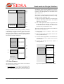
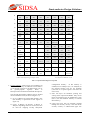
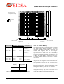
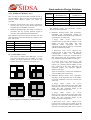
SIDSA
PL Configuration Memory, HW Probing Area and
Auxiliary Memory, respectively
Setting or clearing the values of the corresponding bits
in the system control registers (see later in the
document), the configuration of the memory can be
changed. This re-configuration can be made
dynamically; that is, non-reset between different
configurations are needed.
2.2. Buffer Access
The Data Buffer Area is located in $30 through $6F of
the internal data memory of the 8051. By default, this
portion of memory is not mapped, and the original
memory organization is obtained (see figure 1.3).
When buffer access area is enabled (first scratch pad
area is disabled because only one of them may be
active at a time), memories and registers from several
different blocks throughout the FIPSOC chip can be
accessed, depending on the access mode (these modes
will be described in detail later in the document):
• PL Block Regular Configuration Memory:
Locations $30 to $4F map buffer context #0 ($50
to $6F for buffer context #1). A write operation on
any of these locations writes data to all the DMCs
selected with the row and column mask registers
(mapped in the SFR area). A read operation should
only be done with one DMC selected, otherwise
the internal priority control circuit would select
only the one with the bigger column and mask
number. Configuration memory for the IO cells
and CAB-DMCs routing resources can also be
selected setting the corresponding bits included in
the row and column mask registers.
• PL Block LUT data memory: Locations $38 to
$3F map nibbles 0 to 7 of the Low Tile of the
DMC selected with the mask registers. Locations
$40 to $47 map the nibbles 0 to 7 of the High Tile
of the DMC selected to the mask registers. In both
cases, the lowest nibble is always used. Locations
$48 to $4F map nibbles 0 to 7 of both tiles, using
the four most significant bits of each location for
the nibble corresponding to the High tile and the
four least significant bits for the Low Tile. Several
DMCs can be selected for multiple write
operations, while only one for reading (the priority
circuit works like in the Regular Configuration
Memory mode). Locations $30 to $37 and $50 to
$6F are unused.
• PL Block Hardware Probing memory: This access
mode is intended to provide a fast way to probe
hardware signals in real time, both sequential and
combinational. Only the outputs of a Chip Quarter
are mapped, so the appropriate Chip Quarter must
be selected first with the Mapping Control
Registers (mapped in the SFR area)
Chapter 4. On-Chip Subsystems Interface
Semiconductor Design Solutions
• PL Block Hardware Writing mode: This access
mode is intended to provide a fast way to write in
the flip-flops of the sequential part of the DMCs in
real time. Only the DMCs of a Chip Quarter are
mapped, so the appropriate Chip Quarter must be
selected first with the Mapping Control
• CAB Configuration memory: CAB Configuration
is done by writing in non-buffered conventional
RAM memory. No multicontext operation is
allowed for the CAB. In this mode, the buffer
directly maps the whole CAB configuration
memory for read and write access. No context
transfer command is needed like for buffered
multicontext configuration memory (DMCs and
IOs).
Note that the regular configuration memory registers
and the hardware probing and flip-flop writing memory
locations may be also mapped in the external memory.
These access modes are independently configured and
may be used at the same time. These memory
locations cannot be reached from any program
running from the programmable logic configuration
memory (due to timing scheduling conflict)
The data in the Regular Configuration can be used
either for general purpose data or for configuring the
Programmable Logic Block. Data is stored in the
memory cells until a transfer command is sent (see PL
Block Document for further information).
2.3. Extended SFR map
The new special function registers added to the original
SFR map of the 8051 are dedicated to control,
configure and data transfer purpose. Only 18 of them
are related to the programmable blocks interface and
the system mapping control. In particular, SFR may be
grouped as follows:
• System Mapping Control Registers: These registers
are used by FIPSOC for memory organization
control and buffer access modes. They include:
a) Row and Column mask (two 16-bit registers
-ROW and COL- and one nibble of general control
register -RG2[7:4]-),
b) General Control registers (three locations, RG1,
RG2 and RG3),
c) Transfer command (one register, RGTX).
• Analog Control Registers: Ten registers are used
for (digital) data transmission with the CAB. Input
registers for the DACs are written here and output
registers from the ADCs and comparators are read
(DANA1 through DANA8 for DACs/ADCs
operations and outCOMP for comparators reading).
Control commands for this block are also issued
writing to one of these registers (ANAST).
6