1
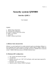
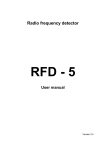
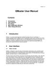
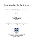
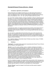
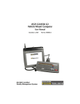
Version 5.0.-5/2012 QMaster User Manual Content: 1 2 3 4 5 6 1 Introduction User Interface MRA-5Q control elements DMC-3Q control elements Bus settings, interface QMI, QME Attachment Audio analysis – samples page 1 page 1 - 2 page 2 - 10 page 11 - 12 page 13 – 19 page 20 - 22 Introduction The detection of wireless listening devices is a complex problem because the miniaturized bugs are usually radiating very low power and their transmission is very often totally covered by legal local signals like TV, FM, digital broadcast, cell phones, WiFi etc. The solution is a very fast scanner MRA5Q or DMC-3Q the systems which are permanently comparing “clear’ background with current signals. QMaster is a windows based application suitable for remote control and monitoring of counter surveillance devices. QMaster is part of the QM-5000 system which consists of a PC, local QMI-2 interface or Ethernet QME-1 interface, RS-485 bus with additional audio line. QM-5000 allows to connect up to 128 devices on a single bus. Currently it is possible to connect MRA-5Q (or older MRA-3Q) memory radio analyzers and DMC-3Q mobile communication detectors to the common bus. 2 User Interface Basic concept QMaster is designed in a way that allows most frequently used functions to be accessible quickly and easily by pressing a button or activating other control element. Besides efficiency of control activation the priority lies in a transparent display of actual state of the controlled devices including detailed information about the currently selected device. The main window is split vertically in two parts: on the left there is the bus window, on the right there is the device window. The bus window lists the currently registered devices including their actual state, control buttons for working with the bus (e.g. adding/removing device), information about communication on the bus, and control elements for working with audio records. The device window contains detailed information about the currently selected device and controls for working with the device (tuning, measuring frequency, background inspection, working with alarms). The main menu contains supplementary functions for working with the current device. Additionally the main allows to change the application settings, save/load projects and invoke application help. All application elements are equipped with tooltips that give online context sensitive help. 1 Using mouse on graphical elements QMaster contains several graphical windows depicting channels of radio background, results of frequency spectrum analysis and the alarm history. You can use mouse to control these windows as follows: right button: select a region to zoom-in left button, double click: activate the corresponding frequency/channel (only frequency based windows) mouse wheel: zoom +/- 3 Control elements (for MRA-3Q) Fig. 1 Main application window (MRA-5Q). Devices 013, 014, 017 are connected to bus no.003 and device 015 to bus no. 088. Device no. 016 on the bus 088 is switched off. Device 013 has 50% pre-alarm and is detecting UMTS signal, device no. 014 has 66% pre-alarm and had 100% alarm on 11.6. at 08:04. Device no. 017 had last alarm on 11.6. at 09:08. Device no. 015 is in manual tuning, receiving frequency 946,10MHz. 2 Left side controls - buses & audio section: - File/Preferences: setting of communication (update) period, audio record length and audio record period during alarm, and alarm notification system - Device/Load Spectrum: select stored file .fsg = displays selected spectrum analysis - Device/Show Spectrum: displays last spectrum analysis - Section of registered Devices: BID = bus ID, ID = individual device ID (MRA or DMC), Status = alarm in defined communication system (GSM, DECT, WiFi, UMTS), Mode = (SCAN, OFF, Remote) and % of actual alarm, Last Alarm = time of the last alarm. Colors: Green = no alarm (all OK), Red = pre-alarm or alarm, Black = disconnected or off devices - Bus Manager: This window allows to Add Bus, Remove Bus, Edit Bus, Scan bus and Reset Bus. Current status of registered buses is displayed. How to register buses is described in chapter 5. Bus setting, interface QMI, QME (page 12 – 17) Next buttons: - Add: manually adds a new device and its name - Remove: removes selected device from the list - Delete Audio: deletes all audio records of selected device - Clear History: erases all alarm records of selected device - Hide Device Controls: switches off right part of the screen with the device controls 3 - History: activates history window of selected devices: Alarm history of selected devices. For MRA-5Q (ID 13, 14, 15) the percentage represents time information of an alarm to reach the 100% alarm (usually 10 minutes = 100%). For DMC-3Q (ID 17) the percentage represents signal strength of detected signal. - Communication window: The communication window contains messages about communication on the bus. In an errorless operation every data exchange on the bus ends with an OK message (green color). When ID FAIL (red color) appears the device with the particular ID is probably switched off or it is currently in a mode that does not support communication. When there are only FAIL messages very likely the problem is in a wrong setting of the communication port, interruption of the bus cable, or communicatio with non exiting device(s). Section Audio: - Speaker slider - setting the volume of playing the audio samples - Microphone slider - setting the microphone gain for audio recording - Record button - manual activation of audio sample recording. Record of selected length will be added to the record for the current device. The length of the sample is given by the choice in the settings dialog 4 - Show all button - show a dialog with a list of all audio samples. The dialog allows to play and delete the samples. The Audio Samples list contains: bus ID, device ID, number of the tuned channel, date and time of record, frequency of received signal (for signal level below 25% the frequency is marked by ?), signal Level (100% = maximum), Length of an audio sample. Button Play is re-paying selected record, Delete deletes selected record, Print prints on the printer, Close is closing the widow. Note: Audio samples are stored in the file like: .waw - Audio analysis: activates analysis of detected audio signal. This allows identification of different particularly digital signals Analysis of a DECT signal (peaks interval 10ms). The overview of frequently received signals and their acoustic records is in appendix (page 17 – 18). 5 - button Stop stops analysis and allows detail study of permanently changing signals or sporadic signals - button Run re-starts analysis - button Print printing of a graph on a printer - button Snapshot saves a picture into the file like .png Right side controls - device window (see Fig.1 section 3) Heading MRA-5Q 1.7CZ ID 15 BID 88 #0024 is identification of device version, connection to bus and varying value #xxxx is an internal ID of communication. The placement designation can be defined in Add window (bus section) or directly in placement line and confirm by ENTER. - SCAN switches to basic function (scanning = protect) - Automatic tuning activates function automatic tuning. Audio is permanently relayed. Automatic tuning can be stopped by a click on any arrow in Manual tuning section and the signal can be exactly tuned by manual tuning buttons. Click on the automatic tuning button returns back to automatic tuning. - Black bars in the Scan window are indicating the background, their size is corresponding to a background signal level of each occupied channel - Red bars in the upper part of the graph are showing new signals, their size corresponds to percentage of the alarm on the channel - s-meter is displaying RF signal level, maximum 100%. This value is transferred during automatic or manual tuning only. - Channel section: is displaying currently tuned channel number. Write any channel number and push enter – this channel is tuned. Arrows are changing channel up or down. - Add to BG and Delete from BG buttons are adding or deleting selected channel from the background - Background buttons are successively checking the background channels - Signal buttons are automatically tuning the first signal down, maximum of the signal around tuned frequency, or first signal up - Manual section: four arrows are slow or fast manual tuning up or down - Frequency section: Write required frequency and push enter or button Tune – this frequency will be tuned. - Measure button: tune the received signal to maximum and push this button. The frequency will be displayed in frequency window. Note: pushing of any button in section below s-meter are switching the MRA to manual tuning 6 - Commands section: - Store BG: erases old background spectrum and writes new background to MRA-5Q. In the second phase of background record the audio channel is opened and the automatic check of background spectrum can be monitored by the user. The background record length depends on density of local radio spectrum. After background record the MRA automatically switches to SCAN mode. - Update BG: the same procedure like Store BG, only the original spectrum is not erased and the higher new levels are add to the background. - Analyze Spectrum: Initiates detailed spectrum analysis 34 to 5900MHz on selected MRA-5Q Frequency spectrum in room 1005: Dominating frequencies: 100MHz = FM broadcast, 425MHz = CDMA, 950MHz = GSM base, 1887MHz = DECT, 2112MHz and 2166MHz = UMTS bases 7 Control elements in Frequency spectrum window: - F: Cursor frequency - G: Signal level on the cursor frequency - Color Spectrum: different colors and names for each displayed spectrum - Show only selected: displays only selected spectrum records - Zoom: left for frequency axis, right for vertical (signal level) axis - Print: print on the connected printer - Snapshot: print to a file - Load: load a file from a list of spectrum analysis .fsg - Save: saving the data for future (reference) image. More analysis can be displayed and compared at the same time. Data are saved like .fsg file. Comparison of two spectrum analysis. Zoomed frequency sector 380 to 525MHz. The strongest signal 421.6MHz, level G=70,9%. The main difference is a new signal (green) at 521MHz. - Background section: #6922 MRA current background ID channels=64 (12%) number of MRA background channels=64, it is 12% of the MRA background capacity 8 - List/Edit button opens Background Edit dialog window. Button Edit opens sub-window to change the background level for selected channel. When all required background level changes are completed push the Upload button to write the modified background into the MRA-5Q. - History button opens Background History window in which following info are displayed: Device ID, Date and time of background record, Background ID and number of busy channels in each record. Selected line can be edited by pushing List/Edit button – this command is opening the Background Edit window (see above). - Alarms section: - colors: green = OK, no alarms, red = pre-alarm or alarm #Alarms current / in MRA-5Q / in Qmaster history - Alarm level xx% maximum level of the current alarm (time criterion) - Alarm time total duration of the 100% alarm - Alarm table: chn = number of channel (0 – 511), rec = symbol loudspeaker – channel has an audio sample, alarm = current alarm level, max = maximal alarm level, D = this channel is in alarm table in MRA, sum = sum of time at which the signal was active, first = first occurrence of the signal on this channel, last = last occurrence of the signal on this channel, level = maximum signal level on this channel (for MRA-5Q and newer) - Device and History buttons = table of alarms in MRA only or in MRA + history file of the Qmaster - Add to BG = add selected channel to the MRA background - Delete = delete selected alarm channels from the MRA - Delete all = delete all alarms from the MRA 9 - History = show history of selected alarm channels History window: selected channels have different colors. Horizontal axis represents time and can be zoomed. Vertical axis is a percentage of an alarm level (100% = alarm on the device, below 100% = pre-alarm) - Clear history = clear history of selected alarm channels - Delete audio = delete audio records for the selected channels - Sync = make sure that the table is synchronized with the MRA - Select = select channels corresponding to various communication standards (GSM 900MHz, GSM 1800MHz, DECT, WiFi, UMTS) - Print = print the full contents of the table - Linear indicator in the right bottom corner = time behaviour of an audio record 10 4 DMC-3Q control elements Fig. 2: DMC-3Q control window: device DMC-3Q is version 1.8EN, ID 17 on the bus 088 and is located in room 1006. No alarm on the DMC-3Q is indicated at this moment. Left side controls – bus & audio section: All functions are equal to MRA-5Q (page 3) with exception in menu: - Device, there is possibility to change the DMC-3Q device ID After setting a new ID push OK, the device will re-numbered to required ID. If more devices should be re-numbered it is recommended to erase old numbers in the Devices list and after this to renumber next DMC-3Q. 11 Right side controls – selected device window: The principle of device control is the same like for MRA-5Q. The differences are visible from Fig.1 and Fig.2. - History button is opening history window. Different communication systems have different colors. Vertical axis represents signal level, horizontal axis is time information. Horizontal axis can be zoomed. Show only selected button selects required system only. History of DMC-3Q ID 17 in room no. 1006 - Detection frequency range of DMC-3Q is divided into 12 sections (0 to 11) and for each section the level of the detected signal is displayed (0 to 250). L/TH represents: current signal level / background for the frequency section. If L > TH the alarm is indicated. - Manual tuning: is activated by any tuning arrow or by Low / High band switch (more arrows = faster tuning). During manual tuning the s-meter indicates signal level of a received signal. Low band is tuning: 850 to 1000MHz and at same time 1700 to 2000MHz High band is tuning: 1700 to 2550MHz The received frequency is displayed below the fastest tuning down button. Audio analysis or audio Record can be activated in the manual tuning mode. 12 5 Bus settings, interfaces QMI & QME - Bus Manager: This window describes buses status and allows bus modifications. 1. COM buses (max.9) can be used with local QMI-2 interfaces. Adjust proper COM number – can be seen in the system (control panels, HW & sound, device manager, Ports COM and LPT) 2. TCP/UDP buses see: Setting of QME-1 below 3. push Add Bus 4. write Bus name 5. set port COM1 – COM9 for QMI, TCP/UDP for QME 6. The communication port for QME can be changed. Note: BUS IB and MAC address are initially set to 0 and this setting can not be changed. When the QME connects to server the ID and MAC address are automatically filled in. 7. For slow internet connection can be adjusted “Expected latency”. This can improve communication quality, but some functions like spectrum analysis or audio need stable internet communication. 13 QME-1 setting - user manual The QMaster works like a server receiving connection requests from interfaces QME-1 which are connected via Ethernet (internet). The control PC has to have fixed IPv4 address. This fix address together with communication port number must be set in the interface QME-1 (using QME buttons and display). After connection to the Ethernet the QME-1 obtains its own IP address (if the fix address is not also set in the QME-1) and then the QME-1 tests to connect to the QMaster PC. The QME-1 is repeating the connection request until the connection is established. PC / Server communication setting 1. Set the fix IP address at the Qmaster PC, do not use public IP address 2. Make sure that the communication port is open for TCP/IP (Transmission Control Protocol / Internet Protocol) and UDP (User Datagram Protocol). Default protocol setting is 4242 3. Be sure with the settings particularly if there is any firewall in the network or a router with NAT (Network Address Translation). In this case the configuration must be done by the IT specialist who will open selected port for communication and will set correct data steaming to the QMaster server. It can be achieved e.g. by unblocking of selected ports in Windows firewall or by NAT configuration to stream any packets sent to specific port to the QMaster server. Note: The QME and PC port numbers can be different, but it must be ensured that the packets will reach the proper destination. QME-1 setting: 1. Set the IP address and port on the QME-1 by service buttons and connect to Ethernet. Buttons left to right: MODE OK DOWN UP The QME-1 can use DHCP protocol and in this case the QME-1 obtains its IP address automatically. If there is no DHCP server in the network the IP and network gate must be set manually. 2. The QMaster does not need to know IP of QME-1, but all QME-1 must be properly adjusted. It means that the QME-1 can be simply connected to the network after firewall or NAT. 3. If the QMaster receives connection request from a QME-1 which has not been connected before a special dialog window is asking if the new QME should be connected. This dialog window is displaying MAC address which is corresponding with the QME-1 label. If the connection request is accepted the new QME-1 is add to the bus list. 14 Control elements, input outputs: 1. Connector POWER - power voltage 12V DC 2. Connector LAN RJ45 - connection to LAN or internet 3. DEVICE BUS 1 - CAN 9, bus for connection of MRA-5Q or DMC-3Q 4. DEVICE BUS 2 - CAN 9, parallel connected to BUS 1, for connection of second bus 5. 2 x 16 alphanumeric display 6. button RESET - processor reset, same function like power off / power on 7. trim VOLUME – earphone volume setting 8. EARPHONE – earphone connection for audio monitoring (2x 32ohm) 9. LED OK (green) – indicates correct communication 10. LED POWER (red) – indicates power supply Example of QME-1 setting - displayed information 1. Switching ON (after reset): QME-1 v 1.2 BUS ID = 61 Introductory info, SW version 1.2 Assigned bus ID = 61 Red LED POWER light 2. Connecting to LAN (or LAN disconnected): ETH CABLE CHECK BUS ID = 61 Connection of Ethernet cable testing Assigned bus ID = 61 Red LED POWER light 3. LAN cable connected: DHCP REQUEST BUS ID = 61 Checking IP address using DHCP protocol Assigned bus ID = 61 Red LED POWER light 15 4. LAN cable connected: ARP REQUEST BUS ID = 61 Checking connection to server using ARP protocol Assigned bus ID = 61 Red LED POWER light 5. Control PC switched ON (IP address 11.2.0.3): CONNECTING TO 011.002.000.003 Connecting to server IP 11.2.0.3 Red LED POWER light 6. Running QMaster on the control PC: CONNECTED #1234 UDP READY #1234 Correct function, correct communication Green LED OK and red LED POWER light Data stream increments the upper number Audio transmission increments lower number UDP READY – UDP audio streaming is ready 7. Qmaster ON, control PC switched OFF: DISCONNECTED UDP READY #1234 Disconnected Red LED POWER light 8. Communication breakdown: ARP REQUEST BUS ID=61 Red LED POWER light Display and green LED OK is responding with delay, system is trying to restore communication 16 9. LEDs on RJ45 connector -yellow = server connected -green = data stream QME-1 communication parameters settings Communication parameters are set by buttons which have following functions left to right: MODE OK DOWN UP Buttons are accessible after opening the box (4 screws) or by a match (max. 2,9mm) through 4 holes above left part of the display (after adjustment should be covered by supplied label) Setting of control PC’s or server’s IP address (this setting can be done with disconnected LAN) 1. Push MODE Server IP 111.222.333.444 First three numbers are flashing, using UP/DOWN buttons adjust desired number 2. Push OK – second three numbers are flashing, adjust desired number 3. Push OK – third three numbers are flashing, adjust desired number 4. Push OK – fourth three numbers are flashing, adjust desired number Note (example): IP address 11.2.0.3 is set like 011.002.000.003 5. Push MODE DHCP Enabled yes Confirm yes (recommended) if DHCP server is ready in local network. The server assigns IP address and sets gateway. If “no” is selected, the IP address of QME, gateways and masks must be set manually. Setting is similar like for IP server (see above) 6. Push MODE Port 04242 Setting port for UDP and TCP/IP communication. Confirm default = 04242 (the same default port is set in the bus manager in QMaster). Different setting of the port can be needed if the device or server is behind firewall which is blocking port 04242. In this case consult with local IT specialist. 17 7. Push MODE The QME-1 setting is finished, display returns to normal status and QME-1 is trying to establish communication with remote QMaster. In case of communication problems please consult with IT specialists at both ends of communication channel. 8. Stick on the label on the button holes to avoid any manipulation with the QME-1 settings Device bus The bus is connected to connectors CAN 9 marked DEVICE BUS 1 and 2. Buses 1 and 2 are parallel connected, usually is used only one (any) of them. The second is designated for e.g. test device or a device on a short bus. The bus carries the following signals: 1) Supply voltage for MRA-5Q devices, 12–17V 2) RS485 signal pair with proprietary data protocol 3) Audio line (switched on selectively by MRA-5Q or DMC-3Q) Layout of the device bus (QMI/MRA cable): CAN 9 pin Wire color Signal MRA-5Q ------------------------------------------------------------------------------------------------1 yellow AUDIO OPTIONS middle 2 gray GND CHARGER 3 white GND CHARGER 4 red +14 V CHARGER + 5 NC 6 shield GND CHARGER 7 green RS485 OPTIONS right channel 8 orange RS485 + OPTIONS left channel 9 NC When extending the bus the following wires should be paired: audio power RS485 1 and 2 3 and 4 7 and 8 18 A non-stabilized DC adapter 12V / 0.3-1A (max.20V) shall be connected to the POWER connector (the maximum current depends on the number of devices on the bus). The bus can be as much as 1200m long, wired from one device to another. If the bus is longer than 20m it is necessary to use a termination resistor at the most distant device (120 to 220 ohm connected between the green and the orange line, i.e. RS485+ and RS485-). The length of the audio cable to the PC (3.5mm jack) is not critical. If more devices (MRA-5Q and DMC-3Q are used additional power supplies can be used along the bus. Note: Because there are usually a large number of different IT devices connected to the LAN a number of parasite signals can go through to the MRA-5Q. The MRA-5Q is a very sensitive receiver and should be connected via as long as possible cable to the QME-1 to limit transfer of parasite receptions. Technical specification of QME-1: PC data interface RJ45 10/100Base T Device bus RS485 + audio line 300mV eff + power 12V Number of connected devices up to 128x MRA-5Q (with additional power supply) Bus length max. 1200m, parallel line configuration RS485 termination 120 to 220 ohm at the most distant device Number of bus wires 3 pairs (6 wires) + shielding Power current for MRA-5Q max 1A (32 devices) Current consumption 70mA + current according to number of MRA&DMC Input power voltage unstabilized 12 - 20V DC Audio filtering 300 - 3000 Hz Size 117 x 114 x 30 mm Weight 295g 19 6 Attachment Audio analysis (MRA-5Q) – samples WiFi 2,4GHz 100ms, span 100ms Video camera 2,4GHz span 50ms Voice span 100ms GSM voice – hopping span 50ms 20 GSM base 950MHz span 100ms Digital communication 394M span 100ms GSM data 950MHz span 100ms DECT 1890MHz span 50ms 21 TDMA 422MHz span 100ms 22