1
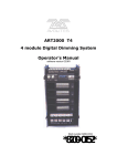
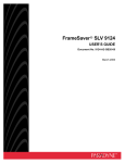
Connecting Peripheral Devices
Connecting Peripheral Devices - 1
Issue 2
November 1999
Connecting Peripheral Devices
Connecting Peripheral Devices
This section describes how to make the connections between the system and the following
peripheral devices:
n Monitor
n Keyboard
n Printer
n Modem
NOTE:
The modem section also includes an additional procedure that you need to perform if
the system has an AYC55 remote maintenance circuit card installed.
Connecting Peripheral Devices - 2
Issue 2
November 1999
Connecting Peripheral Devices
Connecting the Monitor
This section describes how to connect the monitor.
Required Cables for
the Monitor
MAP/5PV3 Y-Cable
Two cables connect the monitor to the system:
n Video cable connector
n Power cable or Y-cable (MAP/5PV3 only)
Video Cable Connector
3
2
1
caixycab LJK 080399
For all systems, the video cable connector has a video input connector at one end. The other
end of the cable is permanently attached to the monitor.
Power Cable
For all systems except the MAP/5PV3, the power cable has a male plug at one end and a
female plug at the other end. The power cable for the monitor connects directly into the
chassis.
For the MAP/5PV3, the Y-cable has 2 female plugs and 1 male. The male connector plugs
into a power cord. The female connector attached to the longer cord attaches to the monitor.
Continue, press PAGE DOWN.
Connecting Peripheral Devices - 3
Issue 2
November 1999
Connecting Peripheral Devices
Connecting Monitor
Cables
Click the graphic for a
larger view.
To connect the monitor cables:
1. Do one of the following:
n If the system is a MAP/5P, plug the video cable connector from the monitor
directly into the video connector located on the back of the MAP/5P or MAP/5PV3.
n If the system is a MAP/40P, plug the video cable connector from the monitor
Back View of the
MAP/5P and MAP/5PV3
directly into the video connector located on the back of the MAP/40P.
n If the system is a deskside or rack-mounted MAP/100P, plug the video cable
8
9
1
connector from the monitor directly into the video connector located on the back of
the video circuit card.
10
11
2
12
3
4
5
2. Tighten the thumb-screws on the video cable connector with your fingers or with a
6
7
small flat-blade screwdriver.
mpix5p LJK 072999
Back View of the
MAP/40P
3. Plug the female end of the power cable into the monitor.
4. Plug the male end of the power cable into a grounded AC outlet.
1
2
7
3
8
Continue, press PAGE DOWN.
4
9
10
5
6
h2mxr ear KLC 081997
Connecting Peripheral Devices - 4
Issue 2
November 1999
Connecting Peripheral Devices
Back View of the
Deskside MAP/100P
KEYBO ARD
COM M 2
10
9
1
7
8
2
Lucent
11
3
AY
C5 4
POWE R OK ( GREE N)
POWE R FA ULT (R ED )
11
P OWER OK (GR EE N)
P OWER FAU LT (R ED )
4
6
5
scinp003 K LC 011398
AY
C5
4
Back View of the
Rack-Mounted MAP/100P
L u
cent
9
11
12
P OWE R O K (G REEN )
P OWE R FAULT (R ED)
COMM 2
10
4
7
5
6
POW ER O K (G RE EN)
POW ER FAU LT ( RED )
KE Y BOA RD
5
8
3
2
1
s cinp006 KLC 032398
Procedure completed.
Connecting Peripheral Devices - 5
Issue 2
November 1999
Connecting Peripheral Devices
Connecting the Keyboard
Click the graphic for a
larger view.
A 6-pin female DIN receptacle is located in the back of the system. The male plug is provided
with the keyboard. Both of the connector assemblies are keyed to provide proper alignment.
Connector for the
Keyboard
NOTE:
Do not use the keyboard receptacle for any other purpose than to connect the keyboard.
Back View of the
MAP/5P and MAP/5PV3
8
9
1
10
11
2
12
3
4
5
6
7
mpix5p LJK 072999
Back View of the
MAP/40P
Continue, press PAGE DOWN.
1
2
7
3
8
4
9
10
5
6
h2mxr ear KLC 081997
Connecting Peripheral Devices - 6
Issue 2
November 1999
Connecting Peripheral Devices
Back View of the
Deskside MAP/100P
KEYBO ARD
COM M 2
10
9
1
7
8
2
Lucent
11
3
AY
C5 4
POWE R OK ( GREE N)
POWE R FA ULT (R ED )
11
P OWER OK (GR EE N)
P OWER FAU LT (R ED )
4
6
5
scinp003 K LC 011398
Back View of the
Rack-Mounted MAP/100P
AY
C5
4
Procedure completed.
L u
cent
9
11
12
P OWE R O K (G REEN )
P OWE R FAULT (R ED)
COMM 2
10
4
7
5
6
POW ER O K (G RE EN)
POW ER FAU LT ( RED )
KE Y BOA RD
5
8
3
2
1
s cinp006 KLC 032398
Connecting Peripheral Devices - 7
Issue 2
November 1999
Connecting Peripheral Devices
Connecting the Printer
A 25-pin D-subminiature female receptacle provides a parallel printer interface.
Use the instructions supplied in the manufacturer’s manual Users’ Guide 570 Printer or the
guide provided with your printer to unpack and install your printer. The following installation
overview supplements the information provided in your printer guide.
To connect the printer:
1. Unpack your printer according to the steps provided in your printer guide.
2. Install the ribbon cassette and paper as shown in your printer guide.
3. Set the ON-OFF switch of the printer to OFF.
4. Set the options as described in your printer guide.
NOTE:
The Lucent Intuity system works with the default settings for the 570 printer.
5. Connect the AC power cable to your printer.
Continue, press PAGE DOWN.
Connecting Peripheral Devices - 8
Issue 2
November 1999
Connecting Peripheral Devices
6. If your printer has a self-test feature, plug the AC power cable into a grounded wall
outlet and initiate the self-test by following the instructions in the printer guide. When
the self test is completed, turn the printer off and disconnect the power cable from the
wall outlet.
If your printer does not have a self-test feature, skip this step. Continue with Step 7.
7. Insert the male end of your cable into the 25-pin female parallel port connector.
8. Tighten the thumb-screws with your fingers or with a small flat-blade screwdriver.
9. Insert the other end of your cable into the parallel port on your printer.
10. Depending on your type of printer connection, either tighten the thumb-screws or
press the two wire-retaining clips together until you hear them click into the lock slots
on either side of the plug.
11. Plug the AC power cable into a grounded wall outlet.
Procedure completed.
Connecting Peripheral Devices - 9
Issue 2
November 1999
Connecting Peripheral Devices
Connecting a Modem
A modem can be used for connection:
n To the serial interface circuit card or COM1 to enable remote access
n Between a remote terminal and the network at a remote site
n To COM2 to enable remote login for Lucent support
NOTE:
If the system has an AYC54 remote maintenance board (RMB) circuit card, do not
make any connections to COM2. COM2 is disabled if the system has the RMB.
Modems attached to the disabled COM2 will not work.
n To the ACCX circuit card and breakout box for administration and networking
n To the AYC55 remote maintenance circuit card for remote login
The following sections outline how to connect and set up the 7400A, the 3820, 3910, and
U.S. Robotics modems.
CAUTION:
Before initializing any modem, confirm that an AYC54 remote maintenance circuit
card is not installed. The AYC54 has an on-board modem.
Continue, press PAGE DOWN.
Connecting Peripheral Devices - 10
Issue 2
November 1999
Connecting Peripheral Devices
Connecting the
7400A Data Module
Use the 7400A data module for connections to a distant modem or terminal to establish a
data call or for remote administration. You can connect the 7400A data module to either
COM1 or to the serial interface circuit card.
Setting Up the Hardware on the 7400A Data Module
Configure the modem for DCE operation. See “DTE/DCE Hardware Set Up” in Chapter 2,
“Installation,” in the Lucent 7400A Data Module User’s Manual, 555-020-706, for information
on DCE settings.
NOTE:
Make sure the EIA connector circuit card (located under the top panel of the 7400A data
module) is set to DCE. If it is not, unplug the circuit card and turn it to the DCE setting.
Connecting the 7400A to COM1
To connect the 7400A data module to COM1:
1. Attach a 9-pin to 25-pin adapter to COM1.
2. Attach an RS-232 cable to the adapter on COM1.
3. Attach the other end of the RS-232 cable to the 7400A data module.
4. Make the remaining connections.
See Lucent Intuity Messaging Solutions Release 5 Getting Connected, 585-313-703,
for more information on how to connect a data module.
Continue, press PAGE DOWN.
Connecting Peripheral Devices - 11
Issue 2
November 1999
Connecting Peripheral Devices
Connecting the 7400A Data Module to the Serial Interface Circuit Card
To connect the 7400A data module to the serial interface circuit card:
1. Attach the octopus cable (provided with the card) to the faceplate of the serial
interface circuit card.
2. Attach the modular jack end of the octopus cable to a DTE adapter.
3. Connect the DTE adapter to the 7400A data module.
4. Make the remaining connections.
See Lucent Intuity Getting Connected, 585-313-703, for more information on connecting a
data module.
Testing the Hardware Connections and Setup
To verify that you have completed the hardware connections and the set up completed
correctly:
1. Power up the system.
For more information on powering up your system, click on your system type:
n MAP/5P or MAP/5PV3
n MAP/40P
n MAP/100P
Continue, press PAGE DOWN.
Connecting Peripheral Devices - 12
Issue 2
November 1999
Connecting Peripheral Devices
2. Plug an RS-232 mini-tester into the COM2 port on the back of the system.
3. If the connections and set up are correct, DTR, RTS, and TD on the tester will light.
NOTE:
If the test fails, recheck the connections and setup.
Continue with Completing Setup on the 7400A Data Module.
Connecting Peripheral Devices - 13
Issue 2
November 1999
Connecting Peripheral Devices
Completing Setup on the 7400A Data Module
Set the options and interface baud rate on the 7400A data module. See 7400 Data Module
Option Settings and “Using the Front Panel” in the 7400A Data Module User’s Manual,
555-020-706, for details. In the set interface option menu, set the ANS ONLY? option to YES,
and then select the other options as listed in the following table:
Table: 7400 Data Module Option Settings
Option
Setting
Baud rate
1200 and 9600
ANS
AUTO
BRK DISK
LONG
CI
OFF
CH
OFF
CTS
ON
DCD
Normal
DSR
ON
DTR
50 Msec
DTR
FOLLOW
LL
OFF
REMLOOP
GRANT
RI
ON
(1 of 2)
Connecting Peripheral Devices - 14
Issue 2
November 1999
Connecting Peripheral Devices
Table: 7400 Data Module Option Settings
Option
Setting
RL
OFF
SIGLS DISC
OFF
TM
OFF
DONE
YES
(2 of 2)
Installing the Software for the 7400A Data Module
1. Log in as craft
2. Start at the Lucent Intuity Main Menu and select:
UNIX Management
Modem/Terminal Administration
Install Modem/Terminal Software
The system displays the Install Modem/Terminal Window.
3. Enter modem in the Device: field.
Continue, press PAGE DOWN.
Connecting Peripheral Devices - 15
Issue 2
November 1999
Connecting Peripheral Devices
4. Enter the appropriate port name in the Serial Port Number: field, for example,
/dev/tty00 or /dev/ttysaa, ... /dev/ttysah, etc.
5. Enter the appropriate modem speed in the Speed: field, either 9600, 4800, 2400,
1200, or 19200.
Setting Up a Terminal to Log In Remotely Through a 7400A Data Module
To set up a remote terminal through a 7400A data module:
1. Set the terminal line to 8 bits, no parity, and 1 stop bit.
2. Set the terminal line speed to the same as that of the modem to which the terminal is
connected.
NOTE:
See the documentation for the terminal for more information.
Procedure completed.
Connecting Peripheral Devices - 16
Issue 2
November 1999
Connecting Peripheral Devices
Connecting the
Paradyne 3820
Modem
The Paradyne 3820 modem is supported for connection to COM2. COM2 is reserved for
Lucent remote maintenance. Complete the procedures in this section to install the modem.
NOTE:
If the system is equipped with an AYC54 remote maintenance board (RMB), do not connect a
modem to COM2 for remote maintenance. Instead, connect the modem telephone line into
the RMB.
NOTE:
If the system has an AYC54 RMB, COM2 is disabled and will not support any connections.
NOTE:
Alarm is the name assigned to the COM2 serial port that is used for remote maintenance.
Determine your first step:
n If the Intuity system does not have an AYC55 remote maintenance circuit card,
continue with Connecting the 3820 Modem to the Platform.
n If the Intuity system has an AYC55 remote maintenance circuit card, continue with
Performing RMB Modem Administration and then Connecting the 3820 Modem to the
Platform.
Connecting Peripheral Devices - 17
Issue 2
November 1999
Connecting Peripheral Devices
Connecting the 3820
Modem to the
Platform
To connect the 3820 modem to the hardware platform:
1. Connect a 9-pin to 25-pin adapter to the 9-pin COM2 port on the back of the system.
2. Use a 25-pin to 8-pin adapter to complete the connection between the 9-pin COM2
port and the 8-pin modular cable that comes with the 3820 modem. First connect the
9-pin to 25-pin adapter to the 25-pin to 8-pin adapter and then connect the 25-pin to
8-pin adapter to the 8-pin modular cable.
3. Plug the 8-pin modular cable into the 3820 modem.
The system activates the RTS, CTS, and LSD indicators on the 3820 modem.
NOTE:
If you are using the modem for anything other than Lucent remote maintenance, use
the RS-232 adapter marked as DTE and the 6-pin cable to connect to the ports
(ttysaa, etc.) on the serial interface circuit card and the 3820 modem.
Configuring the 3820 Modem for Remote Administration
The 3820 modem can be configured in three ways:
n Powering up the system and performing an alarm origination download
NOTE:
The alarm origination download occurs during software installation. It is not necessary
to complete this procedure at this time.
Continue, press PAGE DOWN.
Connecting Peripheral Devices - 18
Issue 2
November 1999
Connecting Peripheral Devices
n Using the control panel on the 3820 modem after powering up
n Connecting the modem to a terminal that acts as a DTE
Typically the first method is the easiest way to configure the 3820 modem. Select the method
you want to use and follow the corresponding procedure.
Performing an Alarm Origination Download to Configure the 3820 Modem
To perform an alarm origination download:
CAUTION:
If you select this method, you must complete all connections to the system before
powering up.
1. Power up the system.
For more information on powering up your system, click on your system type:
n MAP/5P or MAP/5PV3
n MAP/40P
n MAP/100P
2. Log in as craft
Continue, press PAGE DOWN.
Connecting Peripheral Devices - 19
Issue 2
November 1999
Connecting Peripheral Devices
3. Start at the Lucent Intuity Main Menu and select:
Customer/Services Administration
Alarm Management
The system displays the Alarm Management Window.
Complete the fields as follows or as directed by the remote support center.
Product ID — Enter the unique product ID for the system.
Alarm Destination — Enter the telephone number of the remote maintenance
center or a number identified as the alarm destination.
Alarm Origination — Enter ACTIVE or INACTIVE
Alarm Level — Enter MAJOR or MINOR
Alarm Suppression — Enter ACTIVE or INACTIVE
Clear Alarm Notification — Enter ACTIVE or INACTIVE
4. Press F3 (Save) to save the alarm settings.
5. Press ENTER.
6. Press F8.
The system displays the alternate set of function keys.
Continue, press PAGE DOWN.
Connecting Peripheral Devices - 20
Issue 2
November 1999
Connecting Peripheral Devices
7. Press F1.
The system displays the Alarm Origination Test Window.
8. Select:
Execute Alarm Origination Test.
9. Press ENTER.
The system displays the Alarm Origination Confirmation Window.
10. Enter y to begin the alarm origination tests.
11. Press ENTER.
The system begins the alarm origination download which takes approximately 2 to 5
minutes to complete.
12. When the alarm origination download is complete, select Review Latest Test
Results.
If your screen displays the word Successful, your modem is configured.
Procedure completed.
Connecting Peripheral Devices - 21
Issue 2
November 1999
Connecting Peripheral Devices
Configuring the 3820 Modem Using Its Control Panel
Complete the following procedures to configure the 3820 modem using its control panel.
NOTE:
Once your modem is configured, save the configuration so that if the modem loses power,
you will not need to repeat these configuration steps.
The configuration process can be divided into the following procedures:
n Selecting the UNIX dial default factory configuration
n Setting the Async DTE rate to the required speed
n Setting the DTR action and the DSR control to standard RS-232
n Setting the error control mode to buffer mode
Using the Diagnostic Control Panel on the 3820 Modem
The 3820 modem has a Diagnostic Control Panel (DCP) which is the user interface to the
modem.
Continue, press PAGE DOWN.
Connecting Peripheral Devices - 22
Issue 2
November 1999
Connecting Peripheral Devices
The following table shows how to use the keys on the DCP.
Table: Key Functions on the 3820 Modem Diagnostic Control Panel
Key
Function
UP ARROW
Moves up one level from the current display
DOUBLE UP
ARROW
Returns the display to the top-level menu
LEFT ARROW
Moves the cursor or display to the left
RIGHT ARROW
Moves the cursor or display to the right
F1, F2, F3
Selects items displayed directly above each key
Tip:
Press the RIGHT ARROW key to scroll forward and LEFT ARROW key to scroll backward.
Selecting the UNIX Dial Default Factory Configuration
To select and save the “UNIX Dial” default factory setting to the “Active (Saved)” configuration
area:
1. Turn the modem off and then back on.
2. Press the RIGHT ARROW key on the DCP until Configure comes into view.
Continue, press PAGE DOWN.
Connecting Peripheral Devices - 23
Issue 2
November 1999
Connecting Peripheral Devices
3. Press the function key below “Configure“ to select the “Configure” branch of the
menu.
The LCD displays "Ld EditArea frm".
4. Press the RIGHT ARROW key or the LEFT ARROW key until Factory comes into
view.
5. Press F1 to display the factory preset configuration.
The LCD displays "Async Dial”.
6. Press the RIGHT ARROW key or the LEFT ARROW key until Unix Dial comes into
view.
7. Press the function key below “Unix Dial” to select the “Unix Dial” default factory
setting.
The LCD displays Choose Function and then Edit and Save.
8. Press F3 (Save) to save the selected Unix Dial default factory setting.
The LCD displays Sav EditArea to and then Active (Saved).
9. Press F1 to save the configuration to the Active (Saved) area.
The LCD displays "Command Complete".
10. Press the DOUBLE UP ARROW key to return to the top-level menu.
Continue, press PAGE DOWN.
Connecting Peripheral Devices - 24
Issue 2
November 1999
Connecting Peripheral Devices
Setting the Async DTE Rate to the Required Speed on the 3820 Modem
To set the Async DTE rate to the required speed, complete the following procedure:
1. Press the RIGHT ARROW key or the LEFT ARROW key on the DCP until
“Configure” comes into view.
2. Press the function key below “Configure” to select the “Configure” branch of the
menu.
The LCD displays “Ld EditArea frm.”
3. Press the RIGHT ARROW key or the LEFT ARROW key until “Active (Saved)”
comes into view.
4. Press F1 to select the “Active (Saved)” configuration area.
The LCD displays “Choose Function” and then “Edit and Save.”
5. Press F1 (Edit) to edit the “Active (Saved)” configuration area.
The LCD displays “Edit StrapGroup” and then “DTE Interface.”
6. Press F1 to edit the DTE Interface.
The LCD displays “Async/Sync Mode.”
7. Press F1 (Nxt) until “Async DTE Rate” comes into view.
Continue, press PAGE DOWN.
Connecting Peripheral Devices - 25
Issue 2
November 1999
Connecting Peripheral Devices
8. Press the RIGHT ARROW key or the LEFT ARROW key until the desired speed
comes into view.
NOTE:
The desired speed for networking is 19,200 baud. The desired speed for
administration is 9600 baud.
9. When the desired speed comes into view, press F2 to set the Async DTE Rate.
10. Continue with Setting the DTR Action and DSR Control to Standard RS-232 on the
3820 Modem.
Connecting Peripheral Devices - 26
Issue 2
November 1999
Connecting Peripheral Devices
Setting the DTR Action and DSR Control to Standard RS-232 on the 3820 Modem
NOTE:
Do not return to the top-level menu after you complete this procedure.
To set the DTR action to standard RS-232 on the 3820 modem:
1. Press F1 (Nxt) until “DTR Action” comes into view.
2. Press the RIGHT ARROW key or the LEFT ARROW key until “Stndrd_RS-232”
comes into view.
3. Press F2 to set the DTR Action.
4. Press F1 (Nxt) until “DSR Control” comes into view.
5. Press the RIGHT ARROW key or the LEFT ARROW key until “Stndrd_RS-232”
comes into view.
6. Press F2 to set the DSR control.
7. Continue with Setting the Error Control Mode to Buffer Mode on the 3820 Modem.
Connecting Peripheral Devices - 27
Issue 2
November 1999
Connecting Peripheral Devices
Setting the Error Control Mode to Buffer Mode on the 3820 Modem
NOTE:
Do not return to the top-level menu after you complete this procedure.
To set the error control mode to buffer mode:
1. Press the UP ARROW key to move up one level from the current display.
The LCD displays “Edit StrapGroup.”
2. Press the RIGHT ARROW key or the LEFT ARROW key until “V42/MNP/Buffer”
comes into view.
3. Press F1 to edit “V42/MNP/Buffer.”
The LCD displays “Err Control Mode.”
4. Press the RIGHT ARROW key or the LEFT ARROW key until “BufferMode” comes
into view.
5. Press F2 to select “BufferMode.”
6. Press the UP ARROW key to move up one level from the current display.
The LCD displays “Edit StrapGroup.”
Continue, press PAGE DOWN.
Connecting Peripheral Devices - 28
Issue 2
November 1999
Connecting Peripheral Devices
7. Press the UP ARROW key to move up one level from the current display.
The LCD displays “Choose Function” and then “Edit and Save.”
8. Press F3 (Save) to save the configuration you just edited to the “Active (Saved)”
configuration area.
The LCD displays “Sav EditArea to” and then “Active (Saved).”
9. Press F1 to confirm the save request.
The LCD displays “Command Complete.”
10. Press the DOUBLE UP ARROW key to return to the top-level menu.
Procedure completed.
Connecting Peripheral Devices - 29
Issue 2
November 1999
Connecting Peripheral Devices
Configuring the 3820 Modem Through a Terminal
To configure the 3820 modem through a terminal rather than on the control panel of the
modem:
1. Connect a terminal to the 3820 modem.
2. See the documentation specific to the terminal and make sure that the terminal is
acting as a DTE.
3. Set the terminal line to 8 bits, no parity, and 1 stop bit.
4. Set the baud rate of the terminal line to the required modem speed.
For example, for the 3820 modem attached to the remote maintenance port, set the
terminal line to 9600 baud.
5. Enter AT on the terminal.
If the modem returns “OK,” it is ready to accept AT commands from the terminal. If the
modem does not return OK, check the connection and the terminal setup.
Continue, press PAGE DOWN.
Connecting Peripheral Devices - 30
Issue 2
November 1999
Connecting Peripheral Devices
6. Enter the following AT command:
AT&T&F3L0&D2&S1\N0\Q3S41=<dial line rate>S2=128&W0
where <dial line rate> is one of the following values:
3=9600
7=1200 (V.22)
5=4800
8=1200 (212A)
6=2400
20=19200
For example, to set the 3820 modem for COM2 use where the baud rate is 9600,
enter 3 as the <dial line rate> as shown below:
AT&T&F3L0&D2&S1\N0\Q3S41=3S2=128&W0
The modem should return “OK.”
Procedure completed.
Connecting Peripheral Devices - 31
Issue 2
November 1999
Connecting Peripheral Devices
Configuring the
3910 Modem
Complete the following procedures to configure the 3910 modem:
Determine your first step:
n If the Intuity system does not have an AYC55 remote maintenance circuit card,
continue with Using the Diagnostic Control Panel on the 3910 Modem.
n If the Intuity system has an AYC55 remote maintenance circuit card, continue with
Performing RMB Modem Administration and then Using the Diagnostic Control Panel
on the 3910 Modem.
Connecting Peripheral Devices - 32
Issue 2
November 1999
Connecting Peripheral Devices
Using the Diagnostic Control Panel on the 3910 Modem
The 3910 modem has a Diagnostic Control Panel (DCP) that is the user interface to the
modem. The following table shows how to use the keys on the DCP.
Table: Key Functions on the 3910 Modem Diagnostic Control Panel
Key
Function
UP ARROW
Moves up one level from the current display
DOUBLE UP
ARROW
Returns the display to the top-level menu
LEFT ARROW
Moves the cursor or display to the left
RIGHT ARROW
Moves the cursor or display to the right
F1, F2, F3
Selects items displayed directly above each key
Tip:
Press the RIGHT ARROW key to scroll forward and the LEFT ARROW key to scroll backward.
The appropriate factory setting for the 3910 modem is “Async Dial”.
To select and save the “Async Dial” factory setting to the “Active (Saved)” configuration area:
1. Turn the modem off and then back on.
2. Press the RIGHT ARROW key or the LEFT ARROW key on the DCP until
“Configure” comes into view.
Continue, press PAGE DOWN.
Connecting Peripheral Devices - 33
Issue 2
November 1999
Connecting Peripheral Devices
3. Press the function key below “Configure“ to select the “Configure” branch of the
menu.
The LCD displays “Ld EditArea frm.”
4. Press the RIGHT ARROW key or the LEFT ARROW key until “Factory” comes into
view.
5. Press F1 to display the factory preset configuration.
The LCD should display “Async Dial.”
6. Do one of the following:
n If “Async Dial” is displayed, skip to Step 7.
n If “Asynch Dial” is not displayed, press the RIGHT ARROW key until “Asych
Dial” is displayed on the LCD.
7. Press the function key directly under the “Async Dial” factory setting to save the
setting.
“Choose Function” appears and then “Edit and Save.”
8. Press F3 to save the configuration to the “Active (Saved)” area.
The LCD displays “Sav EditArea to”.
9. Press the RIGHT ARROW key until “Active (Saved)” appears.
Continue, press PAGE DOWN.
Connecting Peripheral Devices - 34
Issue 2
November 1999
Connecting Peripheral Devices
10. Press the function key below “Active (Saved)” to save the configuration to the “Active
(Saved)” area.
The LCD displays “Command Complete”.
The modem is now configured with the “Async Dial” setting.
11. Press the DOUBLE UP ARROW key to return to the top-level menu.
Procedure completed.
Connecting Peripheral Devices - 35
Issue 2
November 1999
Connecting Peripheral Devices
Connecting the U.S.
Robotics Modem
The U.S. Robotics modem is supported for connection to COM2. COM2 is reserved for
Lucent remote maintenance. Complete the procedures in this section to install the modem.
NOTE:
Alarm is the name assigned to the COM2 serial port that is used for remote maintenance.
Connecting the U.S. Robotics Modem to the Platform
To connect the U.S. Robotics modem to the back of the system:
1. Connect a 9-pin to 25-pin cable to the 9-pin COM2 port.
2. Connect the 25-pin end of the cable to the modem.
The system activates the AA, TR, and CS indicators on the modem.
Continue, press PAGE DOWN.
Connecting Peripheral Devices - 36
Issue 2
November 1999
Connecting Peripheral Devices
Configuring the U.S. Robotics Modem Through a Terminal
To configure the modem through a terminal rather than on the control panel of the modem:
1. Connect a terminal to the modem.
2. See the documentation for the terminal and make sure that the terminal is acting as a
DTE.
3. Set the terminal line to 8 bits, no parity, and 1 stop bit.
4. Set the baud of the terminal line to the required modem speed.
For example, for the U.S. Robotics modem attached to the remote maintenance port,
set the terminal line to 9600 baud.
5. Enter AT on the terminal.
The modem displays “OK”.
NOTE:
If the modem does not display “OK”, check the connection and the terminal setup.
6. Enter the following AT command:
AT&T&F1&D2&B0&S1S0=1S2=128&W0
The modem displays “OK”.
Continue, press PAGE DOWN.
Connecting Peripheral Devices - 37
Issue 2
November 1999
Connecting Peripheral Devices
7. Disconnect the terminal.
8. Connect the modem to the communication port (COM1 or COM2).
The system activates the RTS, CTS, and LSD indicators on the modem.
Procedure completed.
Connecting Peripheral Devices - 38
Issue 2
November 1999
Connecting Peripheral Devices
Performing RMB
Modem
Administration
Important:
Complete this procedure only if the Intuity system has an AYC55 remote maintenance circuit
card. Do not complete this procedure if the system has an AYC54 modem.
To perform RMB modem administration:
1. Log in as craft
2. Start at the Lucent Intuity Main Menu and select:
UNIX Management
RMB Modem Administration
The system displays the following message:
Please specify the modem used:
1) Internal (AYC54)
2) Paradyne 3820
3) Paradyne 3910
4) custom modem initialization string, for example AT&F&R1
Enter your choice (number between 1 and 4, otherwise program
terminates):
Continue, press PAGE DOWN.
Connecting Peripheral Devices - 39
Issue 2
November 1999
Connecting Peripheral Devices
3. Type the modem type as 1, 2, or 3, or type 4 for a custom modem initialization string.
NOTE:
If you entered 4, type the custom modem initialization string as prompted.
4. Press ENTER.
The system returns to the UNIX Management Window.
5. Press F6 (Cancel) to return to the Lucent Intuity Main Menu.
Procedure completed.
Connecting Peripheral Devices - 40
Issue 2
November 1999
Lucent Intuity Main Menu
Lucent Intuity
Main Menu
Connecting Peripheral Devices - 41
Issue 2
November 1999
Install Modem/Terminal Window
Install
Modem/Terminal
Window
Connecting Peripheral Devices - 42
Issue 2
November 1999
Alarm Management Window
Alarm
Management
Window
Connecting Peripheral Devices - 43
Issue 2
November 1999
Alarm Origination Test Window
Alarm
Origination Test
Window
Connecting Peripheral Devices - 44
Issue 2
November 1999
Alarm Origination Confirmation Window
Alarm
Origination
Confirmation
Window
Connecting Peripheral Devices - 45
Issue 2
November 1999
UNIX Management Window
UNIX
Management
Window
Connecting Peripheral Devices - 46
Issue 2
November 1999
Circular DIN 6-Pin Connector for the Keyboard
Figure: Circular
DIN 6-Pin
Connector for
the Keyboard
Connecting Peripheral Devices - 47
Issue 2
November 1999
Back View (MAP/5P and MAP/5PV3)
Figure:
Back View
(MAP/5P and
MAP/5PV3)
1
2
3
4
5
6
7
8
9
10
11
12
Power supply fan intake
Keyboard connector
Mouse connector (not used)
COM1
COM2 (MAP/5P only) or USB
ports (MAP/5PV3 only, not
used)
Parallel port
Monitor connector
AC power supply outlet
(MAP/5P only)
Dress cover lock
AC voltage selector switch
AC power inlet receptacle
COM2 (MAP/5PV3 only)
8
9
1
10
11
2
12
3
4
5
6
7
mpix5p LJK 072999
Connecting Peripheral Devices - 48
Issue 2
November 1999
Back View of the MAP/40P
Figure: Back
View of the
MAP/40P
1 AC power inlet receptacle
2 AC power supply outlet
3 External SCSI I/O
connector
4 Parallel port
5 COM2
6 Keyboard connector
7 Power supply fan exhaust
8 Mouse connector
9 Video connector
10 COM1
1
2
7
3
8
4
9
10
5
6
h2mxrear KLC 081997
Connecting Peripheral Devices - 49
Issue 2
November 1999
Back View of the Deskside MAP/100P
Figure: Back
View of the
Deskside
MAP/100P
1 Video circuit card
(PCI slot 1)
2 P5 200 MHz CPU with
COM1 (slot 17)
3 Remote maintenance
circuit card (ISA slot 16)
4 ON/OFF power switch with
protective guard
5 AC power inlet receptacle
6 Fuse
7 Power supply 1
8 Power supply 2
9 COM2 port
10 Keyboard connector
11 Power supply status LED
KEYBOARD
10
COMM 2
9
1
8
7
2
Lucent
11
AYC54
3
POWER OK (GREEN)
POWER FAULT (RED)
11
POWER OK (GREEN)
POWER FAULT (RED)
4
6
5
scinp003 KLC 011398
Connecting Peripheral Devices - 50
Issue 2
November 1999
Back View of the Rack-Mounted MAP/100P
AY C54
Figure: Back
View of the
Rack-Mounted
MAP/100P
Lucent
9
12
POWER OK (GREEN)
POWER FAULT (RED)
COMM 2
10
11
4
7
5
8
6
POWER OK (GREEN)
POWER FAULT (RED)
KEYBOARD
5
3
2
1
scinp006 KLC 032398
1 Fuse
2 AC power inlet receptacle
3 ON/OFF power switch with
protective guard
4 Power supply status LED
5 Power supply 1
6 Power supply 2
Connecting Peripheral Devices - 51
7 Keyboard connector
8 COM2 port
9 Remote maintenance circuit card
(ISA slot 16)
10 P5 200 MHz CPU with COM1
(slot 17)
11 Video circuit card (PCI slot 1)
12 Remote maintenance circuit card
Issue 2
November 1999
Y-Cable (MAP/5PV3 Only)
Figure:
Y-Cable
(MAP/5PV3
Only)
3
2
1
caixycab LJK 080399
1 Connect to the monitor
2 Connect to the platform
3 Connect to the power cord
Connecting Peripheral Devices - 52
Issue 2
November 1999