1
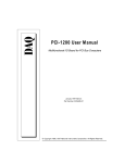
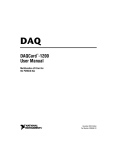
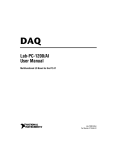
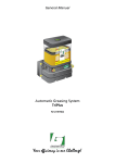
Technical Brief: TB-101 INTEGRATED CIRCUITS DIVISION Optically Isolating an I2C Interface Using IXYS Integrated Circuits Division’s CPC5902 and CPC5903 TB-101 December 5, 2012 www.ixysic.com 1 Technical Brief: TB-101 INTEGRATED CIRCUITS DIVISION Abstract: The ideal model of an open-drain bus as a simple, shared pull-up resistor is no longer instantaneously valid when using bus isolators with real-world propagation delays. If the delays are not considered in the design of the hardware, then there may be differences in the number of rising or falling edges seen at each isolated bus. Introduction to the I2C Bus 1 The I2C bus is a set of hardware and software rules that allows communication between multiple devices over a shared, two-wire interface. In operation the bus uses one line (SDA) for data and the other line (SCL) for clock. In standard mode (100kbps) or fast mode (400kbps), each of the two wires can be pulled high through an external pull-up resistor. Thus if any of the multiple devices asserts a logic low onto either line of the bus, the logic low is seen at all devices. Rules defining master and slave devices determine who is allowed to drive the bus lines, and when. The bus specifications were defined and are maintained by Philips Semiconductors (now known as NXP Inc.)1 The device that is acting as the bus master drives the clock line (SCL) when communicating with slave devices. Any addressed slaves respond at a time defined by this clock by asserting the data (SDA) line using a specified protocol. The simplest system contains only one master device with all other devices always responding as slaves. In more complex systems multiple devices can take turns being bus master, and the SCL line will be driven by whichever device is master at that time. There are many applications requiring ground isolation or logic-level translation between devices where the simple I2C protocol is very useful. The small number of wires (2) minimizes the required number of isolators and keeps down the cost of the isolated systems, Figure 1 although each direction of the wire has generally required its own isolator. Systems in which the bus can be isolated such that only slave devices exist on one side of the isolation barrier do not need bidirectional isolation of the SCL line. More specifically, a bus containing only I2C slaves that do not need to implement clock stretching (in order to slow down the bus to the speed that they can use) does not need bidirectional isolation of the SCL line. The CPC5903 optical isolator is configured for use in these systems (see Figure 1): It has one bidirectional path (for SDA) and one unidirectional path (for SCL). Systems in which devices on either side of the isolation barrier may function as bus master need bidirectional isolation of both lines; the CPC5902 is configured for this application (see Figure 1). The CPC5902 also functions very well when one channel is only used in a unidirectional manner. It supports these applications: • Slave-only-on-SideB • Clock-stretching-slave-on-SideB • Bus-master-on-SideB and should be used for slave-only systems in which yet-unknown future devices might be attached to the isolated bus at some later time. The remainder of this Technical Brief discusses optical, bidirectional bus isolators, of which the CPC5903 has one, and the CPC5902 has two. CPC5902 & CPC5903 Application Diagrams VDDA VDDA VDDA SCL_A SDA_A I2C Master VDDB VDDB VDDB CPC5902 I2C Slave VDDA VDDA VDDA SCL_B SCL_A SDA_B SDA_A I2C Master I2C Slave I2C Master 1 2 SCL_B CPC5903 I2C Slave Optical Isolation Barrier VDDB VDDB VDDB SDA_B I2C Slave I2C Slave Optical Isolation Barrier NXP Semiconductor, “I2C-bus Specification and User manual” UM10204_3, June 2007 www.ixysic.com December 5, 2012 Technical Brief: TB-101 INTEGRATED CIRCUITS DIVISION 2 Isolating a Bidirectional Open-Drain Bus The I2C bus, which contains at least one bidirectional open-drain bus, does not easily lend itself to optical or other isolation. The ideal bus model of the SDA line is a shared pull-up resistor connected to bidirectional I/O pins at multiple devices. The bidirectionality of the bus Figure 2 in an isolated bus system causes a departure from this ideal model: If a real-world active bus repeater or bus isolator is allowed to drive its own input low at both its I/O pins, then the bus will latch the first logic low asserted, and allow no further activity! This Bus Repeater Latches Up VDDB 499Ω VDDA IOB 499Ω /gateB1 IOA 20pF Bus Repeater without bus latch protection method 20pF /gateA2 SideB I2C Driver VIN /gateA1 0V Figure 3 Bus A and Bus B Both Stuck Low At 2μs VIN goes HI, but IOA and IOB are stuck LO VIN IOA IOB December 5, 2012 www.ixysic.com 3 Technical Brief: TB-101 INTEGRATED CIRCUITS DIVISION One way to avoid the latch-up problem is to use a separate input and output pin on all devices at SideB (so that when the repeater output is driven low it does not drive the repeater input low). There are some peripherals, which have been intentionally designed to run with standard optoisolators, that do utilize this extra wire to provide separate data input and output wires at devices at SideB. This does require an extra package Figure 4 pin, and prohibits the use of most I2C devices (without the extra pin) at the isolated SideB bus. This also complicates debugging of the bus because most I2C bus analyzers do not have a provision for the third wire, and thus can only be used on SideA of the isolated bus. Separate In and Separate Out at SideB VDDB VDDA Bus Repeater Separate IN / OUT 499Ω OB 499Ω 20pF IOA 20pF VDDB 499Ω IB VIN SideB Driver 0V SideB Receiver 4 www.ixysic.com December 5, 2012 Technical Brief: TB-101 INTEGRATED CIRCUITS DIVISION A different method of bus logic low latch-up prevention is used in the CPC5902 and CPC5903, and by some other bus repeaters and isolators. This method uses non-standard three-level logic at the isolated SideB. This method only requires 2 wires, and works with all Figure 5 I2C devices and bus analyzers. It also works with the separate data-in/data-out pin devices if the data-in and data-out pins are shorted together at SideB. Three-Level System at Side B VDDA 499Ω Bus Repeater Non-Standard Levels at SideB VOLB = 0.23VDDB VILB = 0.2VDDB IOA VDDB 499Ω IOB 20pF 20pF VDC = 0.23 • VDDB + VDC = 0.2 • VDDB VIN SideB I2C Driver 0V If the repeater output driver is designed such that it can only drive VOLB down to 0.23*VDD, and the receiver input threshold, VILB, is designed to switch near 0.2*VDD, then the repeater output cannot drive its own input low. The I2C specification defines VIL to be any input voltage below 0.3*VDD . All devices attached to the bus that meet this spec will correctly see the non-standard output level, VOLB, as an asserted logic low. When using this method, a careful designer must pick the value of pull-up resistors on SideB of the bus such that all devices on that bus can drive lower than December 5, 2012 VILB=0.2*VDD . This may require picking a slightly higher value pull-up resistor. As an example, consider a system in which there are both 3mA-drive I2C standard-mode devices and 6mA-drive I2C fast-mode devices on the isolated SideB of the bus. The pull-up resistor value in a usual system must be picked so that the standard-mode (weakest) device will pull the bus lower than 0.3*VDD when asserted low. However, the pull-up resistor must be picked so that the weakest device will pull lower than 0.2*VDD when used at the SideB of the CPC5902 and CPC5903 isolators, as described below. www.ixysic.com 5 Technical Brief: TB-101 INTEGRATED CIRCUITS DIVISION 2.1 Three-Level System Pull-Up Resistor Selection If the VDDB supply voltage is specified to be minimum 3V to maximum 3.6V, then the minimum value of the pull-down resistance for usual, standard levels would be that value that pulled the bus down to or below 0.3*VDD when VDDB=3.6V. At 3.6VDD , 0.3*3.6=1.08V, and 3.6V-1.08V=2.52V, which must drop across the pull-up resistor when the minimum guaranteed output drive of 3mA is applied. Thus the minimum value of resistor for this standard-level, standard-mode system is 2.52V/3mA = 840. The designer would need to pick a standard value which is slightly greater than this; how much greater depends on the guaranteed resistor tolerance, perhaps picking 866 for 1% tolerance resistors. For the CPC5902 and CPC5903 non-standard level SideB, for VDDB between 3V and 3.6V, use the same method, but require that the bus pull down to 0.2*VDDB when VDDB=3.6V. At 3.6VDD , 0.2*3.6=0.72V and 3.6V-0.72V=2.88V, which must drop across the resistor when the 3mA minimum drive is applied. Thus the minimum value of resistance for the CPC5902 and CPC5903 family is 2.88V/3mA=960. A standard value of 1% tolerance resistor that will stay above this minimum is 976. Thus, in this example, the use of CPC5902 or CPC5903 requires a 976 RPULLUP to guarantee operation under all conditions, while a standard level implementation would have required 866. 6 Note that I2C fast-mode-capable devices guarantee 6mA of output drive, and therefore could use smaller resistors, but the presence of the 3mA drive standard mode devices on SideB of the bus make the larger resistance mandatory to insure their operation. In practice, most manufacturers design their standard mode output drivers to supply more than the required 3mA of the I2C-specification, and so the values used above prove to be quite conservative. Also note that SideB of one CPC5902 or CPC5903 cannot be connected to SideB of another CPC5902 or CPC5903 if communication of one through the other is required. This is because the output logic low of one will not be seen as a valid logic low at the input of the other. SideB of isolators can be connected to SideA of more isolators if cascaded operation is desired. www.ixysic.com December 5, 2012 Technical Brief: TB-101 INTEGRATED CIRCUITS DIVISION 3 Time Delays in Bus Repeaters and Isolators Another way in which an isolated bus system departs from the ideal pull-up resistor model is in the timing of transmitted versus received data. For an ideal, non-isolated system of multiple devices tied to the same pull-up resistor, there is very little time delay between when each device on the bus sees the level go to an asserted logic low or return high. Unfortunately, delays of tens to hundreds of nanoseconds can exist within isolators, and such delays must be carefully accounted for to insure legal values of specifications such as data setup and data hold times. The LED-photodetector cascade within an optoisolator is inherently a lowpass filter. The primary bandwidth Figure 6 limiter is usually capacitance at the photodetector, which must be charged and discharged by the small photo-generated current. In a logic optoisolator this electro-optical filter is then followed by a comparator. This low-pass filter suppresses very short logic pulses, and adds a time delay to any logic signal applied. Later sections of this paper will show that the effects of this filter on pulse-widths and delays can be modified by using different latch-up suppression methods. In this Tech Brief, simple, buffered RC filters are used to model the low-pass characteristic, and a pair of logic inverters used to model the high-gain comparator (see Figure 6). This circuit is used elsewhere in this Tech Brief as a circuit block named “Filtered 60ns Delay.” “Filtered 60ns Delay” Circuit Node “RC” R 10kΩ IN OUT C 8.2pF For applied pulse-widths greater than 5 times the RC time constant (5RC) at Node “RC,” this circuit exhibits nearly the same filtering for going-low and going-high signals. For example, the “Filtered 60ns Delay” circuit delays the rising edge of a 400ns pulse by 60ns and the falling edge by 78ns. The small asymmetry is because the comparator switching threshold voltage is lower than VDD /2. An asymmetry in this direction generally also exists in real logic optoisolators when the capacitance at the photodetector can be charged quickly by photocurrent from an over-driven LED, but can only self-discharge at a lower rate. December 5, 2012 However, a low-pass filtered comparator is a non-linear circuit even for digital signals. When applied after a “long” (greater than 5RC) wait, even a short pulse will ramp Node RC up from zero to the comparator switching threshold voltage in the expected amount of time (see Figure 7). But if the pulse width is not greater than or equal to 5RC, then the Node RC does not ramp all the way to VDD after the rising edge is applied (see Figure 8). Thus when the falling edge arrives and the Node RC starts to go negative, it does not need to drop all the way from VDD down to the comparator threshold. www.ixysic.com 7 Technical Brief: TB-101 INTEGRATED CIRCUITS DIVISION Figure 7 below shows the Node RC charging all the way to VDD for a nominal input pulse. The going-low delay is similar to the going-high delay, and the output Figure 7 Applied Pulse Greater Than 5RC Figure 8 below shows the Node RC barely charging up to the comparator threshold voltage, and very quickly going below it when the falling edge starts to pull Node RC negative. It shows the two problems that should be addressed in a robust isolator design: (1) when very 8 pulse is only slightly stretched compared to the pulse at its input. short pulses are applied, the tPHL delay becomes much shorter than the delay for longer pulses; (2) the output pulse-width, which is lengthened for long pulse-widths, is severely shortened for short applied pulses. www.ixysic.com December 5, 2012 Technical Brief: TB-101 INTEGRATED CIRCUITS DIVISION Figure 8 Applied Pulse Not Greater Than or Equal to 5RC Applied Pulse tPLH tPHL Pulse Out 60ns 59.8ns 13ns 14ns 150ns 59.8ns 59.6ns 150ns 400ns 59.8ns 77.5ns 419ns This table shows the tPLH, tPHL and output pulse-width vs input pulse-width at “Filtered 60ns Delay” for a pulse applied after 5RC or longer of stable setup. Note that in the optoisolator designs to be shown in later sections, there is a logical inversion before the input to the Filtered 60ns Delay and another after its output. This alters the effect of the pulse distortion as the tPHL (not tPLH) at the IO pins remains constant and the tPLH (not tPHL) at the IO pins is the delay which is greatly affected by applied pulse duration after sufficient setup. For I2C applications this is generally a December 5, 2012 preferred topology as valid “long” asserted low pulses are slightly stretched instead of being slightly shaved. The next sections will show the effects of adding the Filtered 60ns Delay at all the optical interfaces of various optoisolator topologies. In order to maximize simulated bus bandwidth assume only 20pF of total load capacitance and fast-mode compatible 499 pull-up resistors to 3.3V at all IO pins. An asserted low pulse of varying duration will be applied at SideB and the resulting pulses at both SideA and SideB will be compared. www.ixysic.com 9 Technical Brief: TB-101 INTEGRATED CIRCUITS DIVISION 4 Separate SDAin and SDAout Devices which use the separate SDAin and SDAout pins topology for latch-up avoidance are meant to be used with standard unidirectional logic optoisolators. When the optics are replaced with Filtered 60ns Delay Figure 9 blocks, the effects on pulses of various lengths can be examined. Separate Input & Output with Delays VDDA Bus Repeater Separate IN / OUT VDDB 499Ω 499Ω OB 20pF Filtered 60ns Delay IOA 20pF VDDB 499Ω Filtered 60ns Delay IB SideB I2C Driver VIN 0V 4.1 Separate SDAin / SDAout Method: IB IOA OB Comment <55ns none none fine, suppresses short pulses 57ns 5.5ns none glitches IOA 80ns 54ns none 2 extra edges at IOA vs. OB 82ns 57.5ns 8ns glitches OB (See Figure 8) 100ns 86ns 64ns fine, same number of edges IOA, IB, OB The I2C specification for fast-mode operation requests that internal filtering at devices on the bus suppress pulses of less than 50ns. Note that the isolators themselves are not “on” the bus, they “are” the bus, and thus they do not have to perform this suppression. The devices attached to the isolators are supposed to suppress the glitches. However, the isolator can either help or hurt glitch suppression. In the table above, glitches less than 55ns applied at IB do not propagate 10 at all to IOA or OB; so for very short pulses this isolator aids in glitch suppression. However, when the applied pulse length gets to 57ns, less useful effects begin to appear. The optics have shaved the width of the applied pulse: a 57ns pulse applied at IB yields only a 5.5ns pulse at IOA. Instead of helping in glitch suppression, the filtering within the optics is now causing glitching at IOA when a non-glitch pulse has been applied at IB. www.ixysic.com December 5, 2012 Technical Brief: TB-101 INTEGRATED CIRCUITS DIVISION Figure 10 Separate Input & Output Shaves Pulse Separate IB and OB: 82ns at IB is only 8ns at OB IB IOA OB As the pulse width is increased to 80ns, the pulse at IOA grows to 57.4ns in length, but the additional filtering of the A-to-B optics has so far suppressed all indication of pulsing at OB. Thus the bus on the IOA side has seen one more negative edge and one more positive edge than the bus at OB. If this channel is being used for clock, then this can be a very serious problem. December 5, 2012 At 82ns width, OB finally begins to get a pulse, but only an 8ns glitch. Again the optics has taken a more-legal 82ns pulse and made a glitch from it, this time at the OB port. Finally, at applied pulses near 100ns, the OB pulse grows to 64ns in length, and the same number of edges that were generated at IB will be seen both at IOA and at OB. www.ixysic.com 11 Technical Brief: TB-101 INTEGRATED CIRCUITS DIVISION 5 Simple Three-Level Logic Simple non-standard three-level logic as a latch-up prevention method also suffers from glitch generation mechanisms. The worst path is when IOB is driven. This is because, unlike SideB, the isolator at IOA is allowed to drive its own input at IOA. The signal thus gets optically filtered going from B to A and then again going from A back to B. Figure 11 Simple Three-Level Method with Delays Bus Repeater Non-Standard Levels at SideB VOLB = 0.23VDDB VILB = 0.2VDDB VDDA VDDB 499Ω IOB 499Ω IOA 20pF Filtered 60ns Delay 20pF VDC = 0.23 • VDDB Filtered 60ns Delay + VDC = 0.2 • VDDB VIN SideB I2C Driver 0V 12 www.ixysic.com December 5, 2012 Technical Brief: TB-101 INTEGRATED CIRCUITS DIVISION 5.1 Simple Three-Level Method: VIN IOB IOA Comment <55ns <61ns none fine, suppresses short pulses 57.5ns 64ns 8.7ns glitches IOA 87ns 82ns 57ns IOA is better, getting longer 82.5ns 88ns, 39ns, 6nsLow 8ns double pulse at IOB! (See Figure 12) 118ns 120ns, 2nsHi, 99nsLow 110ns double pulse at IOB! >120ns 122ns, 227nsLow 113ns fine, same number of edges In the table above, glitches less than 55ns applied at VIN do not propagate at all to IOA; so for very short pulses this isolator aids in glitch suppression. Note that the VIN-driven open-drain driver is applied to IOB, but that capacitance at IOB causes the pulse width applied at VIN to grow by up to 6ns. However, when the applied pulse length gets to 57.5ns the optics again have shaved the width of the applied pulse - a 64ns pulse applied at IOB yields only an 8.7ns pulse at IOA. As the pulse-width grows the output at IOA grows. However, when the output pulsewidth at A is long enough to pass through the optical filter at A to B, a very disturbing phenomenon appears. The return signal from A to B causes an extra “echo” pulse at IOB! This extra set of edges at IOB continues until the pulse width applied at IOB is longer than two (2) optical turning-on delays. After that the signal at IOB is stretched by the delayed echo, but this is not a problem, moderate amounts of pulse stretch are generally allowed by I2C timing specifications. Figure 12 Simple Non-Standard Levels Double-Pulses at Side B Simple Nonstandard Levels, VIN=83ns, Double Pulse at IOB! VIN IOA IOB December 5, 2012 www.ixysic.com 13 Technical Brief: TB-101 INTEGRATED CIRCUITS DIVISION 6 CPC5902 & CPC5903 Methodology In order to overcome the pulse-shaving and double-pulsing problems, the CPC5902 and CPC5903 use a filtered, pulse-stretched, self-driven system with the three-level method on their bidirectional channels in a manner similar to that shown in Figure 13. Figure 13 Three-Level with Pulse-Stretch and Self-Drive VDDB 499Ω VDDA IOB 499Ω IOA FROM_AH Filtered 60ns Delay 20pF 20pF Q Bus Repeater VOLB = 0.23VDDB VILB = 0.2VDDB with Pulse-Stretch Flop D VDC = 0.23 • VDDB CLR Filtered 25ns Delay + VDC = 0.2 • VDDB RESET_H Filtered 60ns Delay VIN FLOP_CLOCK_H SideB Device 0V 6.1 Filtered Pulse-Stretch Self-Drive Three-Level Method: VIN IOB IOA Comment <25ns <27ns none fine, suppresses short pulses 25ns 271ns 123ns pulse-stretches IOA, IOB 90ns 271ns 123ns pulse-stretches IOA, IOB 120ns 271ns 123ns pulse-stretches IOA, IOB 150ns 310ns 154ns pulse-stretches IOB 1000ns 1198ns 1022ns pulse-stretches IOB Signals asserted by devices on the bus at IOB first encounter an input filter which rejects very short pulses. In the example circuit this is shown as delay_25ns in series with the input at IOB. When using the CPC5902 and CPC5903, the effective lowpass filtering of this block can be increased by increasing CLOAD at the input. A delay of 25ns is used here to differentiate this filter from the optical filter. Pulses applied to I/O at SideB (IOB), which are long 14 enough to pass through the input filter, assert the signal FLOP_CLOCK_H. Assuming that a short pulse just long enough to generate a brief logic high at FLOP_CLOCK_H has been applied, then that brief logic high is routed through the OR gate to the B_to_A optical channel for transmission. The presence of this “long enough to be legal” signal is also stored by the flip-flop. www.ixysic.com December 5, 2012 Technical Brief: TB-101 INTEGRATED CIRCUITS DIVISION Figure 14 Non-Standard Levels with Flip-Flop Nonstandard Levels with Pulse-Stretch and Selfdrive: No Doublepulse VIN IOA IOB The stored signal is then applied to the non-standard output level driver at IOB, which normally drives the I/O to 0.23VDDB. Thus the part self-drives its own input while it is already being driven by a device on the bus. Unlike the simplified drive circuit shown here, the circuit used in the CPC5902 and CPC5903 can only sink current, having little effect on the signal while it is still being driven below 0.2*VDDB by a device on the bus. While self-driving the IOB port, the stored signal is also applied through the OR gate to the B_to_A optical channel. A short FLOP_CLOCK_H signal can return low, but the stored signal will remain high. The OR gate at the input to the B_to_A optical filter insures that the optics will continue to be driven until an edge is returned though the A_to_B optical filter to clear the flip-flop. Thus the drive into the B_to_A optics is stretched to a minimum length of two (2) optical turning-on delays. As was shown in the simple three level case above, the minimum length of the stretched pulse is now always the minimum required to avoid December 5, 2012 double pulsing. Moreover, the stretched drive-pulsewidth tracks the actual delays at the two optic filters, so that it is always of optimal length. This feedback can also be interpreted as an error reduction loop. The B_to_A optics continues to be driven until it has been verified by an A_to_B transmission that the data successfully arrived. Upon a turning-on edge being received at FROM_AH (see Figure 13), the flip-flop is cleared. Assuming that the device driving IOB has ceased externally driving it, then the drive into B_to_A is de-asserted. The deasserted edge propagates through a B_to_A turningoff delay, then a delay determined by the RPULLUP*CLOAD at IOA. After an additional A_to_B turning-off delay, the deasserted edge becomes available at FROM_AH, and is used to deassert the drive at IOB. Thus the minimum pulse at IOB is: (delay_on_BtoA) + (delay_on_AtoB) + (delay_off_BtoA) + (RCdelayA) + (delay_off_AtoB) www.ixysic.com 15 Technical Brief: TB-101 INTEGRATED CIRCUITS DIVISION From the table, note that for pulses long enough not to be suppressed by the input filter, there are always the same number of edges asserted at both sides of the isolator. As the applied pulse-width becomes longer than delay_on_BtoA + delay_on_AtoB, the pulse-width at IOA is no longer stretched by the flip-flop circuit (although the pulse will be stretched slightly because the turning-on delay is shorter than the turning-off delay). The pulse at IOB is then only stretched by a time determined by: Thus for legal length I2C fast mode pulses (logic low longer than 1.3s) the flip-flop circuit is not used to stretch the drive to the optics. The flip-flop circuit and the self-drive circuit at SideB will stretch an applied legal pulse at IOB by an amount primarily determined by the turning-off optical delays as above. This pulse stretch is similar to what happens to pulses applied to a resistor-pulled-up bus with a large capacitive load. The I2C fast-mode specifications will tolerate stretches of a few hundreds of nanoseconds even at 400kbps rates, and will tolerate even more for smaller values of CLOAD. (delay_off_BtoA) + (RCdelayA) + (delay_off_AtoB) 7 Conclusion The ideal model of an open-drain bus as a simple, shared pull-up resistor is no longer instantaneously valid when using bus isolators exhibiting real-world propagation delays. If the delays are not carefully considered in the design of the hardware, then there are potential differences in the number of rising or falling edges seen at each isolated bus. The CPC5902 and CPC5903 family of isolated bus repeaters uses verification feedback from the standard level SideA back to the non-standard level SideB and self-drive of the SideB I/O in order to insure that the same number of clock edges are seen at both busses. This feature greatly reduces the probability of an undetected error in data transmission across the bus. For additional information please visit our website at: www.ixysic.com IXYS Integrated Circuits Division makes no representations or warranties with respect to the accuracy or completeness of the contents of this publication and reserves the right to make changes to specifications and product descriptions at any time without notice. Neither circuit patent licenses nor indemnity are expressed or implied. Except as set forth in IXYS Integrated Circuits Division’s Standard Terms and Conditions of Sale, IXYS Integrated Circuits Division assumes no liability whatsoever, and disclaims any express or implied warranty, relating to its products including, but not limited to, the implied warranty of merchantability, fitness for a particular purpose, or infringement of any intellectual property right. The products described in this document are not designed, intended, authorized or warranted for use as components in systems intended for surgical implant into the body, or in other applications intended to support or sustain life, or where malfunction of IXYS Integrated Circuits Division’s product may result in direct physical harm, injury, or death to a person or severe property or environmental damage. IXYS Integrated Circuits Division reserves the right to discontinue or make changes to its products at any time without notice. Specification: TB-101-December 5, 2012 ©Copyright 2012, IXYS Integrated Circuits Division All rights reserved. Printed in USA. 12/5/2012 16 www.ixysic.com December 5, 2012