1
Version 4.0
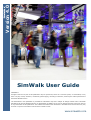
SimWalk User Guide
COPYRIGHT
All rights reserved. No part of this publication may be reproduced, stored in a retrieval system, or transmitted, in any
form or by any means, electronic, mechanical, photocopying, recording or otherwise, without prior written permission of
Savannah Simulations AG.
The information in this publication is provided for information only and is subject to change without notice. Savannah
Simulations AG and its affiliates assume no responsibility or liability for any loss or damage that may arise from the use
of any information in this publication. The software described in this document is furnished under License and may only
be used or copied in accordance with the terms of that License.
www.simwalk.com
ABSTRACT
This Quick Start Guide shows in a short overview how to run the demo projects included
in SimWalk Demo and how to view and analyse the simulation results.
This Quick Start Guide is intended to lead the user quickly into the main functionalities
and possibilities of SimWalk Pedestrian Simulation. For more detailed information see the
SimWalk User Guide.
ote: If you first want to get an overview of the simulation data in the demo project and
see the powerful features of SimWalk you can go to chapter 2 and view the demo movie.
1. Run the demo project
1
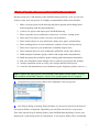
After a successful setup, start SimWalk main program by double-clicking the desktop
icon or selecting Start/Programs/SimWalk 4.0.
2
The main window opens and the program copyright and version info are shown.
2
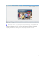
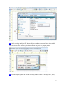
3
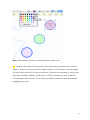
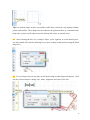
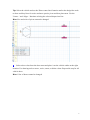
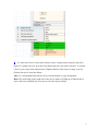
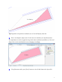
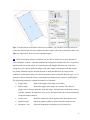
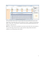
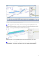
The Display window opens, showing the architectural drawing. On the right side, the
Legend panel displays two levels, 'Concourse' and 'Station' and additional information
regarding the architecture (drawing name, width, height, and number of levels).
3
Hint: If you don't like the small blue icons (introduced in version 4.0), just rename the
'Icons' directory in the SimWalk data folder (e.g. 'Icons_off').
4
Press the [Info] button to get more information about the active level.
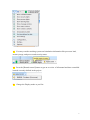
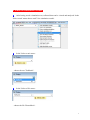
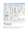
5
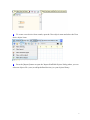
In the 'Select a task' menu choose the task 'Run a new simulation'.
4
ote: Some items may be disabled depending on the features of your license.
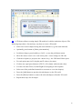
6
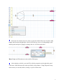
The Display and Simulation windows open.
7
In the 'Select a mode' menu of the Display, choose 'Display mode'.
8
Press the [Start] button to run the simulation.
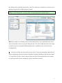
9
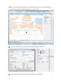
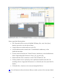
SimWalk starts the simulation process. After creating the levels, objects, and agents
and building the potential fields, Simulation and Display windows allow choosing different
display modes and levels on two independent screens.
Tip: If you have a dual-head video card and a second monitor, you may draw the
Simulation window on the second monitor (if enabled in the Options).
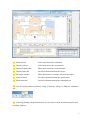
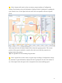
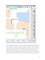
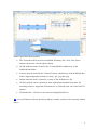
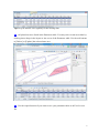
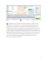
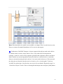
5
A Main tool bar
- Select and control the simulation
B
Display tool bar
- Select and control the presentation
C
Display legend panel
- Show and control the visual elements
D Display status bar
- Provide information about the layout
E
Messages window
- Show information, warnings, and error messages
F
Status window
- Provide information about the agents status
G Main status bar
- Provide information about the simulation run
A1 Use the control buttons to [Pause], [Step], [Continue], [Stop], or [Skip] the simulation
run.
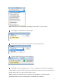
A2 Selecting [Settings] drop-down button, you can show or hide information panels and
auxiliary windows.
6
A3 You may consider tracking system and simulation information like processor load,
memory usage, and process and security status.
A4 Press the [Hazard control] button to get an overview of all manual and time controlled
hazards currently defined in the project.
B1 Change the Display mode as you like.
7
Hint: Some items may be disabled depending on the settings in the Configuration.
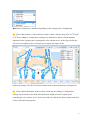
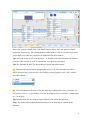
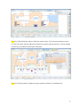
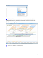
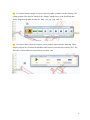
B2 Select 'Max density' or 'Mean density' mode to show a density map (P/m2, m2/P, P/yd2,
or ft2/P) according to Configuration settings. Pay attention to density cell information,
displayed in the Legend panel, regarding the color scheme in use. In the figure below the
cell color corresponds to the current density in agents per square meter.
Select any density cell with a left mouse button click to show the density cell properties.
B3 Select 'Spatial utilisation' mode to show a load map according to Configuration
settings. Pay attention to the load cell information, displayed in the Legend panel,
regarding the color scheme in use. Select any load cell with the left mouse button and click
to show the load cell properties.
8
Select any load cell with a left mouse button click to show the load cell properties.
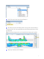
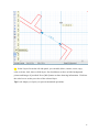
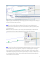
B4 Select 'Speed loss' mode to show a speed map according to Configuration settings.
Pay attention to the speed loss information, displayed in the Legend panel, regarding the
color scheme in use. In the figure below the cell color corresponds to the percental speed
loss in relation to the desired agents walking speed.
Select any speed cell with a left mouse button click to show the speed cell properties.
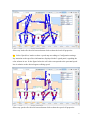
9
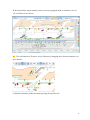
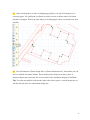
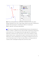
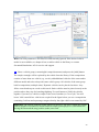
B5 Select 'Agents trails' mode to show a trajectory map according to Configuration
settings. Pay attention to the trail information, displayed in the Legend panel, regarding the
color scheme in use. In the figure below the trail color corresponds to the last waypoint
(Exit).
Select any trail with a left mouse button click to show the agent properties. The current
position of the agent is marked by a small yellow hair cross while the properties are
updated in the info window.
Tip: See appendix D for the meaning of agent status.
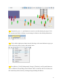
B6 Select 'Agents flow' mode to show an agents map according to Configuration settings.
Pay attention to agent information, displayed in the Legend panel, for the color scheme in
use. In the figure below the agent color corresponds to the current walking speed.
10
Select any agent or vehicle with a left mouse button click to show the agent or vehicle
properties, respectively. The current position of the agent or vehicle is marked by a small
yellow hair cross while the properties are updated in the info window.
Tip: Select the menu item 'Locate position...' or double-click somewhere into the Display
to locate either a point by its X/Y-coordinates or an agent by its number.
Tip: See appendix D and E for the meaning of agent and vehicle status.
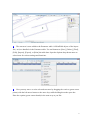
B7 Display tool bar also allows changing the active level. The selected level will be
shown and activated. Only the active level allows selecting agents, trails, cells, vehicles
and other objects.
B8 Use tool buttons to [Zoom] or [Fit] the drawing or change the view to [Isometric] or
[Perspective]. Use [+/–] spin buttons to set the drawing zoom (in %) and the viewing angle
(in °) as desired.
Tip: Double-click into the zoom or angle indicator will restore the last value.
ote: The zoom will be adjusted automatically to fit the drawing (if enabled in the
Options).
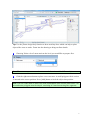
11
In the figure below agent symbols (some accessory equipped) with an isometric view of
30° to both levels are shown.
B9 Use tool buttons to [Zoom to area] of interest by dragging the left mouse button to see
more details,
or [Measure distance] within the drawing using the tapeline tool.
12
B10 Alternatively, use [+/–] spin buttons to zoom in or out the drawing by steps of 10%.
The current zoom factor is shown as a percentage in relation to the drawing dimensions.
B11 Click with the right mouse button into the drawing or the zoom indicator to pop-up a
menu with zoom, printer, locator, and options items.
B12 Press [Rulers], [Grid], [Background], [Images], [Timeline], and [Legend] buttons to
show or hide the corresponding visual elements. Show or hide line and area counter(s) in
the counter drop-down menu by selecting the appertaining checkboxes.
13
B13 Use [Chart] button to show or hide the counter chart. Use left mouse button to move
or resize the chart, and the right mouse button to open the pop-up menu for various settings
relevant for presentation and counter allocation.
B14 Use [Timer] button to display run pass number and time of simulation run.
14
B15 Use left mouse button to move or resize the timer and the right mouse button to open
the pop-up menu for various settings relevant for presentation.
B16 Press [Display text] button to enter optional remarks indicated in pictures or movies.
Use left mouse button to move or resize the text label, and the right mouse button to open
the pop-up menu for various settings relevant for presentation.
15
B17 Use tool buttons to [Make snapshot] or [Record video] of the simulation display. The
pictures are saved in the preselected graphic format in the simulation run folder of the
project and can be viewed later or used to make a movie (see chapter 2.21).
ote: Select GIF video format to make movie using the SimWalk Movie Maker and PNG
to make true color AVI/MPEG movies (needs free 3rd-party video utilities).
Remark: The [Record video] button is only available in the Simulation display.
B18 Press [Print] button to make a hardcopy of the currently seen display.
B19 Right-click into the drawing or the zoom indicator to select and setup the desired
printer.
16
C1 The color scheme is shown according to Display mode and Configuration settings for:
•
Agents speed (m/s or ft/s)
•
Speed loss (%)
•
Spatial utilisation (Agents rel. to load reference)
•
Density (P/m2 or P/yd2)
•
Space (m2/P or ft2/P).
C2 Show or hide levels, objects, and agent groups by clicking the appertaining
checkboxes shown in the Display's Legend panel on the right side. The Legend panel can
be set on or off in the Settings drop-down menu or by pressing the [Close legend] button.
17
D1 In the Display status bar, the current level number, drawing dimensions and unit (m or
yd), cursor position, project and level name are shown. The timeline on top is a graphical
representation of the runtime and the estimated duration. The timeline can be set on or off
in the Settings drop-down menu or by pressing the [Close timeline] button. During a
simulation, the timeline pointer indicates the current runtime whereas the scale marking is
adjusted according to the estimated end of the simulation. If Formations are defined, they
18
are shown as orange boxes marking the arrival and departure times (SimWalk Transport
and Airport only). Small circles indicate Hazard events (if defined).
E1 In the Messages window, general information, warnings, status and error messages are
shown. This window can be set on or off in the Settings drop-down menu or by pressing
the [Close messages] button.
Tip: If an error message contains either an X/Y-coordinate or an agent number, you can
double-click the appropriate line to locate that point in the Display.
F1 In the Status window all pending, active, moved, waiting, or done agents as well as
agent groups with the same waypoint and their average speed (m/s or ft/s) are shown.
Right-click into the table to pop-up a menu with aligning, clipboard, export, and table
settings items. This window can be set on or off in the Settings drop-down menu or by
pressing the [Close status] button.
19
G1 In the main Status bar, actual date and time, real time, run pass and time, progress in
% agents done, run pass name and currently used agents plan are shown.
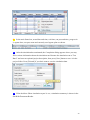
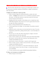
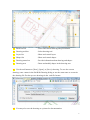
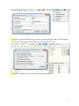
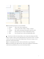
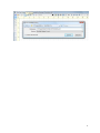
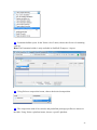
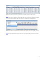
10 After the simulation has terminated, the Completion dialog appears where you may
fill in various information about the simulation run. Rename the simulation run to 'Test
Run 2' and enter an optional project description, then press [Save] button to save it in the
project folder. Press [Discard] if you don't want to save the simulation data.
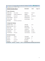
11 If the checkbox 'Show simulation report' is set, a simulation summary is shown in the
SimWalk Document Reader.
20
21
2. View the simulation results
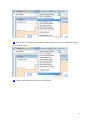
1
After having saved a simulation run, collected data can be viewed and analysed. In the
'Select a task' menu choose task 'View simulation results'.
2
In the 'Select a run' menu...
...choose the run 'TestRun01'.
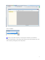
3
In the 'Select a file' menu...
...choose the file 'DemoMovie'.
1
4
The SimWalk Viewer opens and the movie is loading and then playing. Use the
control buttons to [Pause], [Next], [Stop] and [Play] the movie. Use the [Zoom] and
[Speed] buttons to change the presentation.
5
Repeat step 3 and choose file 'Density map'.
2
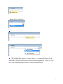
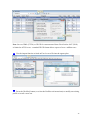
6
In the 'Select a pass' menu choose the pass 'Run pass 1'.
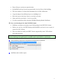
7
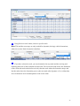
The density map opens in the Display window. You may select actual, maximum, or
mean density mode, enter a time range and then press the [Density map] button to refresh
the density map.
Hint: The data processing may take several seconds before the density map is updated.
8
Repeat step 3 and choose the file 'Database'.
3
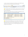
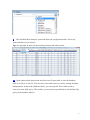
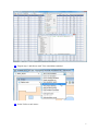
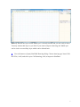
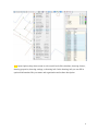
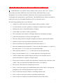
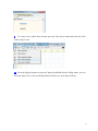
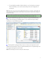
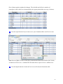
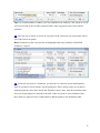
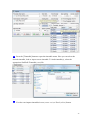
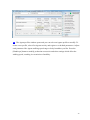
9
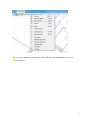
The SimWalk Data Analyser opens and shows the configuration table. Select any
mode and table of your interest.
Tip: See appendix D and E for the meaning of agent and vehicle status.
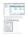
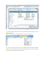
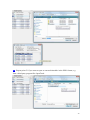
10 Open Options drop-down menu and select item 'Export table' to save the database
table as an Excel or text file. You also may select other items for various settings and data
manipulations. In the mode 'Database tables', you can open the 'Select table' menu to
choose the item 'SQL query'. This enables you to perform a predefined or self-defined SQL
query on the database table(s).
4
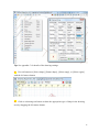
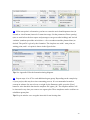
11 Repeat step 1 and choose task 'View simulation statistics'.
12 In the 'Select a run' menu...
5
...choose the run 'TestRun01'.
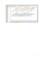
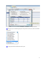
13 In the 'Select a mode' menu...
...choose mode 'Agents speeds'.
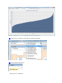
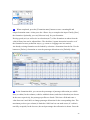
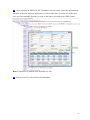
14 The SimWalk Data Analyser opens and shows the 'Agents speeds' chart. Use the
Options drop-down menu for various settings and data manipulations. Repeat step 13 to
show other statistical presentations of the collected simulation data.
6
15 Repeat step 1 and choose task 'Run an existing simulation'.
16 In the 'Select a run' menu...
...choose the run 'TestRun01'.
7
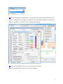
17 Before starting the simulation run, you may open the Settings drop-down menu and
choose 'Configuration' to configure and adapt various simulation parameters of the project.
Tip: See appendix A for details of the Configuration settings.
18 Choose the 'Options' item to set your personal 'look & feel'.
Tip: See appendix B for details of the Options settings.
8
19 Select the desired display mode and press [Start] button to re-run the simulation.
20 Repeat step 1 and choose task 'Replay simulation run'. Then repeat steps 16 to 19 to
run existing simulation pass with the collected data from the database.
9
21 Repeat step 1 and choose task 'Make simulation movie' to join recorded video frames
to a SimWalk movie.
22 Video window opens. In the 'Select a run' menu,
10
choose 'TestRun01'.
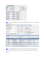
23 Select a video frame in the list to view the picture. If needed, use tool button to
[Delete] selected frame(s). After setting a frame delay time [ms] and entering a name, start
video creation by clicking the [Create video] button.
11
12
3. Prepare your CAD drawing for SimWalk (Full version only)
1
The first and most important task is to prepare your CAD drawing to optimize it for
the requirements of pedestrian simulation with SimWalk. It is highly recommended to
follow this checklist:
I. Simplify your architecture as much as possible:
•
Remove all 'unused' shapes like architectural details (e.g. plants, stair treads,
markers...). Example: Only the trunk of a tree is an obstacle for pedestrians and not
the treetop - it is sufficient to only draw a small circle on the floor for the trunk
instead of a big one for the whole tree.
•
Signaling objects like crosswalks or road markings can be set 'marked' later in the
SimWalk Drawing Board. These objects are not 'seen' by agents and will not affect
the agents flow during a simulation run.
•
Remove all design and dimension lines and auxiliary texts.
•
Close the gaps between line endings - use closed shapes, like polylines, instead of
line pieces.
•
SimWalk is sensitive to lines that are not closed and don't have contact. The reason
being that the potential fields - guiding pedestrians paths - rely on closed shapes for
activation.
•
The best way is to re-draw the outlines using polygons, rectangles, circles and
polylines and delete the older lines afterwards.
•
Open (or remove) all doors, gates, and turnstiles where agents should walk through;
there must be a free flow from start to exit points. Gates and turnstiles will be
simulated with SimWalk objects later.
•
Open all stairs, elevators, and escalators - surround it with U-shaped walls.
•
Remove all stairs, elevators, escalators, tracks, and vehicles - these objects will be
simulated with SimWalk objects later.
•
Stairs, elevators, and escalators have 3 closed walls around and just 1 open side
where the agents can enter or leave (like a U-shape - see also the demo and test
cases in SimWalk).
•
You also can do these tasks using the SimWalk Drawing Board (SimDraw)
II. Merge your drawing layers to building levels:
•
Delete all empty or not used layers.
1
•
Place all layers exactly one upon the other.
•
In SimWalk each layer must correspond with a level (a floor) of the building.
•
The layer number 0 is always the bottommost level of the architecture.
•
Copy the shapes from different layers to a building level.
•
Move the layers in the layer list to re-sort the level order.
•
Name and color your layers = levels as you like.
•
You also can do these tasks using the SimWalk Drawing Board (SimDraw)
III. Save your drawing in the AutoCAD R12 format
•
SimDraw can import (read only) AutoCAD drawings in the DXF R12 format.
•
Before you can use your DXF drawing with SimWalk, you have to save, export, or
convert it to R12 format.
•
This is an older but widely used DXF format, supported by most CAD software
tools and converters.
$ote: The import and saving of CAD drawings is only available in the SimWalk Full
Version. Drawings for import must be available in the AutoCAD R12 (.dxf) format.
2
Start SimDraw program the integrated Drawing Board of SimWalk.
3
SimDraw main window opens.
2
Hint: By default one layer called 'MainLayer' is already created and you are ready to draw.
You may rename this layer as you like. If you want to import a drawing, the 'MainLayer'
can be used as an auxiliary layer which can be deleted later.
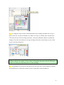
4
Use tool button to [Open] SimWalk Drawing dialog. Choose drawing type 'AutoCAD
R12 File (*.dxf)' and select your CAD drawing (.dxf) to import in SimDraw.
3
5
The 'Import AutoCAD' dialog opens. Select the AutoCAD unit, X/Y-offsets and
percental scaling and rotating options to adjust your drawing after the import.
$ote: It is important to save the DXF drawing with its drawing extensions (AutoCAD
parameter EXTMIN and EXTMAX).
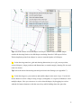
6
Your CAD drawing will be converted to the SimDraw format and shown.
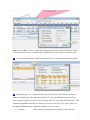
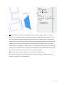
4
A Main tool bar
- Select and control drawing and presentation
B
Drawing tool bar
- Select drawing tool
C
Layers list
- Show and control layers
D Shapes list
- Show and control shapes
E
Drawing status bar
- Provide information about drawing and shapes
F
Drawing area
- Draw and modify shapes in the drawing area
A1 Use the tool buttons to [New], [Open], or [Save] a drawing. To save the current
drawing, enter a name in the SimWalk Drawing dialog or use the same name to overwrite
the drawing file. Do always save drawings in the .swd file format.
A2 You may also save the drawing as a picture for documentation.
5
A3 Use tool buttons to [Zoom] or [Fit] the drawing or change the view to [Isometric] or
[Perspective]. Press [Print] button to view all visible layers in the printer preview. Enter
and adjust header and footer and set print checkboxes as you like. Use buttons to [Setup]
the printer, [Cancel] or [Print] the drawing.
$ote: Saving and printing a drawing is not available in the Demo version. Optional
background pictures will not be printed.
6
A4 You can export a layer of the drawing as a SimWalk layout file (.swl).
A5 You can import an existing layout file (.swl) as a new drawing layer.
7
A6 Click into the layer field to open the layer selection list and then select the active layer
in the pop-up menu.
$ote: You can only draw and modify shapes in the currently active layer.
A7 Use the tool buttons to [Zoom to area] or to [Measure distance] in the drawing. Rightclick into the drawing background or into the zoom indicator to pop-up a menu with zoom,
print, import, export, properties, and settings items.
8
A8 Use menu buttons to set the [Pen width], [Brush style] and [Brush color] of the
selected shape(s).
9
Hint: Notice that the pen color is determined by the layer's color.
A9 Open the [Drawing tools] drop-down menu to perform an operation on the selected
shape(s). This menu also pops up with a right-click into a selected shape or into the shapes
list on the right side panel. Use the tool button to [Undo] the last operation(s). Press [Layer
list], [Point numbers], [Rulers], [Grid lines], or [Grid dots] buttons to show or hide the
corresponding visual elements. Use the [Snap] and [Draw] buttons to make drawing and
dragging shapes easier.
10
A10 Open Options drop-down menu to select useful tools like calculator, drawing cleaner,
drawing properties, drawing settings, or drawing info. In the drawing info you can fill in
optional information like your name and organisation and a short description.
11
A11 Select 'Cleanup drawing' item to open the Cleanup Drawing window. This tool helps
to clean up the drawing by deleting unused or invalid shapes or layers.
A12 Select 'Settings' item to open the Drawing Settings window.
12
Tip: See appendix C for details of the drawing settings.
B1 Use tool buttons to [Select shape], [Rotate shape], [Select range], or [Select region]
with the left mouse button.
B2 Click on a drawing tool button to draw the appropriate type of shape in the drawing
area by dragging the left mouse button.
13
Tip: Use marked shapes to draw crosswalks, traffic lanes, rail tracks, stop signals, holding
points, and suchlike. These shapes do not influence the pedestrian flow in a simulation but
helps later to place and fit objects into the drawing like tracks or transfer areas.
B3 After selecting the line, arc, rectangle, ellipse, circle, segment, or sector drawing tool,
you may double-click into the drawing area to place a shape at that position using the Draw
shape tool.
B4 You can [Insert text] at any place inside the drawing to label shapes and objects. Click
into the selected shape to change size, frame, alignment, and color of the text.
14
B5 Use [Insert bitmap image] to import external graphic symbols into the drawing. All
bitmap graphic files must be found in the '\Images' subdirectory of the SimWalk data
folder. Supported graphic formats are .bmp, .gif, .jpg, .png, and .ico.
B6 Use [Insert library object] to import vector graphic objects into the drawing. These
drawing objects are created with SimDraw and stored in external object library files. The
file name of object libraries must always end with .swo.
15
B7 After selecting three or more overlapping (poly)lines, you can [Join shape(s)] to a
closed polygon. Use [Add node] or [Remove node] to insert or delete nodes of selected
polyline or polygon. With [Cut open shape] a closed polygon can be converted to an open
polyline.
B8 Use tool buttons to [Draw design line] or [Draw dimension line]. Afterwards you can
move it with the left mouse button. These auxiliary lines help you to draw, place or
measure shapes more precisely but are not visible in the simulation display of SimWalk.
Tip: You also may double-click into the upper side ruler to place a vertical design line or
into the left side ruler for a horizontal design line.
16
C1 In the Layers list on the left side panel, you can add, delete, rename, resort, copy,
color, activate, lock, show or hide layers. Set checkboxes to show or hide background
picture and images if provided. Press [Info] button to show drawing information. Click into
the color box to set the pen color of the selected layer.
Tip: Lock shape(s) or layer(s) to prevent unwanted operations.
17
C2 To change the layer's order click and hold the layer number and then move it up or
down in the list. Use the tool buttons to [Add] a new layer or [Delete] the selected layer.
Click into the layer field to change the name - then press [Rename] button to update the
changes. Press the menu button to [Copy] all shapes from the selected layer to one of the
layers in the drop-down list.
Important: For later use with SimWalk, each layer must conform to a level (floor) of the
building, whereby the number of layers must correspond to the order of levels. The layer
number 0 is always the bottommost level of the building.
D1 Using Shapes list on the left side panel, you can select one or more shapes to modify.
Set checkbox(es) or drop-down menu to lock or unlock the selected shape(s).
18
Tip: Select the 'Delete all invalid shapes in all layers' item to remove hidden shapes
outside the drawing limits or invalid shapes remaining from the CAD import. Select
'Delete duplicate points from shapes' to remove unneeded points of all shapes.
E1 In the drawing status bar, grid and drawing dimensions [m or yd], cursor position,
selected shape(s), shape positions and dimensions (or rotation angle), drawing file size and
name are shown.
Tip: Select the desired measuring unit and precision in the Settings (see appendix C).
F1 In the drawing area, you can draw and modify shapes in the active layer. Use the left
mouse button to select a shape or drag a range (rectangular) or a region (freehand) to select
multiple shapes. Now you can move or resize selected shape(s) by dragging its vertices
with the left mouse button or with the arrow keys while holding down the space bar.
19
Tip: Notice real and relative coordinates (m or ft) in the drawing status bar.
F2 Use the 'Offset shape(s)' tool to move group of shapes to a new position.
Tip: Use the Offset tool and the Drawing settings to optimize your drawing and to fit the
margins around the architecture to about 2m or yd on each side.
F3 Use the 'Scale shape(s)' tool to resize group of shapes to new dimensions.
20
21
4. Draw your own vehicles (SimWalk Transport / Airport)
1
With SimDraw it is possible to draw vehicles (trains, metros, buses, etc.), to place
doors and pivots and to add them to the objects library with model name or type
designation. For a realistic simulation, dimensions, doors and pivot positions must
correspond to the manufacturer's specifications. The SimWalk objects library can either be
built by the user or by Savannah Simulations AG as a customer service.
The following guidelines have to be followed:
•
Outline of a vehicle must be a closed polygon with any number vertices.
•
For inside details, any lines, polylines, rectangles or ellipses may be applied.
•
Drawing line color is black and cannot be changed.
•
Closed shapes can either be filled or patterned.
•
The 4 outermost corner marks of all shapes define the surrounding rectangle.
•
Vehicle driving direction is always from right to left.
•
Doors are always drawn as longish rectangles and must be placed on the outline.
•
Number of doors is not restricted but should not exceed 20.
•
Doors can be drawn by using door menu with cabin classes 0...3.
•
Doors are numbered in the format 'D:C' where D is the door number (1...n) and C is
the cabin class (0...3). Use class 0 for non-classified cabins.
•
Place odd door numbers (1, 3, 5...) on the left side (in driving direction).
•
Place even door numbers (2, 4, 6...) on the right side (in driving direction).
•
Vehicles without doors cannot transport passengers, but can make sense to
represent locomotives, engines or freight wagons.
•
Pivot points are drawn as small circles and must be located on the center line of the
vehicle - they are consecutively numbered from left (1) to right (4).
•
The 4 pivots can be drawn by using the pivot menu.
•
Pivot 1 is the front coupler pivot and headmost point of the vehicle. It assigns the
principal pivot for start/stop positions on respective tracks.
•
Pivot 2 is the front axle pivot which is coinciding with the track.
•
Pivot 3 is the rear axle pivot which is coinciding with the track.
•
Pivot 4 is the rear coupler pivot and the sternmost point of the vehicle.
1
•
It is conceivable and valid that the two left and/or the two right pivots are lying one
upon each other, e.g. if two coupled wagons shares one bogie to build an articulated
vehicle.
•
Reserved object names like 'stair', 'elevator', 'escalator', 'door' or 'pivot' are not
allowed. Do not use a name like an existing vehicle.
•
Vehicle names should only have characters 'A'...'z', numbers '0'...'9', and underline
'_'
•
The default object library is called 'SimWalk.swo' and must be found in the
SimWalk data folder.
•
You can modify and save your objects library as a user-defined file (always with
the ending .swo).
•
You can handle any number of objects libraries, e.g. for each project or customer.
Then in SimWalk you can select the desired library file in the Configuration of
your project.
•
Vehicle parameters can be defined by using the property editor (see below).
Hint: The same way you can create standard objects like trees, furniture, traffic lights and
so on. These objects have neither doors nor pivots, but can also be imported into all types
of SimWalk drawings.
Important: Do not modify, rename, or delete existing objects in the library! Do only work
with your self created vehicles. The objects library file name must end with .swo.
2
Start the SimWalk Drawing Board. Use tool button to [Open] SimWalk Drawing
dialog. Choose drawing type 'SimWalk Objects (*.swo)' and select the objects library
'SimWalk.swo' in the SimWalk data folder.
2
3
Drawing board is opening and library objects are shown on the right side as small
symbols in the objects panel. Click on a symbol and modify vehicle or begin drawing a
new one using the drawing tools on the left side.
Hint: Some drawing functions and tools are not available for objects, whereas the door and
pivot tools and the vehicle properties are solely for vehicle objects.
3
If you have a 3D license, an additional 3D viewer opens showing the 3D model of the
vehicle (if available). Use [3D-view] to show or hide the 3D model.
4
After drawing the vehicle's outline, 4 pivot points must be placed. Select pivots 1 to 4
from the menu and place it on the centerline of the vehicle from left to right. The pivots
represent the vehicles coupler and rotation axis.
4
Tip: Select the vehicle and use the 'Show center lines' function and/or the design line tools
to draw auxiliary lines for easier and more precise pivot and door placement. Use the
'Center...' and 'Align...' functions to bring the selected shapes into line.
Hint: Size and color of pivots cannot be changed.
5
Select a door class from the door menu and place it on the vehicle outline at the right
location. Use drawing tools to move, resize, rotate, or delete a door. Repeat this step for all
vehicle doors.
Hint: Color of doors cannot be changed.
5
6
Select the 'Set vehicle door size' item to open the Vehicle Door tool. Set the width,
height, and elevation (height above floor) of the door(s) in cm or in (depending on the
drawing unit) and press [Apply] to change the size of all selected doors.
Hint: Height and Elevation are only used for 3D objects.
7
After drawing a vehicle, you can fill in vehicle properties on the right side panel.
Click into a field and enter the value specified by the producer. Using Properties dropdown menu you can add, delete, cleanup, or preset vehicle data.
6
Hint: The following parameters are used in SimWalk:
8
•
Producer
Name of the vehicles manufacturer
•
Type
Vehicle type like 'Bus', 'Railcar', 'Wagon', or 'Engine'
•
Capacity
Max. number of passengers having place inside the vehicle
•
Speed
Driving velocity (m/s) of the arriving/departing vehicle
•
Delta
De-/Acceleration (m/s2) of the arriving/departing vehicle
To add a new vehicle to the objects library, enter a unique name and press the [Put]
button. To update a vehicle, press the [Put] button but leave the name as before. To rename
a vehicle, just retype name and press the [Update] button. If the name is empty, you can
[Delete] the vehicle from the library.
Tip: Use a meaningful name like the vehicles model number or type designation.
Hint: The small lamp on the right side of the vehicle name will light up to indicate that a
vehicle has been modified but is not yet saved in the objects library.
7
9
To create a new vehicle from scratch, open the 'New object' menu and select the 'New
vehicle object' item.
10 Press the [Import] button to open the 'Import SimWalk Objects' dialog where you can
select an objects file (.swo) to add predefined vehicle(s) to your objects library.
8
11 After selecting an object file, Import Objects windows opens and shows all available
vehicles. Select those vehicles you want to import and press the [Import] button.
12 Use the [Export] button to save the currently loaded vehicle to an object file (.swo).
9
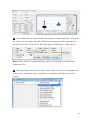
13 A 3D license allows creating simple 3D models of vehicles (and other objects). The
following steps show a fast and easy way how to create a 3D model.
•
Select one or more shapes having the same attributes (e.g. the same material)
•
Optionally press button to [Show point numbers]
•
Lock these shapes (press both keys <Ctrl-L> or use the pull-down menu)
•
Move the mouse cursor over a red corner point - cursor changes to 3D cube
•
Click the red point (or just press the <Insert> key) - the 3D Points Editor opens
•
For each point enter its H- (height) and Z-values (elevation).
•
If values are equal press button to [Fill Z- or H-column with selected value]
•
You also can enter Floor (Z) and Height (H) assigning to all red points
•
Select one of the predefined materials or a texture to cover the shape(s)
•
Press the [Add] button to put the selected shape(s) to the 3D world
•
Press the [Delete] button to remove the selected shape(s) from the 3D world
•
Repeat these steps for all shapes
10
Please regard the following hints:
•
The 3D model will be saved as a SimWalk 3D Binary file (.swb) if the [Save]
button is pressed to save the objects library
•
All 3D models must be located in the '\Virtual\Models' subdirectory of the
SimWalk data folder
•
Textures must be found in the '\Virtual\Textures' subdirectory of the SimWalk data
folder. Supported graphic formats are .bmp, .gif, .jpg, and .png.
•
Define materials in the <materials> section of the 'defaults.swc' file
•
3D-Easy models can be replaced by more sophisticated models from other 3D
modeling software. Supported 3D formats are .x (DirectX) and .3ds (AutoCAD 3D
Studio).
•
3D-Studio files (.3ds) have to be converted using Sim3DS.exe
14 Use tool buttons to [Save] the objects library or make a picture of the currently loaded
object.
11
12
5. Draw your own devices (SimWalk Airport only)
1
With SimDraw it is possible to draw so-called devices and to add them to the objects
library with model name or type designation. Devices are compound objects consisting of
geometric shapes and control objects. They are used to emulate standard terminal facilities
like ticket counters, access and security controls, check-ins, passport controls, boarding
gates, baggage handling, snack bars, and kiosks and so on. For a realistic simulation, all
dimensions and properties must correspond to the manufacturer's specifications. The
SimWalk objects library can either be built by the user or by Savannah Simulations AG as
a customer service.
The following guidelines show the way of proceeding:
•
Draw the housing of the device using standard shapes like lines and rectangles.
•
For construction details (e.g. railings or swing panels), any lines, polylines,
rectangles or ellipses may be applied.
•
Drawing line color is black and cannot be changed.
•
Closed shapes can either be filled or patterned.
•
Place any number of control objects (max. 9 of the same type) and fit them into
place.
•
Define the object's properties which control the device behavior (e.g. pedestrian
throughput rate or queue length).
•
Draw optional hidden lines (invisible guiding elements) to control the pedestrian
flow.
•
Put the device (back) into the objects library and save it.
•
Reserved object names like 'stair', 'elevator', 'escalator', 'door' or 'pivot' are not
allowed. Do not use a name like an existing object.
•
Device names should only have characters 'A'...'z', numbers '0'...'9', and underline
'_'
•
The default object library is called 'SimWalk.swo' and must be found in the
SimWalk data folder.
•
You can modify and save your objects library as a user-defined file (always with
the ending .swo).
1
•
You can handle any number of objects libraries, e.g. for each project or customer.
Then in SimWalk you can select the desired library file in the Configuration of
your project.
Hint: The same way you can create standard objects like trees, furniture, traffic lights and
so on. These objects do not have control objects, but can also be imported into all types of
SimWalk drawings.
Important: Do not modify, rename, or delete existing objects in the library! Do only work
with your self created devices. The objects library file name must end with .swo.
2
Start the SimWalk Drawing Board. Use tool button to [Open] SimWalk Drawing
dialog. Choose drawing type 'SimWalk Objects (*.swo)' and select the objects library
'SimWalk.swo' in the SimWalk data folder.
3
Drawing board is opening and library objects are shown on the right side as small
symbols in the objects panel. Click on a symbol and modify device or begin drawing a new
one using the drawing tools on the left side.
Hint: The door and pivot tools are solely for vehicle objects.
2
If you have a 3D license, an additional 3D viewer opens showing the 3D model of the
vehicle (if available). Use [3D-view] to show or hide the 3D model.
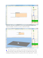
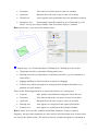
4
After drawing the device's geometry, control objects can be placed. Select an object
from the menu, place it on the device and fit it into place. The figure below shows a selfboarding gate consisting of the device's geometry (ticket console, glass panels...) and two
3
control objects - a delay area (orange) and a turnstile (green). Regard the pass-through
direction of the turnstile indicated by the small arrows.
Tip: Select the design line tools to draw auxiliary lines for easier and more precise object
placement. Use the 'Center...' and 'Align...' functions to bring the selected shapes into line.
Following a short description of currently available control objects:
•
Start area - Locations where pedestrians entering the simulation scenario
•
Exit area - Locations where pedestrians leave the simulation scenario
•
Waiting area - Area where pedestrians are remaining some time, e.g. on a ticket
counter or baggage handling where travelers can check-in or reclaim their baggage.
•
Delay area - Reduce the speed of pedestrians walking in that area, e.g. to emulate a
ramp, a waiting queue, or a man conveyor.
•
Gate - Allow many pedestrians to pass at defined time intervals, e.g. for an access
control or traffic light at pedestrian crossings.
•
Turnstile - Acts as a pedestrian separator, letting through only one pedestrian every
specified service (delay) time, e.g. for a point of payment or a ticket control.
•
Counter - Counts the number of pedestrians passing the line in the defined counting
direction (left-right, right-left, or bidirectional).
•
Meter - Area defined as a simple polygon, counting either the number of
pedestrians inside (load) or the density (P/m2).
5
After placing a control object, you can adjust the object properties on the right side
panel. Click into a given field and select or enter the desired value.
Hint: You are able to modify these parameters later in your simulation model (SimWalk).
4
ote: The property name is predefined and can not be changed. The naming convention is
'XN:Label' where X is the first character of the control object type (e.g. 'T' for 'Turnstile'),
N is a consecutive number from 1 to 9, and ' Label ' is the parameter notation. The row
color is equal to the object's color defined in the Options of SimWalk. You can disable the
table coloring in the Properties drop-down menu (see below).
6
After drawing the device, you can fill in the device properties on the right side panel.
Click into a field and enter the value specified by the producer. Using Properties dropdown menu you can add, delete, cleanup, or preset device parameter.
5
7
To add a new device to the objects library, enter a unique name and press the [Put]
button. To update a device, press the [Put] button but leave the name as before. To rename
a device, just retype name and press the [Update] button. If the name is empty, you can
[Delete] the device from the library.
Tip: Use a meaningful name like the device model number or type designation.
Hint: The small lamp on the right side of the device name will light up to indicate that a
device has been modified but is not yet saved in the objects library.
6
8
To create a new device from scratch, open the 'New object' menu and select the 'New
device object' item.
9
Press the [Import] button to open the 'Import SimWalk Objects' dialog where you can
select an objects file (.swo) to add predefined device(s) to your objects library.
7
10 After selecting an object file, Import Objects windows opens and shows all available
devices. Select those devices you want to import and press the [Import] button.
11 Use the [Export] button to save the currently loaded device to an object file (.swo).
8
12 A 3D license allows creating simple 3D models of devices (and other objects). The
following steps show a fast and easy way how to create a 3D model.
•
Select one or more shapes having the same attributes (e.g. the same material)
•
Optionally press button to [Show point numbers]
•
Lock these shapes (press both keys <Ctrl-L> or use the pull-down menu)
•
Move the mouse cursor over a red corner point - cursor changes to 3D cube
•
Click the red point (or just press the <Insert> key) - the 3D Points Editor opens
•
For each point enter its H- (height) and Z-values (elevation).
•
If values are equal press button to [Fill Z- or H-column with selected value]
•
You also can enter Floor (Z) and Height (H) assigning to all red points
•
Select one of the predefined materials or a texture to cover the shape(s)
•
Press the [Add] button to put the selected shape(s) to the 3D world
•
Press the [Delete] button to remove the selected shape(s) from the 3D world
•
Repeat these steps for all shapes
9
Please regard the following hints:
•
The 3D model will be saved as a SimWalk 3D Binary file (.swb) if the [Save]
button is pressed to save the objects library
•
Control objects are neither used nor seen in 3D
•
All 3D models must be located in the '\Virtual\Models' subdirectory of the
SimWalk data folder
•
Textures must be found in the '\Virtual\Textures' subdirectory of the SimWalk data
folder. Supported graphic formats are .bmp, .gif, .jpg, and .png.
•
Define materials in the <materials> section of the 'defaults.swc' file
•
3D-Easy models can be replaced by more sophisticated models from other 3D
modeling software. Supported 3D formats are .x (DirectX) and .3ds (AutoCAD 3D
Studio).
•
3D-Studio files (.3ds) have to be converted using Sim3DS.exe
13 Use tool buttons to [Save] the objects library or make a picture of the currently loaded
object.
10
11
6. Create your own simulation project (Full version only) F
Having stored your CAD drawing in the SimWalk drawing format (.swd), you are now
ready to create your own project. It is highly recommended to follow this checklist:
1. Make a concept (print out the drawing and plan waypoints and walking routes
before beginning with the implementation).
2. Create a new project and import your SimWalk drawing.
3. Place waypoints in your architecture (start areas, exit areas, waiting areas).
4. Place inter-level objects (stairs, elevators, and escalators).
5. Place control objects in your architecture (delay areas, gates, and turnstiles).
6. Place counting objects in your architecture (counters, load or density meters).
7. Place device objects in your architecture (SimWalk Airport only)
8. Place transport objects in your architecture (platforms, tracks, and vehicles).
9. Build transport formations (group vehicles and assign tracks and platforms).
10. Build the agents plan (schedule agents walking paths and transport timetables).
11. Run your simulation (make multiple runs to optimize your project and settings).
12. Analyse simulation results to verify your concept and find critical areas.
13. Create the documentation of your simulation (report, diagrams, pictures, movies...).
ote: Creating your own projects is not available in the Demo version. Points 7 to 9 are
only available in SimWalk Transport / Airport. Use optional points 4 to 9 if required.
1
Using 'Select a project' menu, choose last command 'Create new project'.
2
New Project dialog is opening. Enter the name of your project and select the desired
unit system (Metric or Imperial). Optionally you can [Select an icon] for your project.
Then click into the Project drawing field to open SimWalk drawing dialog. Choose your
drawing file (.swd) and press the [Create] button. A new project folder will be created and
1
the drawing file is split into layout files (.swl). For each layer (conforms to a level) in your
drawing a layout file in XML format is created.
Important: From now on SimWalk only works with these layout files. If you make
changes in the drawing file (.swd) you have to repeat the project creation (step 1).
Hint: The number of available project creations depends on your purchased license and is
shown in brackets in the new project dialog title bar. The video width determines the image
resolution in pixels of potential fields dumped after a simulation run (if selected in the
Configuration).
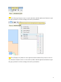
3
If project creation was successful, you can select 'View project drawing' task and level
files are displayed colored as defined in SimDraw. Display handling is described in chapter
1. Using 'Select an object' menu, choose 'Start areas' item. Start areas define where agents
are generated in the layout according to a given simulation scenario.
2
Tip: Use the [Draw design line] function to draw auxiliary lines which can help to place
objects like areas or tracks. Zoom into the drawing to bring out finer details.
4
Choosing 'Select a level' menu activate the level you would like to prepare first.
ote: There are many test cases to demonstrate the functions of the different objects.
5
Click the right mouse button to place a new start area. A small polygon with 4 vertices
is inserted at the cursor position. Press [Add] button to lock the object into position.
ote: The size of the shape is always the same independent of the current zoom factor. All
area and meter polygons must be simple, consisting of 4 non-intersecting line segments.
3
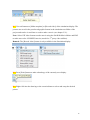
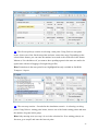
6
The start area is now added to the Parameter table. All SimWalk objects of the layout
file (.swl) are handled via the Parameter table. Use tool buttons to [Save], [Delete], [Find],
[Edit], [Import], [Export], or [Print] the table data. Open the Options drop-down menu to
select items for various settings and functions.
7
Now you may move or resize selected start area by dragging the vertices (green corner
points) with the left mouse button or the arrow keys while holding down the space bar.
Place the caption (green center rhomb) in the same way as you like.
4
Tip: Regard the real position coordinates (m or ft) in the Display status bar.
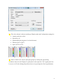
8
Enter a meaningful, unique name for the start area and then press [Update] button.
The right button is used to toggle drawing modes between [Rotate] and [Move]. Color and
shape of the vertices and button icon are changing accordingly.
9
Using Parameter table, press [Save] button to write all table data to the layout file.
5
Tip: Keep in mind to save regularly for not loosing data.
10 All placed areas are listed in the Parameter table. You may select a start area either by
clicking into a shape in the layout or into a row of the Parameter table. Use the tool buttons
to [Delete] or [Update] the selected start area.
11 Use the export function if you want to save your parameter table as an Excel or text
file.
6
ew: Save as XML (UTF-8) or XLSX for vast amount of data. Excel before 2007 (XLS)
is limited to 65'536 rows - extended XLSX format allows export of over a million rows.
12 Use the import function to load an external Excel or text file into the parameter table.
13 Repeat the steps 3 to 13 and select the objects 'Exit areas'. Exit areas are locations
where pedestrians leave the simulation scenario. To get a probabilistic outcome of exit
choices (agents choose the nearest exit) you may label exit areas with identical names. The
simulation algorithm calculates the fastest way to an exit area for every agent. There are
the following parameters to control the behavior of an exit area:
•
Capacity
Max. number of pedestrians having place inside the area
7
•
Frequency
Time interval exit area opens to enter (in seconds)
•
Open time
Duration where the area is open to enter (in seconds)
•
Normal exit
Last waypoint where pedestrians leave the simulation scenario
•
Emergency exit
Exit normally closed but opened in case of a hazard (e.g. fire
alarm - see step 20). Only available if the 'Evacuation' feature is enabled.
Hint: In most cases, you can use the default values.
14 Repeat steps 3 to 12 and select object 'Waiting areas'. Waiting areas are used as
•
Waypoints to define a pedestrian walking path (route)
•
Meeting areas where pedestrians are remaining some time (e.g. in a restaurant or a
ticket office)
•
Baggage handling to check-in and/or reclaim travel baggage
•
Transfer areas where passengers are waiting for their transport formation (e.g. a
platform of a train station).
There are the following parameters to control the behavior of a waiting area:
•
Capacity
Max. number of pedestrians having place inside the area
•
Frequency
Time interval where the area opens to enter (in seconds)
•
Open time
Duration where the area is open to enter (in seconds)
•
Meeting area
Area appears as a waypoint in the Agents plan builder
•
Transfer area
Area appears as a platform in the Formation builder
Hint: Transfer areas are only available in SimWalk Transport / Airport. Capacity,
frequency, and open time parameters are only used for special meeting areas. In most cases
you can use the default values. The effective time (in seconds) the agents are remaining in
8
a waiting area and baggage handling are defined later in the Agents plan builder (see point
37 below).
Tip: You can combine 2 or more waiting areas giving all the same name to model complex
architectures like curved platforms or shapeless geometries.
15 Repeat steps 3 to 12 and select object 'Delay areas'. Delay areas are used to reduce the
speed of pedestrians walking in that area e.g. to simulate a ramp, a waiting queue, or a man
conveyor. You can place delay areas over the architecture. There are some parameters to
control the behavior of a delay area:
•
Speed limit
Max. walking speed of all pedestrians (in cm/s)
•
Speed reduction
Percental speed reduction for each pedestrian (in %)
•
Utilization time
Duration for a pedestrian to transit the area (in seconds)
Hint: The utilization time is always just estimation because of the unknown walking route
of the pedestrians. The walking direction inside the delay area is not relevant.
9
16 For multi-level projects, SimWalk supports inter-level objects like stairs, elevators,
and escalators which allow pedestrians to change from one level to another. Repeat steps 3
to 12 and select objects 'Stairs' (use the same procedure for 'Elevators' and 'Escalators').
Select the next upper and/or lower level where the stair should connect. Then enter a
meaningful unique name and press [Add] button. There are the following parameters to
control the behavior of a stair:
•
Capacity
Max. number of pedestrians having place on the stair
•
Frequency
Time interval the stair is open to enter (in seconds)
•
Speed reduction
Percental speed reduction for each pedestrian (in %)
•
Utilization time
Duration for a pedestrian to transit the stair (in seconds)
Hint: For general purposes you can use the default values.
10
17 Move, resize, and rotate the stair to fit it in the architecture. Repeat steps 16 and 17 to
place and name all stairs on the actual level. Do not forget to save the Parameter table.
Important: An inter-level object should have 3 walls around it, forming a U-shape, and
just 1 open side where the pedestrians can enter or leave. The gap between the object and
the surrounding walls should be in the range of 5..50 cm (2..25 in).
11
18 To place corresponding stairs on other levels, change the active level (point 4), insert
a new stair and select the upper or lower level (point 16). But now, do not enter a new
name but select the name of the corresponding stair found in the drop-down list.
19 To make sure that both stairs are lying exactly upon each other, click 'Align vertical'
checkbox and press the [Add] button, then the stair will be immediately aligned.
12
Tip: To control the movement direction of an escalator, you just have to assign one level
(where the pedestrians can enter) and let the other empty (where the pedestrians come out).
Tip: See Appendix F for the elevator timing diagram.
20 If the 'Evacuation' feature is enabled, you are able to define one or more hazards in
your simulation scenario. A hazard simulates an emergency situation like fire or explosion.
Agents inside the action radius of a hazard realize the danger and run away to the next
emergency exit. Agents inside the danger zone (the orange circle drawn with the mouse)
are greatly influenced by the hazard (injured or dead) and therefore no longer in the
simulation. Hazard activation can either be manual or time controlled. Repeat steps 3 to 12
and select objects 'Hazards'. Enter a meaningful and unique name and press [Add] button.
The following parameters control the behavior of a hazard:
•
Trigger time
Start of the trigger time range (in seconds)
•
End of range
End of the trigger time range (in seconds). The effective
trigger time is chosen randomly from this range. Set both times to the same value to
schedule a hazard. If both times are 0 (zero), the hazard must be activated manually
(using the hazard control).
•
Action zone
Invisible round area where agents realize the hazard (in m)
•
Symbol image
Optional graphic symbol to place elsewhere in the layout
•
Emergency exit
Select the appropriate emergency exit from the list
13
21 SimWalk offers two control objects, 'Gates' and 'Turnstiles', to simulate gate and
turnstile behaviors. Both objects are very similar and both include the option to count
passing pedestrians. A turnstile acts as a pedestrian separator, letting through only one
pedestrian every specified service (delay) time (e.g. for a point of payment, a ticket control,
or a revolving door). On the other hand, a gate has additional 'Open time', 'Offset', and
'Frequency' settings, allowing many pedestrians to pass (e.g. for an access control or traffic
lights at pedestrian crossings). Repeat steps 3 to 12 and select object 'Gates' (use the same
procedure for 'Turnstiles'). Enter a meaningful and unique name and the control times.
Then select the counting and opening direction (left-right, right-left, or both for
bidirectional) and press the [Add] button.
14
Hint: The pass-through direction is indicated by 2 small arrows at the corner points.
During a simulation run, the color of a gate changes with the current state (if enabled in the
Options). Red means the gate is closed and green indicates an opened gate.
Tip: See Appendix G for the gate timing diagram.
22 There are two counting objects with SimWalk that don't interact with pedestrians. A
'Counter' is similar to a turnstile, but only counts the number of pedestrians passing the line
between both vertices. The counting direction (left-right, right-left, or bidirectional) is
indicated by 2 small arrows at the corner points. A meter is an area defined as a simple
polygon with for vertices, counting either the number of pedestrians inside (load) or the
density (P/m2 or P/yd2). Optionally the area color changes according the current level of
service (LoS). Repeat steps 3 to 12 and select objects 'Meters' (use same procedure for
'Counters'). Enter a meaningful and unique name and select the mode.
15
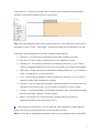
23 Introduced in Version 4.0, SimWalk Airport provides support for device objects.
Devices are compound objects consisting of geometric shapes and control objects. They
are used to emulate standard terminal facilities like ticket counters, access and security
controls, check-ins, passport controls, boarding gates, baggage handling, snack bars, and
kiosks and so on. Devices must be drawn with SimDraw program and are stored in the
objects library (see chapter 5). Repeat steps 3 to 12 and select objects 'Devices'. Select the
desired device model from the list, enter a meaningful and unique name and press [Add]
button. Use the mouse to move the device to bring it in position.
Hint: Devices has a fix size and can not be resized inside the layout.
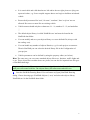
In the figure below you see 5 identical devices, each consisting of a delay area and a
turnstile to emulate a self-boarding gate.
16
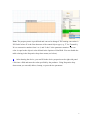
All control objects from a device are also listed in the associated Parameter table. In the
figure below, you see the delay area 'D1' of the device 'GateA1'. It appears in the Parameter
table as 'GateA1*D1'. The asterisk (*) inside the object name indicates that the delay area
belongs to a superior device.
Hint: Device control objects can neither be moved nor resized, hence the corner points are
not green but orange. Only the object's caption position (orange rhomb) and control
parameter (e.g. the delay time) can be altered.
17
Hint: If the desired device model is not available, see chapter 5 how to add a device to the
library or contact Savannah Simulations AG for service and support.
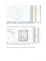
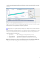
24 Furthermore, SimWalk Transport / Airport supports both objects tracks and vehicles
to emulate trains or metros, trams, busses, taxis, or any other kind of transportation
carriages. A track is a series of line segments (polyline) that a dynamic vehicle can follow.
Static vehicles are not moving and do not need a track (see vehicles below). A track has
always a start and an end point and can have 2 ore more nodes in between. If the start and
the end point are identical, then the track is closed (e.g. for a circular path). Tracks are
'invisible' for pedestrians - therefore they are not seen as an obstacle. Repeat the steps 3 to
12 and select objects 'Tracks'. Enter a meaningful and unique name and press [Add] button.
18
Tip: Design lines and hidden shapes like the light gray tracks in the figure above helps you
to draw and fit objects into your layout.
25 Move nodes with the left mouse button to fit the track in your architecture and
determine where the formation(s) stops. Use the tool buttons to [Insert] or [Delete] nodes,
or [Close] the track.
Hint: The track node numbers are later used by the Formation builder to determine the
stop position and the arriving and departing direction of the vehicle formation.
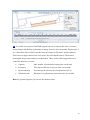
26 A vehicle is an object which can transport agents (passengers). It can act as a start area
(arrival) and/or as an exit area (departure). Vehicles are combined objects consisting of
doors, pivots and a user-defined shape to look like the original. Vehicles must be drawn
with SimDraw program and are stored in the objects library (see chapter 4). Repeat steps 3
to 12 and select objects 'Vehicles'. Select vehicle model from the list and set capacity as
well as number of seats as desired.
19
Hint: The seats parameter is for future use and currently ignored. If the desired vehicle
model is not available, see chapter 4 how to add a vehicle to the library or contact
Savannah Simulations AG for service and support.
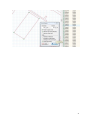
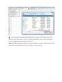
27 Enter a vehicle group (a meaningful composition name) and press the [Add] button.
The simple rectangle will be replaced by the vehicle from the library. If the composition
consists of more than one vehicle (e.g. a train), add additional vehicles of the same and/or
different model and select always the same vehicle group. All vehicles of the same group
build a composition (multiple units). Dynamic vehicles can be placed elsewhere - they
follow a track and stop at a node on this track. Static vehicles must be placed exactly at the
position where they stop for boarding/alighting. Use tool button to [Link] the vehicles
together if you move a vehicle's coupler in the near of another (ca. 1m or yd). You will
hear a 'click' sound if two vehicles are coupled. In the figure below you see a composition
containing 2 railcars and a passenger wagon whereby the right vehicle was rotated by 180°.
Important: The placing sequence of the vehicles is decisive. The first is called the leading
vehicle (engine or locomotive) which foremost coupler (principal pivot 1) determines the
driving direction and the stop position (node) on a track.
20
28 The stop position of the leading vehicle and the composition length must correlate
with the track stop node and the transfer area (platform). Each door should be opposite the
platform. Repeat step 14 and readjust the transfer areas if needed.
Tip: Press button to [Overlay] hidden objects like transfer areas, tracks, and nodes.
29 After the successful definition of platforms, tracks, and vehicles, you are ready to
build formations. Using 'Select a task' menu, choose task 'Build transport formations'.
21
30 Formation builder opens. In the 'Select a level' menu, choose the first level containing
vehicles.
Hint: The Formation builder is only available in SimWalk Transport / Airport.
31 Using 'Select a composition' menu, choose the desired composition.
32 The composition with all its vehicles and predefined passenger profiles are shown in
the table. Using 'Select a platform' menu, choose a specific platform.
22
33 Using 'Select a track' menu, choose a specific track.
Hint: This and the next steps are only needed for dynamic (driving) vehicle formations;
otherwise set the 'Static formation' checkbox.
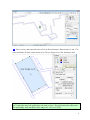
34 If you have selected a track, you can determine the stop node and the arriving and
departing direction of the formation on this track. First select the node where the formation
comes from (the track node before arrival), then the node where the formation stops, and
last the node where the formation goes to (the next node after departure). It is evident that
for a terminus the arrival and departure node are the same.
23
35
When completed, press the [Formation name] button to enter a meaningful and
unique formation name. At last press the <Enter> key to complete the input. Finally [Save]
the formation. Optionally you can [Select an icon] for your formation.
Driving speed (m/s) as well as de-/acceleration (m/s2) of the formation are taken from the
vehicle library but can be adjusted here. The checkbox 'Agents interaction' must be set if
the formation crosses pedestrian ways (e.g. a tram or a baggage cart in a station).
An already existing formation can be loaded by selection a formation from the list. Use the
buttons to [Delete] a formation or reset the passenger allocation to its [Default] values.
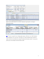
36 In the formation table, you can set the percentage of passenger allocation per vehicle
door (or cabin). In the columns, vehicles with their doors (and class in brackets) are shown.
In the rows respectively, the passenger profiles are listed. Click into a field and enter a
value between 0 and 100% to change passenger allocation for the corresponding door. The
maximum per door (per column) is limited to 100% but less can make sense (if a cabin is
not fully occupied). In the last row, the total percentage door allocation is shown. Press the
24
[Save] button again to update the changes. The schedule and effective number of
passengers in the vehicles are determined by the Agents plan builder (see step 39 below).
37 Use the export function if you want to save your formation table as an Excel or text
file.
ew: Save as XML (UTF-8) or XLSX for vast amount of data. Excel before 2007 (XLS)
is limited to 65'536 rows - extended XLSX format allows export of over a million rows.
38 Use the import function to load an Excel or text file into the formation table.
25
39 The last step is to build the agents plan. Using 'Select a task' menu, choose task 'Build
agents plan'.
40 Agents plan builder and Parameter table opens.
26
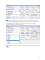
41 The first step always consists in selecting a start point. Using 'Select a start point'
menu, choose one of the listed start points and enter a start time range. Depending on the
selected time format, you can enter the runtime in seconds or the clock time in the format
'hh:mm:ss'. Set checkboxes if you want to show pending agents in the start area and/or let
agents start with travel baggage (if assigned by profile).
Hint: Formations in the start point list are highlighted but only available in SimWalk
Transport / Airport.
42 The next step consists - if needed in the simulation scenario - in selecting a waiting
point. Using 'Select a waiting point' menu, choose one of the listed waiting points and enter
the number of agents in this group.
Hint: Only meeting areas (see step 14) are in the selection list. If no waiting point(s) are
foreseen, go to step 45 and enter the last exit point.
27
43 Enter the waiting time range (in seconds). These values can be equal. Set both to 0
(zero) if the pedestrians should not wait but only pass the waypoint. Set checkboxes if the
waypoint may be used to check-in and/or reclaim travel baggage. Then select the
appropriate agents profile for this agents group.
44 Press [Add] button to add agents to the Parameter table. Repeat steps 41 to 44 for each
waypoint.
28
Tip: It is recommended to conduct your first simulation run with just a few agents to verify
your concept and to check if the potential fields of the waypoints can be built without
problems.
45 The last step is always to select an exit point. In the 'Select an exit point' menu choose
one of the listed exit points.
Hint: Formations in the exit point list are highlighted but only available in SimWalk
Transport / Airport.
46 If the last exit point is a formation, you also have to enter the arrival and departure
time (in seconds or clock format). Set the parameters 'Door closing' (time to wait before
departing after the doors has closed) and 'Departure delay' (max. time the formation waits
if not yet all passengers are aboard) as desired. If the exit point is not a formation, then
these times are ignored. Press [Add] button to add the agents to the Parameter table.
29
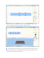
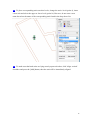
47 If the start point is a formation, you have to enter the arrival and departure time (in
seconds or clock format) instead of a start time range. Set the parameters 'Door opening'
(time to wait before the door opens and passengers can go out after holding) and 'Arrival
variation' (random spread the arrival time ± a few seconds around the planned time) as
desired. The profile is given by the formation. The simplest case with 1 start point, no
waiting point, and 1 exit point is shown in the figure below.
Tip: See Appendix H for the formation timing diagram.
48 Repeat steps 41 to 47 for each additional agent group. Depending on the complexity
of your project, this may be a time consuming process. It is recommended to make a
concept in advance for not to loose oversight. In the Parameter table, press the [Save]
button to write the table data into the template file 'agents_00'. The template number will
be increased every time you create a new agents plan. These templates can be used later to
rebuild an agents plan.
Tip: Keep in mind to save at regular intervals for not loosing data.
30
ew: Press the [O/D] button if you want to display the agents plan as an Origins /
Destinations matrix.
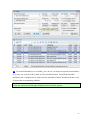
49 To insert a waypoint in an existing agents group, click into a row of the Parameter
table and [Insert] a new row below. The upper row will be duplicated and can then be
edited. After the selected data has changed, [Update] the Parameter table. You may also
[Delete] the selected data from the Parameter table.
31
50 If external timetable(s) are available, you can use it to import waypoints and schedules
in an easy way. Just press the [Start] or [Exit] timetable button. The default timetable
(defined in the Configuration) is loaded into the timetable window. Double-click into a row
to import the corresponding schedule.
ote: Of course the waypoints in your timetable must be available in the start and/or exit
points list, otherwise the message 'Unknown start/exit point' appears.
32
51 Press the [Timetable] button to open the timetable menu. Here you can select the
desired timetable, load or import a new timetable. To load timetable(s), select the
appropriate SimWalk Timetable (.swt) file.
52 You also can import timetables in text (.txt or .csv) or Excel (.xls/x) format.
33
53 Repeat point 51 if you want to open an external timetable in the XML format, e.g.
from a third-party program like OpenTrack.
34
54 After selecting the XML file, the Timetable Converter opens. Select the appertaining
timetable definition and press the button to [Convert] the data. You may also define and
save your own timetable format(s) so long as the data is provided in the XML format.
Hint: Timetables are defined in the 'defaults.swc' file.
55 Repeat point 51 to select the desired timetable.
35
56 After entering all agent routes and saving the Parameter table, you are ready to [Build]
the agents plan.
57 If the plan building process was successful, the generated plan file ('plan_00.swt') is
shown in the parameter table. You are now ready to start a simulation run (see point 64
below).
36
Hint: The number of plan files is limited to 100 ('plan_00.swt' to 'plan_99.swt').
58 If you want to rebuild an existing agents plan, you can select the appropriate template
file (.swa) in the Parameter table (like 'agents_01') and then press [Build] button.
Hint: The number of template files is limited to 100 ('agents_00.swa' to 'agents_99.swa').
59 Use the export function if you want to save your agents plan as an Excel or text file.
37
ew: Save as XML (UTF-8) or XLSX for vast amount of data. Excel before 2007 (XLS)
is limited to 65'536 rows - extended XLSX format allows export of over a million rows.
60 Use the import function to load an Excel or text file into the agents plan.
61 Press the [Profiles] button (or select the Profiles tool menu item) to modify an existing
profile or create a new one.
38
62 The Agent profiles window opens and you can select an Agents profile to modify. To
create a new profile, select first Agents activity and region to set default parameters. Adjust
each parameter like Agents walking speed range or body breadth as you like. Press the
[Handicaps] button to modify pedestrian accessories and other settings which affect the
walking speed, resulting in a restriction of mobility.
39
63 After modifications press the [Profile name] button to rename the profile. At last press
the <Enter> key to complete the input. Finally [Save] the agents profile. Optionally you
can [Select an icon] for your profile. The same applies to handicaps (see figure above).
Hint: Profiles, activities, regions, handicaps, styles, and utilizations are defined in the
'defaults.swc' file.
64 If the agents plan was built successfully, you are able to start your first simulation run.
Using 'Select a task' menu, choose task 'Run a new simulation' and follow the steps in
chapter 1.
40
ote: After modifying any start area, vehicle, formation, or profile, you have to rebuild the
agents plan before starting a new simulation run.
41