1
TrangoLINK-10-EXT™
Wireless Ethernet Bridge
PROFESSIONAL INSTALLATION GUIDE
RU Antenna Alignment
TrangoLINK-10-EXT Professional Installation Guide
Overview
This manual covers basic configuration and installation of the TrangoLINK-10-EXT system which consists of two
radios, P5830S-MU-EXT (Master Unit) and P5830S-RU-EXT (Remote Unit). Since these devices require manual
maximum power limit settings (for 5.25-5.35 GHz U-NII band operation only), they are classified by the FCC as a
professional install devices. To be in compliance with FCC guidelines, the radios must be installed with one of
several approved antennas listed in this document.
The P5830S-MU-EXTR and P5830S-RU-EXT are currently FCC certified for use with three external antennas.
Antenna Part #
Description
Gain
AD5830-24-D
18” DSS Dish
24 dBi
AD5830-23-D
15” Flat Panel
24 dBi
SPD3-5.2
3’ Dish from Radiowaves
31 dBi
The P5830S-MU-EXT Master Unit works in conjunction with the P5830S-RU-EXT Remote Unit. Please see the
TrangoLINK-10 User Manual for general information on overall system implementation, configuration, and
management of these radios. The TrangoLINK-10 User Manual also covers many important aspects of radio
configuration and management which is applicable to the TrangoLINK-10-EXT.
FCC Information
This device complies with Part 15 of FCC Rules and Regulations. Operation is subject to the following two
conditions: (1) This device may not cause harmful interference and (2) this device must accept any interference
received, including interference that may cause undesired operation.
This equipment has been tested and found to comply with the limits for a Class B digital device, pursuant to Part 15
of the FCC Rules. These limits are designed to provide reasonable protection against harmful interference in a
residential installation. This equipment generates, uses, and can radiate radio-frequency energy and, if not installed
and used in accordance with these instructions, may cause harmful interference to radio communications. However,
there is no guarantee that interference will not occur in any particular installation. If this equipment does cause
harmful interference to radio or television reception, which can be determined by turning the equipment off and on,
the user is encouraged to correct the interference by one of more of the following measures:
1) Reorient the antenna;
2) Increase the separation between the affected equipment and the unit;
3) Connect the affected equipment to a power outlet on a different circuit from that which the receiver is
connected to;
4) Consult the dealer and/or experienced radio/TV technician for help.
FCC ID: NCYM5830SSUEXT
Canada: to be announced
IMPORTANT NOTE:
Intentional or unintentional changes or modifications must not be made unless under the express consent of the
party responsible for compliance. Any such modifications could void the user’s authority to operate the equipment
and will void the manufacturer’s warranty. To comply with FCC RF exposure requirements, the following antenna
installation and device operating configurations must be satisfied. The antenna for this unit must be fixed and
mounted on outdoor permanent structures with a separation distance of at least two meters from all persons.
Furthermore, it must not be co-located or operating in conjunction with any other antenna or transmitter.
Warranty Information
Radios from Trango Broadband Wireless are warranted from one year from date of purchase. Please see
www.trangobroadband.com for complete description of warranty coverage and limitations.
Trango Broadband Wireless – Rev. A
Page 2
RU Antenna Alignment
TrangoLINK-10-EXT Professional Installation Guide
General Information
Contents
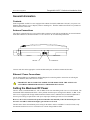
Each TrangoLINK-10-EXT kit comes equipped with a Master Unit (MU) and Remote Unit (RU), two power-overEthernet (PoE) J-Boxes, two AC adapters, and two mounting kits. The MAC Address and Serial # are printed on a
label on the back of the radio.
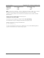
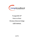
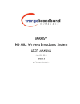
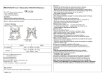
Antenna Connections
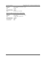
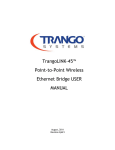
The radio is equipped with two reverse-polarity SMA connectors on the side for attachment to an external antenna.
Each SMA connector is labeled with either “V” for Vertical or “H” for Horizontal polarization.
VERTICAL
HORIZONTAL
Connect each cable to the appropriate vertical and horizontal ports on both the antenna and the radio.
Ethernet / Power Connections
See the TrangoLINK-10 User Manual for detailed diagram for connecting radio to network or PC utilizing the
power over Ethernet (PoE) J-Box and cat-5 cables.
!
IMPORTANT: DO NOT APPLY DC POWER TO THE RADIO UNTIL THE ANTENNA IS
ATTACHED OTHERWISE DAMAGE TO THE RADIO MAY OCCUR.
Setting the Maximum RF Power
The FCC allows a maximum EIRP of 1 watt (30 dBm) for devices transmitting in the 5.25 to 5.35 U-NII band. The
P5830S-MU-EXT and P5830S-RU-EXT’s factory default maximum power setting for this band is +6 dBm. If the
radio is to be equipped with Trango standard antennas AD5830-23-D or AD5830-24-D, no manual adjustment to
the max power setting is required since radio power output plus antenna gain does not exceed 30 dBm.
However, due to FCC restrictions the professional installer must manually reduce the maximum power for
the 5.25 to 5.35 GHz U-NII band if a higher gain antenna is to be used.
The table below shows the maximum power setting for the radio to achieve an EIRP of 1 watt (FCC limit). Only
the antennas listed below are FCC Certified for use with the TrangoLINK-10-EXT.
Trango Broadband Wireless – Rev. A
Page 3
RU Antenna Alignment
Antenna Model
AD5830-23-D
AD5830-24-D
SPD3-5.2
TrangoLINK-10-EXT Professional Installation Guide
Antenna Gain (incl/cable loss)
+24 dBi
+24 dBi
+30 dBi
Radio Max power setting
+6 dBm
+6 dBm
0 dBm
Note: that in all cases, Antenna Gain – cable loss + Radio Max Power Setting is 30 dBm. Once set, the power
leveling feature will still operate normally, but the maximum EIRP will never exceed 1 watt (30 dBm).
The Max Power Setting command is only accessible from the command line and is not available on the HTTP
Browser interface.
The telnet or serial port command to change the maximum power is:
uniimaxpower <max power in dBm>
The flash memory must be updated after running the command. save systemsetting
The command must be run prior to installing the antenna and while the Opmode is OFF.
Example: To set the max power setting for the AD5830-23-D:
#> uniimaxpower 6
#> save systemsetting
Note: The maximum RF power may be left at +22 dBm for the 5.725 to 5.85 GHz ISM band regardless of
which FCC Certified antenna is used. No manual setting is required.
Trango Broadband Wireless – Rev. A
Page 4
RU Antenna Alignment
TrangoLINK-10-EXT Professional Installation Guide
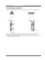
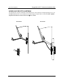
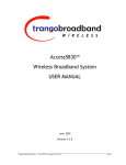
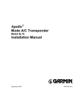
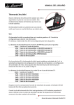
Radio Hardware Installation
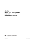
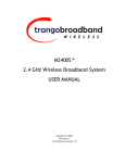
The P5830S-MU-EXT and P5830S-RU-EXT may be installed on a pole or a flat surface per the drawings below:
WALL MOUNTING
POLE MOUNTING
TO ANTENNA
TO ANTENNA
BRACKETS (SUPPLIED)
BOLTS FOR MOUNTING TO WALL
NOT SUPPLIED
Radios should always be mounted with Ethernet and RJ11 ports at the bottom. See the TrangoLINK-10 User
Manual for grounding and additional weatherproofing guidelines. In addition to the guidelines listed in the
TrangoLINK-10 User Manual, installers must cover cable-SMA connectors (both ends) with heat-shrink to provide
weatherproofing of the RF cable connectors.
Trango Broadband Wireless – Rev. A
Page 5
RU Antenna Alignment
TrangoLINK-10-EXT Professional Installation Guide
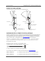
AD5830-24-D DSS STYLE ANTENNA
See diagram below for proper installation of the AD5830-24-D These antennas are designed primarily for low rise
building installations only. Do not install in an area where high (>70 mph) winds are expected. NOTE: Optimal
alignment of this dish (to radio at horizon) is 20° below vertical.
Wall Mount
Trango Broadband Wireless – Rev. A
Pole Mount
Page 6
RU Antenna Alignment
TrangoLINK-10-EXT Professional Installation Guide
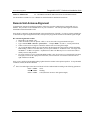
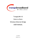
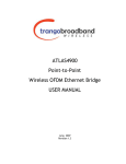
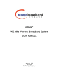
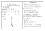
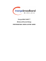
AD5830-23-D PANEL ANTENNA
To install the AD5830-23-D Panel antenna please see the drawing below:
27°
11°
25°
61°
WALL MOUNT BRACKET
POLE MOUNTING
WALL MOUNTING
A-9014
HEAT SHRINK HERE AFTER
TIGHTENING CONNECTOR
2X CA-9023
HEATSHRINK HERE AFTER
TIGHTENING CONNECTOR
POLE MOUNT("V") BRACKET
4X 1) HAND TIGHTEN ALL THREAD INTO ENCLOSURE
2) TORQUE KEP NUTS (8-12 IN-LBS)
3) ATTACH TO POLE WITH "V" BRACKET
4) ATTACH KEP NUTS TO "V" BRACKET AND TORQUE
4X ATTACH WALL BRACKET WITH
5/16-18 X .500 HEX HEAD
AND LOCK WASHERS
HARDWARE TO ATTACH BRACKET
TO WALL NOT SUPPLIED
RADIOWAVES SPD3-5.2 PRIME FOCUS DISH ANTENNAS
The SPD3-5.2 from Radiowaves, Inc. is a parabolic prime focus dish antenna designed for long range applications
and tower installations. These antennas are designed for superior performance in long range applications and
tower installations that may be subject to high winds. Radomes are available from Radiowaves for installations
subject to extreme weather. Contact Radiowaves, Inc. (www.radiowavesinc) for more information.
The SPD3-5.2 is equipped with a standard “N” Female RF Connector interface. A special cable assembly is
required to connect this antenna to the Trango P5830S-SU-EXT’s reverse polarity SMA Female connector.
Recommended Cable Assembly:
REVERSE POLARITY SMA MALE TO STANDARD N MALE
50 OHM, RG142B/U COAX, DOUBLE SHIELDED. Length: 24” – 48”.
Note: To minimize loss, use the shortest cable length possible.
Pre-Assembled Cable Assemblies are available from Pasternack Enterprises www.pasternack.com.
Model No. PE34361-24
24” REVERSE POLARITY SMA MALE TO STANDARD N MALE
Model No. PE34361-36
36” REVERSE POLARITY SMA MALE TO STANDARD N MALE
Trango Broadband Wireless – Rev. A
Page 7
RU Antenna Alignment
Model No. PE34361-48
TrangoLINK-10-EXT Professional Installation Guide
46” REVERSE POLARITY SMA MALE TO STANDARD N MALE
See the Radiowaves SPD3-5.2 User’s Manual for detailed hardware installation instructions.
Remote Unit Antenna Alignment
To align the RU antenna for optimal performance, follow the procedure outlined in the TrangoLINK-10 User
Manual. This procedure is also included below for your convenience. The same procedure applies to both the
P5830S-RU and the P5830S-RU-EXT.
Once the RU’s antenna is mounted and aimed in the general direction of the MU, it is time to perform an RSSI test
to determine the signal strength from the MU, and to precisely align the RU antenna for maximum signal strength.
RU Antenna Alignment Procedure
1. Ensure MU is in opmode “ON”
2. Telnet into the RU (while in opmode “OFF”) or access the radio via hyperterminal/serial port.
3. Type command RSSI <channel> <polarization> - Example RSSI 3 V (chan. 3, vertical polarization)
4. Telnet session screen will begin a continuous readout of the received signal strength.
5. As you read the RSSI reading, move the antenna in the horizontal and vertical planes until the maximum
RSSI reading is achieved. For short links you can expect an RSSI of –60 dBm or better. For longer links
and RSSI of –75 dBm is acceptable. Any RSSI of less than –80 dBm may be too weak for the radios to
reliably associate and pass data.
6. If it is not possible to receive an adequate RSSI reading, it may be necessary to reorient the MU (up/down,
left/right), to increase the output power of the MU, or to move the RU to a location with better line-ofsight conditions to the MU.
Once you are satisfied with the RSSI reading, tighten down the antenna in the optimum position. To stop the RSSI
continuous readout, hit SPACE ENTER.
Note: The amber light on the bottom of the RU will also indicate RSSI according to the following parameters:
not lit
RSSI < -80dBm
RSSI > -80dBm
blinking.
RSSI ≥ -65dBm
solid. (blink rate increases with signal strength.)
Trango Broadband Wireless – Rev. A
Page 8
RU Antenna Alignment
TrangoLINK-10-EXT Professional Installation Guide
Specifications
Radio Transmit Specifications
Frequencies:
Storable Channels:
30 memory locations
Channel spacing: Low Band: 5.260 to 5.340 GHz in 1 MHz channel increments
High Band: 5.736 to 5.836 GHz in 1 MHz channel increments
Default ChannelsChannel 1: 5.736 GHz
Channel 2: 5.756 GHz
Channel 3: 5.776 GHz
Channel 4: 5.796 GHz
Channel 5: 5.816 GHz
Channel 6: 5.836 GHz
Channel 7: 5.260 GHz
Channel 8: 5.280 GHz
Channel 9: 5.300 GHz
Channel 10: 5.320 GHz
Channel 11: 5.340 GHz
Channel 12-30: Un-programmed
Radio RF Conducted Power:
Low Band:
High Band:
EIRP Max:
Max: +6 dBm +/- 2 dB
Min: -8 dBm +/- 2 dB
Max: +22 dBm +/- 2 dB
Min: -8 dBm +/- 2 dB
+52 dBm High band with SPD3-5.2 antenna, +46 dBm with 24 dBi antenna.
+30 dBm Low band Maximum (all antennas)
Freq. Stability:
Freq. Plan:
Modulated BW:
2nd Harmonic atten:
LO Supression:
Symbol Rate:
Error Correction:
Modulation:
.00025 % PLL Stabilized (2.5 ppm) over temp
Single upconversion, 480 MHz IF
22 MHz (null to null, 20 dB)
Per CFR47 part 15.205
Per CFR47 part 15.205
1.375 MSPS
None
1 Mbps DBPSK for header, 11 Mbps CCK spread spectrum for payload
Receiver Section
Cascade Noise Figure:
Sensitivity:
(1E10-6 BER)
Adj. Channel Rejection:
Image Rejection:
Frequency Plan:
LO stability:
< 6 dB
- 83 dBm typical-1600 byte packet
- 87 dBm typical-64 byte packet
> 20 dB for 10 % PER
> 60 dB for 10% PER
Single conversion, IF at 480 MHz
.00025% PLL stabilized (+/-2.5ppm) over temperature range
Data Input Section
Data Rate (User):
Format:
Ethernet packet:
Up to 10 Mbps Sustained throughput
10/100 BaseT IEEE 802.3 Ethernet compliant
Up to 1600 byte long packets
Power
Input Voltage:
Input voltage range at unit is 10.5 VDC to 24 VDC max
Trango Broadband Wireless – Rev. A
Page 9
RU Antenna Alignment
TrangoLINK-10-EXT Professional Installation Guide
Power is supplied on Ethernet cable using junction box provided with up to 330 foot 24 AWG STP cable.
Current Cons.:
575 mA in transmit mode at max power using 20 V standard adapter (11.5W)
500 mA in receive mode using 20 V standard adapter (10 W)
Data Output Section
Data Rate (User):
Format:
Ethernet Protocols:
10 Mbps Maximum sustained throughput
10/100 BaseT IEEE 802.3 Ethernet compliant
TCP/IP, Telnet, TFTP, UDP, HTTP
Physical Interfaces
Serial Interface:
LAN Interface:
Power:
Shielded RJ11 connector
Shielded RJ45 connector
Carried on 4 unused pins of Ethernet cable
Mechanical and Environmental
General Material:
Powdercoated Aluminum base with polycarbonate radome
Size:
12.5”x5”x8” including mounting studs
Weight:
4 lb
Mounting:
Custom mounting bracket with azimuth-elevation adjustment.
Environmental
Operating Temp:
Storage:
NEMA Rating:
-40 to 60 deg C
-40 to 85 deg C
NEMA 4
Standard Power Supply
20 Volt DC Power adapter and J-Box supplied with product.
Type:
Linear wall mount transformer
Input:
120 VAC
Output:
20 VDC +/- 1 V
Max current:
1200 mA
FCC Compliance
Subpart B
Class B Digital device verification
Subpart C
FCC 15.203 Antenna connection requirement – non-standard connection
FCC 15.209 Unwanted emissions below 1GHz FCC 15.207(a) AC conducted emissions 450Khz to 30 MHz
FCC 15.205 Restricted bands (LO and harmonics)= 54 dBuV average @3 meters
EN 301 489-1 Part 7.2
- RF Immunity
AD5830-24-D DSS Style dish for P5830S-SU-EXT
Type
DSS Offset (Satelite TV style) 18" (see drawing)
Polarization
Vertical, horizontal electronically selectable
Frequency
5.2 to 5.9 GHz
Gain
+24 dBi
Azimuth Beamwidth 9 degrees
Elevation Beamwidth 9 degrees
Mount
Standard DSS Style U-Bolt Mount
AD5830-23-D Patch Antenna for P5830S-SU-EXT
Type
Patch - 15" Square
Trango Broadband Wireless – Rev. A
Page 10
RU Antenna Alignment
Polarization
Frequency
Gain
Azimuth Beamwidth
Elevation Beamwidth
Mount
TrangoLINK-10-EXT Professional Installation Guide
Vertical, horizontal electronically selectable
5.2 to 5.9 GHz
+24 dBi
9 degrees
9 degrees
Heavy Duty Universal Mount.
Radio Waves SPD3-5.2 Parabolic Dish for P5830S-SU-EXT
Type
Parabolic Prime Focus 36" Dish
Polarization
Vertical, horizontal electronically selectable
Frequency
5.2 to5.9 GHz
Gain
+31 dBi (30 dBi with Cable Loss)
Azimuth Beamwidth 4.2 degrees
Elevation Beamwidth 4.2 degrees
Cross Polarization
30 dB
Front/Back Ratio
40 dB
Trango Broadband Wireless – Rev. A
Page 11