1
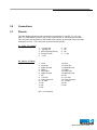
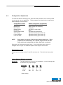
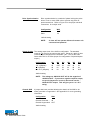
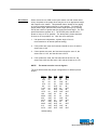
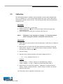
These connections can be grouped into the following categories:
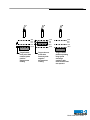
Drive Synchronization - P2 Pins 1, 2, 3, 4, 5, 6, 14, 15, 16, 17, 18, 19:
Drive synchronization is useful when more than one 3800 is being used in a particular
application. Drive synchronization eliminates noise caused by frequency differences
between probe drives. See section 4 for more information.
Power - P2 Pins 8, 9, 10:
Power to the board is supplied by these pins. Power requirements are +15 VDC at
250 mA and -15VDC at 150 mA. Both supplies must be regulated.
Displacement Outputs - P1 Pins 1, 2:
The analog displacement signal is available on these pins. “+ ANALOG OUT” voltage
will increase as distance increases, while “- ANALOG OUT” voltage will decrease as
distance increases.
Limits - P1 Pins 5, 9:
Limit outputs are open collector, TTL-compatible signals representing the state of the
limit LEDs. Refer to section 4.1 for more information.
Noise Immunity (ARTN) - P1 Pin 3:
The ARTN connection may be used to reduce noise due to non-uniform grounds
between the 3800 and any data collection equipment. ARTN is a separate return
which allows external equipment to float +0.1v from analog ground. This allows the
creation of a “pseudodifferential” connection to external monitoring equipment to
prevent ground loops. See Appendix A for more information on grounding.
12
Model 3800 User's Guide