1
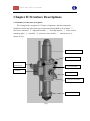
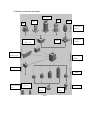
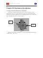
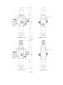
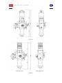
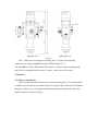
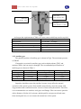
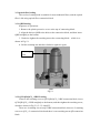
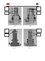
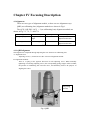
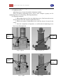
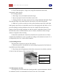
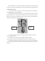
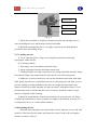
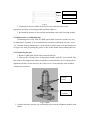
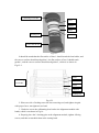
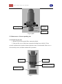
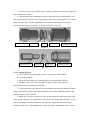
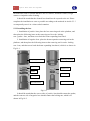
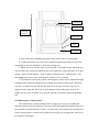
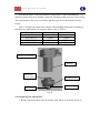
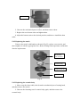
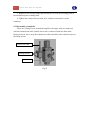
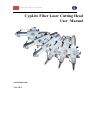
1 CypLite Fiber Laser Cutting Head CypLite Fiber Laser Cutting Head User Manual www.fscut.com Ver 1.5.4 Thank you for using our products! This Manual describes CypLite fiber laser cutting head in details, including installation, operation, installation instructions etc. If you want to know more about BCS100 capacitive height controller that can improve the performance of cutting head while using together, please refer to the help documents of the height controller. For any other information, please contact us directly. Please read the Manual carefully before using the cutting head and relevant devices, so that you can make better use of it in future. Along with continuous updating of product functions, there may be some differences between that you received and the Manual. We will apologize for any inconvenience. 3 CypLite Fiber Laser Cutting Head Contents CHAPTER I PRODUCT DESCRIPTION ........................................................................................ 5 1.1 INTRODUCTION ................................................................................................................ 5 1.2 PERFORMANCE DESCRIPTION .......................................................................................... 5 1.3 TECHNOLOGICAL PARAMETER ......................................................................................... 5 CHAPTER II STRUCTURE DESCRIPTIONS ............................................................................... 7 2.1 SUMMARY OF STRUCTURE DESCRIPTION .............................................................................. 7 2.2 DETAILS OF STRUCTURE DESCRIPTION ................................................................................. 8 CHAPTER III MECHANICAL INSTALLATION ........................................................................... 9 3.1 FIXING AND INSTALLATION DIMENSIONS OF CUTTING HEAD ................................................ 9 3.2 PIPELINE ............................................................................................................................ 12 3.2.1 Water-cooled device ............................................................................................... 12 3.2.2 Auxiliary gas .......................................................................................................... 13 3.3 OPTICAL FIBER LEADING .................................................................................................... 14 3.3.1 QBH leading .......................................................................................................... 14 3.3.2 QCS/QD/QCS_×2/RK Leading ............................................................................. 14 CHAPTER IV FOCUSING DESCRIPTION ................................................................................. 16 4.1 ALIGNMENT ....................................................................................................................... 16 4.1.1 QBH alignment ...................................................................................................... 16 4.1.2 QCS/QD/RK/QCS_×2 alignment .......................................................................... 17 4.2 FOCUS ADJUSTMENT .......................................................................................................... 18 4.2.1 Relationship between focusing lens and focus adjustor ......................................... 18 4.2.2 Relationship between focus and scale .................................................................... 18 4.2.3 Operation of Focus Adjustor .................................................................................. 19 CHAPTER V ROUTINE MAINTENANCE .................................................................................. 20 5.1 MAINTENANCE OF PROTECTIVE LENS ................................................................................ 20 5.1.1 Taking out the lens ................................................................................................. 20 5.1.2 Removing the lens .................................................................................................. 20 5.1.3 Cleaning the lens .................................................................................................... 21 5.1.4 Installing the lens ................................................................................................... 21 5.1.5 Maintenance the lens .............................................................................................. 21 5.1.6 Removing the lens .................................................................................................. 22 5.1.7 Cleaning the lens .................................................................................................... 23 5.1.8 Installing the lens ................................................................................................... 23 5.2 MAINTENANCE OF COLLIMATING LENS .............................................................................. 24 5.2.1 Removing the lens .................................................................................................. 24 5.2.2 Cleaning the lens .................................................................................................... 25 5.2.3 Installing the lens ................................................................................................... 25 5.3 MAINTENANCE OF BEAM EXPANDING LENS ....................................................................... 27 5.3.1 Removing the lens .................................................................................................. 27 5.3.2 Cleaning the lens .................................................................................................... 28 5.3.3 Installing the lens ................................................................................................... 29 5.4 MAINTENANCE OF BOTTOM SUITE ..................................................................................... 30 5.4.1 Replacing the bottom suite ..................................................................................... 31 5.4.2 Replacing the nozzle .............................................................................................. 32 5.4.3 Replacing the ceramic body ................................................................................... 32 5.5 DISASSEMBLY OF AMPLIFIER .............................................................................................. 33 5 CypLite Fiber Laser Cutting Head Chapter I Product Description 1.1 Introduction CypLite is a fiber laser cutting head with lightweight structure and it is designed by Friendess Company. It can be used to cut the stainless steel with a maximum thickness of 5 mm with the best cutting quality and carbon steel with a maximum thickness of 10 mm. The completely sealed optical path can protect optical system from contamination; in the aid of different optical systems, CypLite can be adjusted according to different laser and process requirements; its performance advantages can be given to full play using BCS100 capacitive height controller. 1.2 Performance description High performance price ratio With various options, support plane and three-dimensional cutting Support multiple fiber optic connection ways High temperature resistance and height adjustment without being affected by plasma Convenient focusing module design Precise alignment adjustment module design Quick-detachable protective lens case Optimized smooth air circuit design Compact and lightweight modular mechanical component design 1.3 Technological parameter Cutting Head Max laser power Focal Length Max clear aperture Nozzle aperture Focus adjustable range Horizontal adjustable range Max Assist GAs Weight 2KW 100mm,120mm,150mm,200mm 22mm 0.5mm~2mm -4mm~+6mm ±1 mm 25bar <1.5Kg Other Accessories Collimator lens focal length Fiber laser connector Bottom suites 75mm QBH、QCS、QD、RK、 QCS_×2 2D/3D Cutting Head 7 CypLite Fiber Laser Cutting Head Chapter II Structure Descriptions 2.1 Summary of structure description The cutting head is composed of 7 major components, and the components include the following items from top to bottom by taking QBH as an example: ① fiber laser connector; ② alignment module; ③ focusing module; ④ water-cooled mounting plate; ⑤ amplifier; ⑥ protective lens module; ⑦ bottom suites, as shown in fig.1. ①Fiber laser connector ②Alignment module ④Water-cooled mounting plate ③Focusing module ⑤Amplifier Focusing button ⑥Protective lens module ⑦Bottom suites Fig.1 2.2 Details of structure description QCS_×2 RK QCS QBH QD ①Fiber laser connector QD/RK/QCS /QCS_×2 QBH ②Alignment module ④Water-cooled mounting plate ③Focusing module ⑤Amplifier ⑥ Sleeve Negative lens Lens removal tool ⑦Sensor removal tool 2D 3D Cutting Cutting Fig.2 9 CypLite Fiber Laser Cutting Head Chapter III Mechanical Installation 3.1 Fixing and installation dimensions of cutting head The fixing of cutting head and machine tool are realized using water-cooled mounting plate. There are four M6 fixing holes at the water-cooled mounting plate, and the screws should be tightened at the corresponding position of Z-axis connection block of machine tool, which is as shown in fig.3-1. Four M6 fixing holes Two6mm locating pin Fig.3-1 When the focal length of focusing lens is 150 mm, the mounting dimensions are as shown below.(unit:mm) QBHplan view QBHright view Fig.3-2 QCS plan view QCS right view Fig.3-3 11 CypLite Fiber Laser Cutting Head QCS_×2 plan view QCS_×2 right view Fig.3-4 RK plan view RK right view Fig.3-5 QD plan view QD right view Fig.3-6 Note:When the focal length of focusing lens is 120 mm, the mounting dimensions are changed:QBH286.2mm,QCS286.5mm,QCS_×2 350.7mm,RK302.5mm, QD266.5mm.The distance of water-cooled mounting plate and Nozzle is changed from 163mm to 131mm,other sizes are the same. 3.2 Pipeline 3.2.1 Water-cooled device There are inlet and outlet at the water-cooled mounting plate. It is recommended to enable water-cooled devices when the power is greater than 1,000 watts. In addition, the power of this series of cutting head should not be greater than 2,000 watts. The pipeline structure is shown in Fig.4. 13 CypLite Fiber Laser Cutting Head Water outlet Water inlet Outer diameter: 6mm Outer diameter: 6mm Assist gas Outer diameter: 6 or 8mm Fig.4 As long as the requirements of Table 1 are met, water-cooled loop can be recycled. Min flow rate 1.8 L/min(0.48gpm) Inlet pressure 170-520 kPa(30-60psi) Inlet temperature ≥room temperature /﹥dew point Hardness(compare with CaCO3) ﹤250mg/L PH 6-8 Particle size Diameter﹤200um Table 1 3.2.2 Auxiliary gas The pipeline position of auxiliary gas is shown in Fig.4. The maximum pressure is 25BAR. If impurities are mixed in auxiliary gas, such as hydrocarbons (THC) and moisture (H2O), the lens may be damaged. The recommended specifications of auxiliary gas are shown in Table 2. Gas Purity Oxygen 99.8% Nitrogen 99.998% Argon 99.998% Helium 99.998% Water Content (ppm) THC Content(ppm) ﹤5 ppm ﹤1 ppm ﹤5 ppm ﹤1 ppm ﹤5 ppm ﹤1 ppm ﹤5 ppm ﹤1 ppm Table 2 Impurities should not enter the pipeline, because it may affect the normal operation of the optical system. Non-metallic materials may enter the system with oxygen and moisture and then become a source of dust and hydrocarbons. Therefore, it is recommended to use stainless steel pipes and fittings. Filter can remove particles with a diameter of below 0.01 microns, and the purifier can prevent oil and water from entering the lens, so as to ensure the normal use of the system. 3.3 Optical fiber leading This series of cutting head is suitable for most industrial fibers, and the optical fiber is led using optical fiber connection block. 3.3.1 QBH leading Sequence of operations: 1. Remove the plastic protective cover at the top of connecting block. 2. Align the holes at QBH to the holes at the connection block, and then insert QBH straightly to the bottom. 3. Clockwise tighten the retaining nut on the connecting block,which is as shown in Fig.5-1. 4. Lift the retaining nut and then clockwise tighten it again. Retaining Nut QBH Fig.5-1 3.3.2 QCS/QD/QCS_×2/RK Leading Unscrew the retaining screw at QCS/QD/QCS_×2/RK connection block, insert QCS/QD/QCS_×2/RK straightly to the bottom, and then tighten the retaining screw, which are shown in Fig.5-2, 5-3,5-4 and5-5. There are 4 retaining screws at QCS/RK connection block, there are 2 retaining screws at QCS_×2 connection block and there is one retaining nut at QD connection block. 15 CypLite Fiber Laser Cutting Head Inner Inner diameter: diameter: 14mm 30mm Retaining Retaining screw screw QCS Fig.5-2 QD Fig.5-3 Inner Inner diameter: diameter: 14mm 24mm Retaining Retaining screw screw QCS_×2 Fig.5-4 RK Fig.5-5 Chapter IV Focusing Description 4.1 Alignment There are two types of alignment module, so there are two alignment ways. QBH (no collimating lens) alignment methods are shown in Fig.6. The QCS / QD / RK / QCS_ × 2 (no collimating lens) alignment methods are shown in Fig.7-1, 7-2, 7-3 and 7-4. Type Controlled plant Adjusting screws Focus moving direction QCS/QD/QCS_×2/RK Angle ofincident light 4 Contrary to adjustment direction QBH Collimating lens 2 Same as adjustment direction Table.3 4.1.1 QBH alignment The alignment is completed through adjusting the X-Y direction of collimating lens. A. Alignment tools: Adjusting screws, 2, located at two sides of front of alignment module. B. Alignment methods: There is a spring at the opposite direction of each adjusting screw. When manually tightening or loosening adjusting screws, the corresponding spring stopper will be scalable, the position of collimating lens will also move, and ultimately achieve the purpose of aligning the center. Adjusting screws Fig.6 QBH 17 CypLite Fiber Laser Cutting Head 4.1.2 QCS/QD/RK/QCS_×2 alignment A. Alignment tools: Adjusting screws, located around the alignment module. There are totally 4 adjusting screws, every 2 ones compose a group, one for tightening and one for loosening, matching adjustment. B. Alignment methods: 1. When tightening one of the two adjusting screws, first loosen the screws in the opposite direction, and then tighten this screw. 2. Adjust two groups of adjusting screws, until the beam is located in the center. 3. After the completion of alignment, re-confirm that all adjusting screws have been fully tightened. Adjusting screws Adjusting screws Fig.7-1 QCS Fig.7-2 QCS_×2 Adjusting screws Adjusting screws Fig.7-3 QD Fig.7-4 RK 4.2 Focus adjustment In order to optimize laser cutting process, the cutting head is equipped with a focus adjustor. The position of focusing lens can be moved in focusing module through rotating the knob at the adjustor, so as to achieve the purpose of adjusting focal position, which is as shown in Fig.8. Scale Focus position Locking knob Focusing knob Fig.8 4.2.1 Relationship between focusing lens and focus adjustor The moving range of focusing lens is ―0-10‖ mm. When the scale is adjusted to ―0‖, the lens is located at the top of the focusing module. When the scale is adjusted to ―10‖, the lens is located at the bottom of the focusing module, progressively increasing by taking 1 mm as unit. 4.2.2 Relationship between focus and scale The focus adjustment range is ―-4mm--+6mm‖. For example, when the scale is adjusted to 0, the actual focus is within 4 mm of nozzle tip. When the scale is adjusted to 4, the actual focus is flush with nozzle tip. When the scale is adjusted to 8, the actual focus is outside 4 mm of nozzle tip. scale focus 0 -4 1 -3 2 -2 3 -1 4 5 0 1 Table.4 6 2 7 3 8 4 9 5 10 6 19 CypLite Fiber Laser Cutting Head 4.2.3 Operation of Focus Adjustor 1. Counterclockwise rotate the locking nut and then unlock it. 2. Counterclockwise / clockwise rotate and turn the knob, move the lens position and then adjust the focus. 3. After determining the focal position, clockwise rotate locking nut and then lock it. Chapter V Routine Maintenance 5.1 Maintenance of protective lens Protective lens is located at the bottom of focusing module. When there are impurities or foreign matters at the lens, the lens may be damaged. Therefore, regular maintenance should be conducted for the lens, and it is recommended to clean it once a weak. Please refer to Fig.9 for the lens structure. Protective lenses are wearing parts, and the damaged one should be replaced timely. During maintenance / replacement, workers must wear anti-dust gloves or finger cots, thus preventing the grease or dirt of their hands from polluting the lens. Locking knob Fig.9 5.1.1 Taking out the lens Wear anti-dust gloves / finger cots, press down the locking buttons at two sides of protective lens holder with thumb and forefinger respectively, slowly and steadily pull out the protective lens holder, and then move it to a clean and tidy room. 5.1.2 Removing the lens 1. Place the side with sealing ring down and hold the lens holder with left hand. 2. Gently squeeze the edge of lens using the right thumb from top to bottom (it should be noted to squeeze the edge, because the lens cannot be removed if the middle is squeezed), place the right index finger in the direction opposite to the thumb to protect the lens, so as to prevent the lens from slipping. 3. Continue to gently press the thumb down, until the sealing ring and lens are removed. 21 CypLite Fiber Laser Cutting Head 5.1.3 Cleaning the lens A. Tools: anti-dust gloves / finger cots, long fiber absorbent cotton stick, isopropanol, rubber blower. B. Cleaning methods 1. Wear finger cots at left thumb and index finger. 2. Spray isopropanol onto the absorbent cotton stick. 3. Gently pinch the side edge of protective lens using left thumb and index finger. Note that the finger cots cannot touch the lens surface to avoid leaving marks. 4. Make two eyes direct at the lens, take up the absorbent cotton stick with right hand, gently wipe the lens (it should be noted to avoid wiping back and forth, so as to prevent causing secondary pollution to the lens) in a single direction from top to bottom or from left to right, and then low the lens surface with rubber blower. Clean the both sides, and re-confirm that there are no cleaners, absorbent cotton, foreign matters or impurities after cleaning. It should be noted that the cleaned lens should not be exposed to the air. Please complete the installation as soon as possible according to the methods in Article 5.1.4 or temporarily store it in a clean sealed container. 5.1.4 Installing the lens The both sides of protective lens are flat surfaces. 1. Place the protective lens holder, lens and sealing ring properly from bottom to top and then press them tightly. 2. Press down the locking button at both sides of protective lens holder, and then re-insert it into the bottom of the focusing module. Protective lens holder Protective lens Sealing ring Fig.10 5.1.5 Maintenance the lens Focusing lens is located inside the focusing module, regular maintenance should be conducted, and it is recommended to clean it once one or two months. Before maintenance / replacement operation, workers must wear anti-dust gloves or finger cots, thus preventing the grease or dirt of their hands from polluting the lens. 5.1.6 Removing the lens 1. Wear anti-dust gloves or finger cots, take out the protective lens according to the methods in Fig.11-1 for safekeeping. 2. Remove the short cable, unscrew the 4 screws at the bottom of protective lens module using No.3 hex wrench (there are bayonets at the screw; the screws will not fall down even if they are completely loosened), take out protective lens module and bottom suites, and then place them properly. 2 retaining screws 2 retaining screws Fig.11-1 3. Unlock and adjust the scale to ―10‖, make lens at the bottom of focusing module, and then lock it. 4. Align lens removal tools to the focusing lens holder, and then counterclockwise unscrew the lens holder slowly, which is as shown in Fig11-2. It should be noted that the lens holder can be unscrewed only after the bayonets of tool are aligned to that of lens holder, the installation requirements are the same as the above. 23 CypLite Fiber Laser Cutting Head Focusing module Focusing lens holder Lens removal tool Fig.11-2 5. When the lens holder is completely loosened, slowly and smoothly move it down by holding the tool, and then take out the lens holder. It should be noted that the lens is very light, so please do not shake hands to prevent the lens from falling down. 5.1.7 Cleaning the lens A. Tools: anti-dust gloves / finger cots, long fiber absorbent cotton stick, isopropanol, rubber blower. B. Cleaning methods 1. Wear finger cots at left thumb and index finger. 2. Spray isopropanol onto the absorbent cotton stick. 3. Gently pinch the side edge of protective lens using left thumb and index finger. Note that the finger cots cannot touch the lens surface to avoid leaving marks. 4. Make two eyes direct at the lens, take up the absorbent cotton stick with right hand, gently wipe the lens (it should be noted to avoid wiping back and forth, so as to prevent causing secondary pollution to the lens) in a single direction from top to bottom or from left to right, and then low the lens surface with rubber blower. Clean the both sides, and re-confirm that there are no cleaners, absorbent cotton, foreign matters or impurities after cleaning. It should be noted that the cleaned lens should not be exposed to the air. Please complete the installation as soon as possible according to the methods in Article 5.2.3 or temporarily store it in a clean sealed container. 5.1.8 Installing the lens 1. Place the lens and gasket at the lens holder in order, make the reverse side (flat surface) of lens face the lens holder and front side (convex surface) face the gasket, which is as shown in Fig.12. Gasket Focusing lens Focusing lens holder Fig.12 2. Gently place the lens holder at the special tool, and then place it the appropriate position of focusing module and then tighten it. 3. Re-install the protective lens module and bottom suite at the focusing module. 5.2 Maintenance of collimating lens Collimating lens is only used for QBH optical fiber connector, and the lens can be maintained / replaced. It is recommended to clean the collimating lens once every 3 to 5 months. During maintenance / replacement, workers must wear anti-dust gloves or finger cots, thus preventing the grease or dirt of their hands from polluting the lens. 5.2.1 Removing the lens 1. Remove QBH from optical fiber connection block. 2. Unscrew the 4 fixing screws at alignment module using No.3 hex wrench, and then remove the alignment module (it should be noted that there are 2 locating pins at alignment module, do not miss any one). Move it to a clean and tidy room and then continue the operation. 4 fixing screws Collimating lensholder Fig.13 QBH 3. Counterclockwise unscrew the collimating lens from the alignment module with hands. 25 CypLite Fiber Laser Cutting Head 4. Gently unscrew the locking nut using lens removing tool, and then take out lens and gasket, which is as shown in Fig.14 Locking nut Lens removal tool Gasket 2 Lens 2 Gasket 1 Lens1 Collimating lens holder Fig.14 5.2.2 Cleaning the lens A. Tools: anti-dust gloves / finger cots, absorbent cotton stick, gaseous isopropanol, rubber blower. B. Cleaning methods 1. Wear finger cots at left thumb and index finger, and move the lens holder to a clean and tidy environment after removal. 2. Separate gasket, lens and lens holder with hands in proper order. Spray gaseous isopropanol onto the absorbent cotton stick. 3. Gently pinch the side edge of protective lens using left thumb and index finger. Note that the finger cots cannot touch the lens surface. 4. Make two eyes direct at the lens, take up the absorbent cotton stick with right hand, gently wipe the lens (it should be noted to avoid wiping back and forth, so as to prevent causing secondary pollution to the lens) in a single direction from top to bottom or from left to right, and then low the lens surface with rubber blower. Clean the both sides, and re-confirm that there are no cleaners, absorbent cotton, foreign matters or impurities after cleaning. It should be noted that the cleaned lens should not be exposed to the air. Please complete the installation as soon as possible according to the methods in Article 5.3.3 or temporarily store it in a clean sealed container. 5.2.3 Installing the lens 1. Place the lens removing tool at the platform, wear finger cots, and then place the following items at the removing tool in order: locking nut—gasket 2—lens 2—gasket 1—lens 1, which is as shown in Fig.15-1. Collimating lens holder Lens1 Gasket 1 Lens2 Locking nut Gasket 2 Lens removal tool Fig.15-1 It should be noted that the flat surface of lens 1 should touch the lens holder, and the convex surface should touch gasket 1; the flat surface of lens 2 should touch gasket 1, and the convex surface should touch gasket 2, which is as shown in Fig.15-2. Lens1 Collimating lens holder Gasket 1 Lens2 Gasket 2 Locking nut Fig.15-2 2. Place one side of locking nut at the lens removing tool, and tighten it again with proper force; not tighten it too hard. 3. Clockwise screw the collimating lens back to the alignment module with hands, which is an shown in Fig.16. 4. Properly place the 2 locating pins at the alignment module, tighten 4 fixing screws, and then reassemble them at the cutting head. 27 CypLite Fiber Laser Cutting Head Collimating lens holder 2 locating pins Locking nut Fig.16 QBH 5.3 Maintenance of beam expanding lens 5.3.1 Removing the lens 1. Remove QCS from optical fiber connection block. 2. Unscrew the screw at the beam expansion locking base with No.2.5 hex wrench, and then take down the beam expansion water-cooled module. Move it to a clean and tidy room, and then continue the operations. Jackscrew Locking nut Expanding lens barrel Retaining screw Fig.17 3. Loosen the top screw with No.2 hex wrench, clockwise unscrew the adjusting nut, and then take it down. 4. Unscrew the beam expanding lens barrel from the water-cooled module, and then respectively the positive lens (large, plane-convex lens) and negative lens (small, plane-concave lens) of beam expanding lens with lens removing tool and beam expansion removing tool, which is as shown in Fig.18-1 and 18-2. Lens removal tool Locking nut Gasket Positive lens Expanding lens barrel Fig.18-1 Lens removal tool Locking nut Negative lens Expanding lens barrel Fig.18-2 5.3.2 Cleaning the lens A. Tools: absorbent cotton stick, gaseous isopropanol, rubber blower. B. Cleaning methods 1. Move the lens holder to a clean and tidy environment after removal. 2. Separate gasket, lens and lens holder in proper order. Spray gaseous isopropanol onto the absorbent cotton stick. 3. Gently pinch the side edge of beam expanding lens using left thumb and index finger. Note that the finger cots cannot touch the lens surface. Both the positive and negative lenses can be cleaned. 4. Make two eyes direct at the lens, take up the absorbent cotton stick with right hand, gently wipe the lens (it should be noted to avoid wiping back and forth, so as to prevent causing secondary pollution to the lens) in a single direction from top to bottom or from left to right, and then low the lens surface with rubber blower. Clean 29 CypLite Fiber Laser Cutting Head the both sides, and re-confirm that there are no cleaners, absorbent cotton, foreign matters or impurities after cleaning. It should be noted that the cleaned lens should not be exposed to the air. Please complete the installation as soon as possible according to the methods in Article 5.3.3 or temporarily store it in a clean sealed container. 5.3.3 Installing the lens 1. Installation of positive lens: place the lens removing tool at the platform, and then place the following items at the removing tool in order: locking nut—gasket—lens, and then screw back the beam expanding lens barrel. 2. Installation of negative lens: place the beam expansion removing tool at the platform, and then place the following items at the removing tool in order: locking nut—lens, and then screw back the beam expanding lens barrel, which is as shown in Fig.19-1. Expanding lens barrel Expanding lens barrel Positive lens Negative lens Gasket Locking nut Locking nut Lens removal tool Lens removal tool Fig.19-1 It should be noted that the convex side of positive lens should contact the gasket, and the concave side of negative lens should contact the locking nut, which is as shown in Fig.19-2. Locking nut Negative lens Expandingl ens barrel Positive lens Gasket Locking nut Fig.19-2 3. Screw the beam expanding lens barrel back to the water-cooled module. 4. Counterclockwise screw the beam expansion adjusting nut back to the beam expanding lens barrel, and then re-insert the locking base. 5. When the scale 0 at the water-cooled module is located in front, adjust the top screw at the beam expansion adjusting nut to the right end, ensure that there is no gap among ―water-cooled module – beam expansion adjusting nut - locking base‖, and then tighten the screws at the locking base with No.2.5 hex wrench. 6. The distance between the positive and negative lenses can be adjusted through rotating beam expansion adjusting nut to change the position of the focus. When the top screw is adjusted to the left end, the focus is at the top; when the top screw is adjusted to the right end, the focus is at the bottom. After finding the ideal focus, tighten the top screw with No.2 hex wrench, and then fix beam expansion adjusting nut. 5.4 Maintenance of bottom suite The bottom suite of plane cutting head is composed of 5 parts, including the following items from top to bottom: connector (directly connected with the protective lens module), mechanical part of sensor, ceramic body, and compression nut and laser nozzle. Among them, ceramic body and the laser nozzle are wearing parts, which can be replaced if damaged. 31 CypLite Fiber Laser Cutting Head The bottom suite of 3D cutting head is composed of 3 parts, including the following items from top to bottom: connector, mechanical part of sensor, laser nozzle. The replacement is also very convenient, and the steps are not described in details herein. Note: Configure the connectors with the corresponding dimensions according to the different requirements of customers. Please refer to Table 5. Focusing lens PCX-100-UV PCX-120-UV PCX-150-UV PCX-200-UV Focal Length 100mm 120mm 150mm 200mm Table.5 Connector/size 20mm 38mm 70.5mm 120mm Protective lens module Connector Mechanical part of sensor Compression nut Ceramic body Laser nozzle Fig.20 5.4.1 Replacing the bottom suite 1. Remove the short cable from the bottom suite, which is as shown in Fig.21. Short cable Fig.21 2. Unscrew the mechanical part of sensor, and then remove them. 3. Replace the new bottom suite and tighten them. 4. Adjust the bottom suite to the desired position, and then re-install the short cable. 5.4.2 Replacing the nozzle Unscrew the nozzle with hands as shown in Fig.22, replace a new nozzle, and then retighten it with the appropriate force. Redo floating head capacitance calibration after the replacement. Mechanical part of sensor Ceramic body Compression nut Laser nozzle Fig.22 5.4.3 Replacing the ceramic body 1. Move away the short cable, take down the mechanical part of cutting head, and then remove the nozzle. 2. Unscrew the fastening nut of ceramic body again, and then remove the ceramic body. 33 CypLite Fiber Laser Cutting Head 3. Replace a new ceramic body, and directly face it to the two locating posts at the mechanical part of cutting head. 4. Tighten the compression nut with force, and then reassemble it to the connector. 5.5 Disassembly of amplifier There are 4 fixing screws around the amplifier, the upper ends are connected with the transmission cable, and the lower end is connected with the short cable. During removal, move away the transmission cable and short cable, and then unscrew the fixing screws. Transmission cable 4 fixing screws Short cable Fig.23