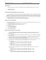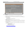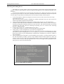
1
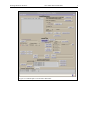
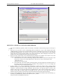
EUROPEAN
.
SOUTHERN OBSERVATORY
.
Organisation Européenne pour des Recherches Astronomiques dans l’Hémisphère Austral
Europäishe Organisation für astronomische Forshung in der südlichen Hemisphäre
.
.
LA SILLA
LA SILLA OBSERVATORY
NEW TECHNOLOGY TELESCOPE
Pointing Model for the NTT
NTT-MAN-ESO-90100-0002
Date: 2001-Oct-10
E.S.O. INTERNAL USE ONLY
Prepared:
Reviewed:
Approved:
Mónica Castillo
Jorge Miranda
Olivier Hainaut
2001 Oct 10
2002 Feb 14
2002 Feb 16
Pointing Model for the NTT
Release
1.0
2.0
Date
1997 Oct 05
2002 Feb 16
NTT-MAN-ESO-90100-0002
2
.
Changes
Original Manual Doc.No. VLT-MAN-XXXX
Complete Revision
Table of Content
1. Introduction
2. Starting the Pointing Modeling Package (Operations).
3. Making a New Pointing Model.
3.1. Check rotator center in database and in the telescope.
3.2. Preparation on TCS.
3.3. Measure the pointing errors.
3.3.1. Automatic Procedure.
3.3.2. Manual Procedure.
3.4. Return TCS to Initial State.
4. Adjusting a Model to the Measured.
5. Installing the Model on the TCS Control System.
6. Fitting a Model to Outdated Pointing Data.
7. How to Test a Previous Model with Newly Taken Data
Page
3
3
3
3
4
6
10
10
10
11
12
12
12
Pointing Model for the NTT
NTT-MAN-ESO-90100-0002
3
.
Introduction
This manual provides a description and operation of the Pointing Model (POM) software for the NTT.
1.1. Relevant Document
TPOINT user manual
Starting the Pointing Modeling Package (Operations)
At the moment there are two ways to make it: Automatic and Manual mode. Using automatic mode is
preferable because it is more easy and fast. Basically automatic mode chooses stars from a chosen catalog and
template file. Template file define regions of the sky where a measurement must be obtained. The template
makes a preset, and then takes a short exposure, calculates the error vectors, moves the star to center of rotator
by offsetting the telescope, store the errors and then move to next star.
Manual mode procedure is practically same than old pointing model.
Making a New Pointing Model
The making of a new pointing model requires several steps, which should be carefully hand led if a good
preset accuracy is required.
To make a pointing model the following steps are to be taken:
1.2. Check rotator center in database and in the telescope.
1.3. Preparation on TCS.
1.4. Measure the pointing errors
1.4.1. Automatic Procedure
1.4.2. Manual Procedure
1.5. Return TCS to Initial State
Rotator Center in Database and Telescope
First, focusing telescope and correct in the best way the mirror aberrations (image analysis, focus).
Mark down on RTD the point was the telescope pointing is required. This must be the center of
rotation of the rotator.
For checking the center of rotation of the rotator presetting to any star, not too bright and setting guide
probe to center field.
Offset it from the center by 20 arcs, and rotate the rotator +/- 180 degrees to move the object around.
Using the drawing tool of RTD to draw a circle following the rotating object makes this task easier.
Estimate the center of rotator and put down a good mark on it.
Write down x and y values from RTD. Make sure that the values of rotator center are the correct ones,
for it, read the values in the database with the command dbRead in wt5tcs xterm (Figure 2.1).
If in A side type:
dbRead "@wt5tcs:Appl_data:TCS:msw:insData.data(tccdNA,refX)"
dbRead "@wt5tcs:Appl_data:TCS:msw:insData.data(tccdNA,refY)"
If in B side type:
dbRead "@wt5tcs:Appl_data:TCS:msw:insData.data(tccdNB,refX)"
dbRead "@wt5tcs:Appl_data:TCS:msw:insData.data(tccdNB,refY)"
If values founded are different than the values to database change it by writing in wt5tcs xterm
If in A side type:
dbWrite "@wt5tcs:Appl_data:TCS:msw:insData.data(tccdNA,refX)" <value>
dbWrite "@wt5tcs:Appl_data:TCS:msw:insData.data(tccdNA,refY)" <value>
If in B side type:
dbWrite "@wt5tcs:Appl_data:TCS:msw:insData.data(tccdNB,refX)" <value>
dbWrite "@wt5tcs:Appl_data:TCS:msw:insData.data(tccdNB,refY)" <value>
Pointing Model for the NTT
NTT-MAN-ESO-90100-0002
4
.
Figure 2.1: Value of Rotator Center in Database.
Preparation on TCS
Before starting the POM measurement process you must do some preparation on TCS:
Send guide probe to the center field position. Use the corresponding button on TCS main panel.
Disable the autoguider in order to avoid guide probe movement. To do this, call ccseiMsg program,
then select: (Figure 2.2):
Environment: wt5tcs
Process: prsControl:
Type: SETUP ,,TEL.AG.GUIDESTAR NONE
To check it, make a preset, the guide probe mustn't move from center field.
3. Shutdown the active optics.
The POM software will by default try to make a ONECAL for each preset. At the NTT, this will
cause a warning Pop Up. To avoid this, [Shutdown] the Active Optics (Figure 2.3). See possible
errors below (Apendix A).
4. Set the delta UT value for the day. In wt5tcs send the command SETDUT to program trkwsControl,
using ccseiMsg.
The value of DUT can be checked by giving the command GETDUT to program xxxtrkControl
on the corresponding tracking LCUs.
xxxtrkControl: alttrkControl for lt5alt
aztrkControl for lt5az
rottrkControl for lt5rb (or lt5ra)
The current value of DUT can be found at:
http://hpiers.obspm.fr/iers/bul/bulb/bulletinb.dat
1.
2.
Pointing Model for the NTT
NTT-MAN-ESO-90100-0002
Figure 2.2: Guideprobe disable.
Figure 2.3: Shutdown Active Optics.
5
.
Pointing Model for the NTT
NTT-MAN-ESO-90100-0002
6
.
Measuring the Pointing Errors
The making of a pointing model is done using the facilities of the pointing model package POM. This
package consists on three programs, which are interfaced through the use of a single GUI (Graphic User
Interface).
Using program pomMeasure does the measuring the pointing errors. Basically the idea is to preset the
telescope to a given object of well know coordinates, and measure the difference between the position
were the object is expected to be and the position were the object actually is after the preset.
1.
2.
3.
4.
5.
6.
To start the programs, and the GUI (Figures 2.5 and 2.6), run on a TCS xterm on wt5tcs the script:
pomguiStart (Figure 2.4).
This will start the three programs; pomMeasure, pomFits, pomInstall. The pom GUI will also be
started, and pomFits program will be initialized.
Click [Load Catalog] and choose catalog from /vltdata/pointing (Figure 2.7). Select Hip-fk5.tcs.
Create the name of the file that will hold the error measurements. This is done by choose 'Auto Name'
and then pressing button labeled [Create File] on the pom GUI. The name should follow the naming
convention for error files (The file containing the pointing errors are created on the following
directory: /vltdata/pointing).
In wt5tcs xterm write: tail –f /vltdata/pointing/<error_file>"
to check points written to error file; a new line will after each measurement.
Click [Load...] is side of Template file (*.tpl) and choose template from
/vlt/INTROOT/NTTTCS/config (Figure 2.8). For a full model, chose pom Template64.tpl. To check
the system, use pom Template5.tpl. In case of emergency (if you have to do a POM measurement
during observations), use pom Template24.tpl. (template name: TemplateN°.tpl, where N°=number of
stars on template)
Check integration time and window size from [Manual Control] panel. To change integration time or
box side for automatic procedure you have to open 'Manual Control' window (Figure 2.9). There you
will have input boxes for window size and integration time. For NTT a good range of integration time
is from 0.1 to 0.3 seconds. The other parameters don’t need to be changed. Then in [file] menu select
[quit], the time will be stored automatically
Figure 2.4: POM Graphic User Interface.
Pointing Model for the NTT
NTT-MAN-ESO-90100-0002
Figure 2.5: POM Graphic User Interface: Man Panel
7
.
Pointing Model for the NTT
NTT-MAN-ESO-90100-0002
Figure 2.6: POM Graphic User Interface: Tpoint output windows
Figure 2.7: Stars Catalog Selection.
8
.
Pointing Model for the NTT
NTT-MAN-ESO-90100-0002
Figure 2.8: Template File Selection.
Figure 2.9: Manual Control Interface.
9
.
Pointing Model for the NTT
NTT-MAN-ESO-90100-0002
10
.
Automatic Procedure
After of the preparation on TCS and POM, we are ready to start the new measurement
automatically.
1.
2.
3.
4.
Click [Start] on GUI panel.
Check the tail, if no data stored, it means system failure. Normally, data are stored, with name,
coordinates, etc; means system work properly.
Don't worry about the error boxes which pop up (see below the description of possible errors in
appendix A)
If everything goes O.K., make a coffee and relax, check telescope behavior and wait till template
finished.
Manual Procedure
If automatic procedure failed, after of the preparation on TCS, we can start the new measurement
manually.
1.
2.
3.
4.
5.
6.
7.
8.
In POM panel click ‘Manual Control’; a panel will pop up
Click ‘Lookup’ and list of star will be shown in list
Click 'Preset' if you are happy for characteristic of first star, if not choose other one.
Center the star in autoguider RTD pressing ‘Center Object’ (normally the center of rotation of the
rotator). If the object happens to be a double star, reject the object. Select a new, pressing ‘Next’.
When the object is properly centered save the measurement using the button ‘Store’. The values
of the reference position of the object and the value of the actual corrected position of the object
will be saved to the file that was create.
Check that the measurement in pom panel or manual control panel increase after each ‘Store’.
Then press ‘Next’
Repeat steps 4 => 5 => 6 => 7 ... until the last star have been visited.
For a good pointing model, the recommended number is 64 objects.
Then close the manual control panel window.
Return TCS to Initial State
After having concluded the measuring of the pointing errors, you should return to the initial state of
the TCS, with the following steps.
1.
Enable guide probe using ccseiMsg (Figure 2.10), select:
Environment: wt5tcs
Process: prsControl:
Type: SETUP,,TEL.AG.GUIDESTAR CATALOG
If you make a preset, the guide probe must be move from center field to the first guide star.
2. Start the active optics. Active Optics panel clicking:
'Engineering Interface…' (Figure 2.3), and click INITAO in Active Optics Engineering panel.
Pointing Model for the NTT
NTT-MAN-ESO-90100-0002
11
.
Figure 2.10: Guideprobe Enable.
ADJUSTING A MODEL TO THE MEASURED ERRORS
This task is handled by pomFits, which is an interface to TPOINT. Then following steps are necessary to
execute:
1. Input the error file name in the corresponding field on POM GUI. Type in the complete data path:
/vltdata/pointing/yy-mm-dd_UT5_NS.dat and then press the LOAD button on pom GUI. If you have just
finished the measurements, you can press “Use current error file” then [Load]. (Check on the TPOINT
output that the error file has been loaded. A list of the measurements will be displayed. If the file is not
found a error will be displayed instead of the measurement list).
2. Select the terms used at NTT, fit the measurements and display the residuals. This is done if one click
with the “PommeFrittes” button. This can be done manually using 2.a and 2.b.
a. Select the term to be used on the fitting, using the select buttons on the GUI. Presently at the
NTT we use: IA IE CA AN AW NPAE TF TX. There are two ways of selecting the term:
- Select term set, or
-Select the term with [Use] on.
b. Press button FIT. This will actually perform the fitting, and will display the calculated values on
the xterm. Check for a low Sky rms & population. They should be 3 arcs or less. Display the
result of the fit. Press the button PLOT a9.
3. If rms is high (>1.”), look for abnormal measurements. Check the residual values, pressing button
RESIDUAL on pom GUI, and look the listing on the xterm. Look for object with very high residuals. This
could be a star that had been wrongly identified. Then the idea is to mask this object out. Fill in the
number of the object on the field, and press the MASK button. Then repeat the fitting like in point 2.
NOTE: if more than one object needs to be masked out, do it one by one. If you enter more than one
number on the entry field, you will mask out all measurements between first and second entry.
4. If sky rms and population is OK, save the model on a file. The file name should be like the following: yymm-dd_UT5_NSmodel.dat, similar to the input file, with “_model”.
Then press button SAVEMOD on the GUI.
Pointing Model for the NTT
NTT-MAN-ESO-90100-0002
12
.
INSTALLING THE MODEL ON THE TCS CONTROL SYSTEM.
The final step is to install the new calculated model on the telescope control system. This is done by
program pomInstall.
1. Fill in entry field labeled Model to install the name of the file containing the model. This is the same name
that was used in step 4 on the model fitting section. Be sure to include the .dat extension. Then press the
button SHOW MODEL in the pom GUI. Please check that the values shown on the GUI are the same
displayed in the xterm after the command FIT.
2. After 'Load Model' and make some presets to check if model is good. Load model will send new pointing
model to LCUs.
3. Verify that the model was correctly propagated to tracking LCUs. To do use CCSEI, send command
GETTERM to program xxxtrkServer on each of the tracking LCUs (xxx is alt, az, ra or rb). They should
return the same values that are shown on pom GUI. Please note that all the terms will have their signs
inverted with respect to what came out from the fitting. This is because TPOINT uses a different
convention on the coordinates than our control system.
4. If the correct values are loaded, check the new model by presetting some bright objects.
5. If pointing is OK, then save the new model as the default model. Pressing [Install Model] on pom GUI
does this. After this the model will be saved on special files on directory /vltdata/config. And they will be
used to load the model when the LCUs are booted, or the side changed, etc.
FITTING A MODEL TO OUTDATED POINTINDG DATA
It is possible, if desired, to remake a model from previously measured pointing data. This maybe useful, if
new terms are to be tried out, or just to recover the error curves for analysis.
All data measures is kept in directory /vltdata/pointing. From the name it should be easy to identify the
date when the data was taken. This is the reason of enforcing the use of the naming convention previously
mentioned. This is also the reason why users must be careful, not to overwrite old data, by using the same
filenames again.
To remake a model proceed exactly as it is done for fitting a model to newly taken data, but use the name
of the file containing the old data as input for the LOAD button.
HOW TO TEST A PREVIOUS MODEL WITH NEWLY TAKEN DATA
It is possible to check how good a previous model fits on newly taken pointing data. This might be useful
in several situations, among them:
1. To check how stable the pointing models are
2. to see which if there are pointing terms which are changing in time
3. to be able to make trend analysis of different terms
The procedure to check an old model with new data is the following, using the pomFits part of pom GUI:
4. Input the file name holding the measured pointing data the press the LOAD button
5. Select the terms to fit with the select buttons. Usually: ie ia ca an aw tx tf npae or [pommesFrittes]
6. Press button FIT, until change is 0. Usually 3 times is enough.
7. Enter FIX in field next to EXEC button. Press EXEC button. This will execute the command FIX.
8. Press button CLIST to check that the select term are fixed.
9. Assign to each of the terms the value they had in the old model. For this enter in the field besides EXEC
the name of the term with the corresponding value. Press the button EXE. For instance: IE 123.32 <press
EXEC button>
10. Press button CLIST to check that all the terms are fixed and having the value that had been assigned.
11. Press button FIT until change is 0. The RMS 7 Sky Population numbers will reflect the quality of the
fitting of the old model with the new data.
12. Press button PLOT a9. The error curves will reflect the residual errors.
If the effect of a single term is to be seen, the following steps can be done using the pom GUI:
13. Deselect the desired term with the corresponding select button.
14. Select the desired term to unfix it
15. Press CLIST to check that the term is not fixed
16. Press FIT. And check the new value for the single term that was unfixed and the new RMS.
17. Pressing the PLOT A9 button will display the error curves. The residuals can be check in the Tpoint
output.
Pointing Model for the NTT
NTT-MAN-ESO-90100-0002
POINTING MODEL TERMS USED AT NTT
Term Name
Term description
Value Range
IE
Index error in elevation
100 - 140
IA
Index error in azimuth
280 – 310
CA
Left-Right collimation error
120 - 150
AN
Azimuth axis misaligment North South
-10 - -13
AW
Azimuth axis misaligment East-West
20 - 25
NPAE
Az/El non-perpendicularity
-16 - -20
TF
Tube Flexure (sine)
10 – 13
TX
Tube Flexure (tangent)
9 – 13
13
.
Pointing Model for the NTT
NTT-MAN-ESO-90100-0002
14
.
Apendix A
Possible errors which you can (and probably will), get are following.
"Image analysis command not permitted." Don't worry about this. You are just not using the active optics.
Procedure will try to apply ONECOR every time for star where it is. Anyway the error vector measurement will be
taken and telescope will continue to next star.
"Cannot start TCCDs." Don't worry. Procedure starts and stops TCCDs by itself. If it cannot take a exposure it
will continue to next one. You don't even have to start camera for procedure. Of course camera status have to be
ONLINE.
"Failed to execute POINOBJ" No worries again. The coordinates of entry are out of the limit and that entry
will be skipped and next one is chosen.
NOTE1:Allways keep the tail open to see which points are really saved. Sometimes GUI gives wrong values to
'#Measures' output window.
NOTE2: if you stop automatic procedure through 'Stop' button agwsControl can stay to state 'AG busy'. Just init
the agws from TCS Status panel and everything will became normal.
NOTE3: if "SETUP,,TEL.AG.GUIDESTAR NONE(CATALOG)" doesn't work from ccseiMsg use the msgSend
to send message. Syntax:
msgSend wt5tcs prsControl SETUP ",,TEL.AG.GUIDESTAR NONE(CATALOG)"
Pointing Model for the NTT
NTT-MAN-ESO-90100-0002
Apendix B
NTT POINTING MODELS EVOLUTION
Figures a and b display the evolution of the models used at the NTT. No significant trend is observed.
Figure a: Evolution of Side A models.
15
.
Pointing Model for the NTT
NTT-MAN-ESO-90100-0002
Figure b: Evolution of Side B models.
__oOo__
16
.