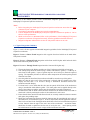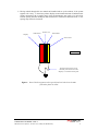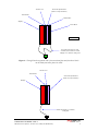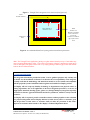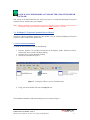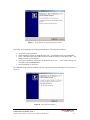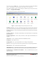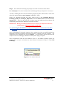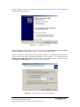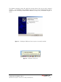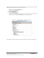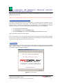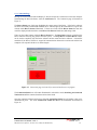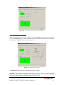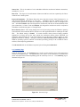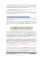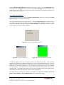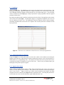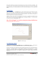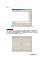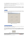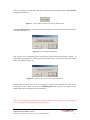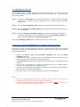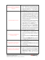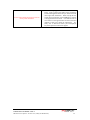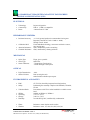
1
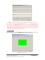
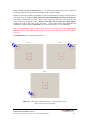
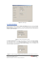
PRO–VU™
TOUCHSCREEN
USER
DRIVER
MANUAL
S O F T W A R E (USB) – F O R W I N D O W S®
Pro Display™ Limited
Units 1 & 2, 2 – 6 Carlton Street Wakefield WF2 8TQ England
Tel: +44 (0)870 766 8438
Fax: +44 (0)870 766 8437
Web: www.prodisplay.co.uk
Email: [email protected]
Touchscreen User Manual – Issue 1
PROVU™ Driver Software Version 1.0.4 (USB) (For Windows®)
1
1.0
CONTENTS
INTRODUCTION
1.1
1.2
1.3
1.4
1.5
1.6
1.7
1.8
1.9
1.10
2.0
About This Manual
Shipping Damage
Care and Cleaning
Unpacking Your Touchscreen
The ProDisplay™ Projected Capacitive Touchscreen
Variants of the ProDisplay™ Projected Capacitive Touchscreen
ProDisplay™ Projected Capacitive Driver Software
Software Compatibility
Before You Begin
Contacting Pro Display™
INSTALLING THE PRODISPLAY™ PROJECTED CAPACITIVE
TOUCHSCREEN
2.1
2.2
Typical Mounting Guidelines
Integration Disclaimer
3.0 INSTALLING THE PRODISPLAY™ PROJECTED CAPACITIVE
DRIVER SOFTWARE
3.1
3.2
3.3
4.0
ProDisplay™ Projected Capacitive Driver Software
Driver Software Installation
Connecting the ProDisplay™ Projected Capacitive Touchscreen to
the Host Computer
CONFIGURING THE PRODISPLAY™ PROJECTED CAPACITIVE
DRIVER SOFTWARE AND TOUCHSCREEN
4.1
4.2
4.3
4.4
4.5
4.6
4.7
4.8
4.9
4.10
4.11
4.12
4.13
4.14
Launching the Touchscreen Control Panel
Contact Page
Connection Page
4.3.1 Connection Page – Advanced
Sensitivity Page
4.4.1 Setting the Sensitivity and Activation Threshold of the Touchscreen
Calibration Page
4.5.1 Launching of the Stand Alone Calibration
Routine using the Calibration.exe Icon
Mouse Page
4.6.1 Double-Click Emulation
4.6.2 Right-Click Emulation
Graph Page
4.7.1 Testing the Touchscreen Integrity
4.7.2 Signal-to-Noise Check
Monitor Page
4.8.1 Monitor Page – Advanced
Edge Gain Page
Help Page
Saving the Control Panel Settings
Storage of the Saved Touchscreen Control Panel Configuration Settings
ProDisplay™ Hot Keys
Process to Uninstall the ProDisplay™ Projected Capacitive
Touchscreen Driver
Touchscreen User Manual – Issue 1
PROVU Driver Software Version 1.0.4 (USB) (For Windows®)
4
4
4
4
4
4
5
5
5
6
6
7
7
10
11
11
11
14
18
18
18
19
20
21
22
23
25
25
26
27
28
28
28
29
29
30
31
31
32
33
34
2
5.0
TROUBLESHOOTING
5.1
6.0
Common Problems and Recommended Solutions
35
35
PRODISPLAY™ PROJECTED CAPACITIVE TECHNICAL
SPECIFICATION (USB)
Touchscreen User Manual – Issue 1
PROVU Driver Software Version 1.0.4 (USB) (For Windows®)
38
3
1.0 INTRODUCTION
1.1 About This Manual
This manual provides all of the information you need to install and use the ProDisplay™ Projected
Capacitive Touchscreen. The manual is organised as follows:
Installation of the ProDisplay™ Projected Capacitive Touchscreen.
Installation of the ProDisplay™ Projected Capacitive Driver Software.
Configuring the ProDisplay™ Projected Capacitive Driver Software and Touchscreen.
Troubleshooting.
ProDisplay™ Projected Capacitive Technical Specification (USB).
1.2 Shipping Damage
On receipt of your ProDisplay™ Projected Capacitive Product, if you notice damage to the shipping
carton, or concealed damage, be sure to save all packing materials for later inspection by the carrier,
who is responsible for any shipping damage.
If failure occurs during the warranty period of the product, please contact the point of sale where the
product was purchased from.
1.3 Care and Cleaning
Handle the touchscreen with care prior and during installation. Do not pull or stress cables and ensure
not to damage the touchscreen prior to installation. Clean the touchscreen surfaces with an alcohol
free glass cleaner and soft cloth. Ensure that the surfaces are clean and dry before integration of the
touchscreen.
1.4 Unpacking Your Touchscreen
Ensure that the following items are present and in good condition:
ProDisplay™ Projected Capacitive Touchscreen, USB Cable, Earthing Cable, Software CD.
1.5 The ProDisplay™ Projected CapacitiveTouchscreen
The ProDisplay™ Projected Capacitive touchscreen is based on Projected Capacitive technology
which enables the device to sense through a protective screen in front of the display. The on board
electronics effectively divide the screen into sensing cells using micro fine wires which are embedded
into a glass laminate construction. These wires are connected to the on board electronic controller
circuitry, and an oscillation frequency is established for each wire. Touching the glass causes a
change in frequency of the wires at that particular point, the position of which is calculated and
identified by the controller and accompanying host Driver software. Unlike other capacitive systems
where the operator touches the actual conducting surface of the sensing panel, the active component of
the ProDisplay™ Projected Capacitive touchscreen is embedded within the glass laminate construction
ensuring long product life and stability.
Touchscreen User Manual – Issue 1
PROVU Driver Software Version 1.0.4 (USB) (For Windows®)
4
The touchscreen can be supplied with options of anti-glare or anti-reflection coatings, thermal
toughening or chemical strengthening and privacy or contrast enhancement filters. The front glass of
the touchscreen acts as a dielectric and enhances the capacitance of the touchscreen.
The ProDisplay™ Projected Capacitive touchscreen is durable and dependable; its construction
protecting against damage caused by moisture, heat, and vandalism.
1.6 Variants of the ProDisplay™ Projected Capacitive Touchscreen
The ProDisplay™ Projected Capacitive USB product has two operation modes depending upon the
application requirement. These two operation modes are:
Direct Touch Application – used for standard applications where an applied touch makes
direct contact with the front surface of the touchscreen.
Through Touch Application – used for through touch applications where the touchscreen
is placed behind a separate front piece of sacrificial glass or polycarbonate.
The above two modes of operation are selectable via the software. The ProDisplay™ USB solution is
powered from the host computer via the USB 5V supply, therefore no external power supply is
required.
1.7 ProDisplay™ Projected Capacitive Driver Software
The ProDisplay™ Projected Capacitive touchscreen is connected to a host computer via a USB lead.
The ProDisplay™ Projected Capacitive Driver software allows the touchscreen to interface with the
host computer’s operating system by emulating the behaviour of a computer “mouse” and translates
applied touches on the touchscreen surface into mouse movement. The type of mouse movement
functionality can be set within the ProDisplay™ Projected Capacitive Driver software.
1.8 Software Compatibility
The ProDisplay™ Projected Capacitive Driver Software Version 1.0.4 (USB) is compatible with the
following Microsoft Operating Systems:
Microsoft® Windows® 98SE (Will operate but no longer supported)
Microsoft® Windows® Me.
(Will operate but no longer supported)
Microsoft® Windows® 2000 (Service Pack 3 and above)
Microsoft® Windows® XP (Home and Professional editions).
Microsoft® Windows® XP Embedded.
Touchscreen User Manual – Issue 1
PROVU Driver Software Version 1.0.4 (USB) (For Windows®)
5
1.9 Before You Begin
Before proceeding with the touchscreen installation ensure the following:
Your Windows operating system is correctly installed and operating with your mouse.
Ensure that all other touchscreen manufactures Driver Software/old touchscreen Driver
software is uninstalled from the host computer to avoid software conflicts.
Ensure that there is a free USB Port available on the host computer to connect the
ProDisplay™ Projected Capacitive touchscreen to.
Ensure that the ProDisplay™ Projected Capacitive touchscreen is NOT connected until the
ProDisplay™ Projected Capacitive Driver Software has been successfully installed first.
1.10 Contacting Pro Display™
Sales and Technical support:
Pro Display USA.
63 Via Pico Plaza
Suite 104
San Clemente, CA 92672
Tel: 1- 800-348-1704
E-mail: [email protected]
Web: http://www.prodisplay.co.uk
Touchscreen User Manual – Issue 1
PROVU Driver Software Version 1.0.4 (USB) (For Windows®)
6
2.0 INSTALLING THE PRODISPLAY™ PROJECTED CAPACITIVE
TOUCHSCREEN
This section of the manual presents several recommended integration guideline scenarios for the
ProDisplay™ Projected Capacitive touchscreen.
Notes:
• Before integrating the ProDisplay™ Projected Capacitive touchscreen ensure that it is NOT
connected to your computer.
• The following integration guidelines are typical recommendations.
• Correct integration of the ProDisplay™ Projected Capacitive touchscreen product is vital to
achieve correct performance.
• Metal work can have a detrimental effect on the performance of the ProDisplay™ Projected
Capacitive touchscreen if integrated incorrectly, therefore guidelines should be followed.
• Integration diagrams outlined in this section are side profiles and are not to scale.
2.1 Typical Integration Guidelines
Figure 1, 2 and 3 all show typical recommended integration guidelines for the ProDisplay™ Projected
Capacitive touchscreen.
Figure 1 illustrates a Direct Touch integration with a typical front bezel which can be made either
from plastic or metal.
Figure 2 illustrates a Through Touch integration with a front sacrificial glass and front bezel which
can be made either from plastic or metal.
Figure 3 illustrates a Through Touch integration with a front sacrificial glass only.
The spacing between the Display and the rear of the Touchscreen should be at least 3mm.
This 3mm spacing should be created using a double sided adhesive gasket (i.e. VHB tape or
some form of foam gasket). Layers of gasket may have to be built up to obtain the required
spacing. The important point here is that even under compression the uniform spacing should
remain at least 3mm.
Once the gasket has been fitted, the touchscreen should be secured on top of the gasket.
Make sure that the active area of the touchscreen is aligned with the viewable area of the
Display and that there is no excessive flexing or mechanical movement between the
touchscreen and the Display.
If a front bezel is to be fitted then this also must be spaced off the front of the touchscreen
using a 3mm double sided adhesive gasket. This 3mm gasket can be applied directly to the
edges of the touchscreen and the spacing must be maintained even under compression.
For metal bezels that are fitted to the front of the touchscreen, the installer must ensure that no
metal work is directly touching the surface of the touchscreen or active area.
Ensure that the front metal bezel and all metal work are correctly earthed to a known common
earth point using earthing straps.
Ideally the front metal bezel aperture should be 10mm greater all round than the active area of
the touchscreen, as illustrated in Figure 4. If this is not possible, then the application software
that is to be executed in the final application should have all critical activation buttons placed
as least 10mm in from the edge of the active area of the touchscreen. Activation buttons
should also be made a significant size for ease of use by the user. Avoid placing critical
activation buttons in extreme corners or edges of the touchscreen active area.
Touchscreen User Manual – Issue 1
PROVU Driver Software Version 1.0.4 (USB) (For Windows®)
7
Having worked through this user manual and installed and set up the software, if the system
appears to be “noisy” i.e. the mouse pointer displays an unwarranted amount of random mouse
pointer movement with no applied touch, then experimentation may need to be carried out
with the spacing between the Display and touchscreen or touchscreen and metal work, i.e. the
spacing may need to be increased.
Display
3mm Gasket
Touchscreen
3mm Gasket
Front Bezel
Side Profile
If a front metal bezel is used,
earth the front metal bezel and
Display to a common earth point
Figure 1: Direct Touch integration with a typical front bezel which can be made
from either plastic or metal
Touchscreen User Manual – Issue 1
PROVU Driver Software Version 1.0.4 (USB) (For Windows®)
8
Touchscreen
Front Sacrificial Panel
(Glass or Polycarbonate)
3mm Gasket
3mm Gasket
Display
Front Bezel
Side Profile
If a front metal bezel is used,
earth the front metal bezel and
Display to a common earth point
Figure 2: Through Touch integration with a front sacrificial glass and front bezel which
can be made from either plastic or metal
Touchscreen
3mm Gasket
Front Sacrificial Panel
(Glass or Polycarbonate)
Display
Earth the Display to common
earth point
Touchscreen User Manual – Issue 1
PROVU Driver Software Version 1.0.4 (USB) (For Windows®)
9
Figure 3: Through Touch integration with a front sacrificial glass only
10mm
invisible boarder
Place buttons in
this active area
Metal front
bezel
10mm
Touchscreen
Boarder separation
between the active
area of the
Touchscreen and the
edges of the metal
work
Figure 4: Recommended Metal bezel spacing and activation button placements
Note: For Through Touch application, placing two glass surfaces directly on top of each other may
cause an optical Newton Ring effect. This can be overcome by selecting a touchscreen construction
with an Anti-glare front glass surface etch or by simply placing a small air gap of less than 0.5mm
between the two affected surfaces.
2.2 Integration Disclaimer
The integration information provided in Section 2.1 is for guidance purposes only and may not
be suitable for the installation of all units. It is therefore the sole responsibility of the integrator
to satisfy itself that the methodology and materials it intends to use are suitable and compatible
with the proposed system of installation and integration and with the Pro Display product.
Pro Display will not accept any liability for damage or degradation of the physical sensor, or
sensing degradation, due to the application of incorrect integration procedures, or the use of
inappropriate materials (bonding agents, gaskets, etc) through third party integration especially
in relation to clearance gaps and metalwork interference parameters, which are clearly stated in
section 2.1.
Pro Display will, if requested, provide reasonable assistance without prejudice in the evaluation
of a proposed integration but Pro Display shall not be liable for any advice or assistance given
and the provision of such advice or assistance shall not affect the provisions of this clause.
Requests for assistance must be made to Pro Display’s Technical Department direct.
Touchscreen User Manual – Issue 1
PROVU Driver Software Version 1.0.4 (USB) (For Windows®)
10
2.0 INSTALLING THE PRODISPLAY™ PROJECTED CAPACITIVE DRIVER
SOFTWARE
This section of the manual describes the step-by-step process to install the ProDisplay™ Projected
Capacitive Driver software onto your computer.
Note: Before installing the ProDisplay™ Projected Capacitive Driver Software ensure that the
ProDisplay™ Projected Capacitive touchscreen is NOT connected to your PC.
3.1 ProDisplay™ Projected Capacitive Driver Software
The Driver software installation described in this manual is for use with the ProDisplay™ Projected
Capacitive USB Communication product only.
3.2 Driver Software Installation
To install the Driver Software carry out the following:
1. Load the Software CD provided and transfer the ProDisplay (USB) Touchscreen Driver
software file onto to your PC Windows desktop.
2. Open the file on your PC Windows desktop.
3. The files are illustrated in Figure 5.
Figure 5: ProDisplay™ Driver software Installation files
4. Using your mouse double click onto the setup.exe icon.
The installation commences with the following screen, as shown in Figure 7.
Touchscreen User Manual – Issue 1
PROVU Driver Software Version 1.0.4 (USB) (For Windows®)
11
Figure 7: Setup Wizard program preparing to install
Follow the on screen prompts by clicking the Next button. The stages are as follows:
1. Accept the License agreement.
2. Select destination location to install the Driver files. The default location is recommended.
3. Select a Windows Start menu folder location to install the shortcuts to the Driver files. The
default location is recommended.
4. The chosen installation destinations are presented to the user. If the install locations are
acceptable select the Install button.
5. Driver installation is carried out.
On completion of the software installation the user is presented with the following screen, as shown in
Figure 8.
Figure 8: Setup Wizard complete
Touchscreen User Manual – Issue 1
PROVU Driver Software Version 1.0.4 (USB) (For Windows®)
12
The user must select the Finish button. This will restart the computer and complete the installation
process. The ProDisplay™ Projected Capacitive Driver Software is now ready for use.
If the default installation location is selected during the installation setup the Driver files will be
located in: C:\Program Files\ProDisplay
Figure 9 illustrates the files that are contained in this location:
Figure 9: Installed ProDisplay™ Projected Capacitive Driver Files
ProDisplay_Control.exe - This is the Control Panel program which is the main interface used by the
user to set up the functionality and performance of the ProDisplay™Projected Capacitive touchscreen.
ProDisplay_Driver.exe - This is the main Driver that interfaces with the touchscreen and controls the
mouse pointer.
ProDisplay_HotKey.exe - This allows certain functions of the Control Panel to be executed from
Keyboard Hot Keys.
ProDisplay_RightClick.exe - This is used by the Driver to allow right click functionality to be
executed.
Calibration.exe – This is a calibration routine that can independently executed.
ProDisplay.ico - This is PROVU™ icon.
ProDisplay.DEF - This is a text file that the Driver uses to configure certain parameters.
License.txt - This is a copy of the software license agreement which was accepted during installation.
MouseCursor.exe – This is a mouse pointer generation program.
MousePipeService.exe – This allows the driver to run as a service for operation per-windows login
(This operation is only available on Microsoft® Windows® 2000 and Microsoft® Windows® XP).
ProDisplaySTOP.exe, Unins000.dat and Unins000.exe – These are uninstall files that are used to
remove the software.
Touchscreen User Manual – Issue 1
PROVU Driver Software Version 1.0.4 (USB) (For Windows®)
13
Images – This contains the Pro Display logo images used in the Touchscreen Control Panel.
User Manual.pdf - This is the User Manual for the ProDisplay™ Projected Capacitive Touchscreen.
As well as installing the above files the installation program also places shortcut links to some of the
above files into the Windows Start, Programs, ProDisplay™ folder.
Finally the installation program also places shortcut links to the ProDisplay_Driver.exe,
ProDisplay_HotKey.exe, ProDisplay_RightClick.exe and the MouseCursor.exe into the Windows
Startup folder. This is so that every time a re-boot occurs the touchscreen Driver software will
automatically load each time the Windows environment is loaded.
IMPORTANT: Having successfully installed the Driver software it is important to allow the
install program to RESTART YOUR COMPUTER.
3.3 Connecting the PRODISPLAY™ Projected Capacitive Touchscreen to the Host
Computer
Once the ProDisplay™ Projected Capacitive Driver software has been successfully installed the
ProDisplay™ Projected Capacitive touchscreen can now be connected to the host computer. The
touchscreen can be connected to any unused USB Port. The touchscreen is powered from the host
computer via the 5V USB supply, therefore no external power supply is required.
Once the touchscreen USB has been attached to your PC, the Windows operating system will
recognise that a new piece of hardware has been detected, as illustrated in Figure 10, called USB
ProDisplay.
Figure 10: New hardware detected
Touchscreen User Manual – Issue 1
PROVU Driver Software Version 1.0.4 (USB) (For Windows®)
14
Having detected a new piece of hardware the Windows operating system will launch the hardware
wizard, as illustrated in Figure 11.
Figure 11: New hardware wizard
From the hardware wizard window you will need to select the option Install from a list or specific
location (Advanced), as illustrated in Figure 11, then click on the Next button.
The next window that will be displayed, as illustrated in Figure 12, will request the user to point the
wizard to the location which contains the ProDisplay™ Driver software. On this page select the
Include the location in the search option and then use the Browse button to point to location
C:\Program Files\PRODISPLAY. Then click on the Next button.
Figure 12: Driver search for newly detected hardware
Touchscreen User Manual – Issue 1
PROVU Driver Software Version 1.0.4 (USB) (For Windows®)
15
The Windows operating system will install the necessary Driver files for the newly connected
hardware. On completion of the installation process the user will be informed that the Driver
software has been successfully installed and the hardware is ready to use, as illustrated in Figure 13
and 14.
Figure 13: ProDisplay USB Sensor Driver software successfully installed
Figure 14: Hardware ready to use
Touchscreen User Manual – Issue 1
PROVU Driver Software Version 1.0.4 (USB) (For Windows®)
16
Correct connection and installation can be confirmed by locating the connected device within the
Windows Device Manager. This can be carried out as follows:
1.
2.
3.
4.
5.
6.
Double click on Windows My Computer icon.
Double click on Control Panel icon.
Double click on System icon.
Select the Hardware tab.
Select the Device Manager tab.
Confirm that the ProDisplay™ Projected Capacitive Touchscreen is successful connect by
locating its connection in the Device Manager list, as illustrated in Figure 15.
Figure 15: ProDisplay USB Sensor connected and displayed
in the Windows Device Manager
The ProDisplay™ Projected Capacitive Touchscreen hardware has now been successfully installed.
Touchscreen User Manual – Issue 1
PROVU Driver Software Version 1.0.4 (USB) (For Windows®)
17
2.0 CONFIGURING THE PRODISPLAY™
DRIVER SOFTWARE AND TOUCHSCREEN
PROJECTED
CAPACITIVE
This section of the manual describes how to configure the ProDisplay™ Projected Capacitive Driver
Software and touchscreen.
Note: It is recommended that a mouse be used for the initial setting up of the touchscreen parameters.
4.1 Launching the Touchscreen Control Panel
To begin the configuration procedure of the ProDisplay™ Projected Capacitive touchscreen, the user
must launch the Touchscreen Control Panel. The Touchscreen Control Panel program is the main
interface used to configure the functionality and performance of the ProDisplay™ Projected
Capacitive Touchscreen. To launch the Touchscreen control panel carry out the following:
1. Click on the Windows Start button.
2. Go to Programs and locate the ProDisplay folder.
3. Within the ProDisplay folder click on the ProDisplay_Control.exe shortcut link.
This will open the Touchscreen Control Panel.
The various functions of the Touchscreen Control Panel are grouped into unique separate areas that
are accessed by clicking on the individually labelled tabs located along the top of the Control Panel.
The following sections describe each of these areas in turn.
4.2 Contact Page
When launching the Touchscreen Control Panel, the first page that is always displayed is the Contact
page, as shown in Figure 16. This page contains contact details of ProDisplay™ and should be used
for customer support and technical enquiries.
Figure 16: Contact Page
Touchscreen User Manual – Issue 1
PROVU Driver Software Version 1.0.4 (USB) (For Windows®)
18
4.3 Connection Page
Having successful connected the ProDisplay™ Projected Capacitive touchscreen to the host computer
and launching the Driver Software, select the Connection tab. The Connection page is illustrated in
Figure 17.
The Driver Status area of this page highlights the current status of the Driver. If the Driver software
has been successfully installed and launched this is acknowledged by the illumination of a green box
with the words Driver Present illuminated. If there was a fault with the Driver Status the same box
would be displayed in Red with the words Driver Not Present illuminated, indicating a fault.
There are three other buttons within the Driver Status box. The Reset Driver button re-initialises the
Driver software removing any glitches from the system. The Stop Driver and Start Driver buttons
can be used to completely stop the Driver software and also restart the Driver software. It should be
noted that if the Driver software is stopped all communication between the touchscreen and the host
computer will stop until the Driver is restarted again.
Figure 17: Connection page with search for connected touchscreen in progress
The Connection Status box will remain illuminated in red with the words Searching for Connected
Touchscreen until the connected touchscreen has been found.
Once the connected touchscreen has been found the Connection Status box will change colour to be
illuminated in green. The words Touchscreen Found on USB will be illuminated, as illustrated in
Figure 18.
Touchscreen User Manual – Issue 1
PROVU Driver Software Version 1.0.4 (USB) (For Windows®)
19
Figure 18: Touchsceen successfully found on USB Port
4.3.1 Connection Page – Advanced
When the connected touchscreen is successfully found, an Advanced tab appears on the top right hand
side of the Connection Page. Further information can be obtained about the status of the touchscreen
by selecting the Advanced tab, as illustrated in Figure 19.
Figure 19: Advanced tab selected
The Advanced area provides the user with the following information:
Scan Rate – This figure is the number of data scans per second. There is a trade off between
sensitivity of the touchscreen and the speed of the touchscreen response, i.e. a faster scan rate means
the projected capacitive field is weaker (less sensitive) and vice versa.
Touchscreen User Manual – Issue 1
PROVU Driver Software Version 1.0.4 (USB) (For Windows®)
20
Sensor Size – This is the number of wires embedded within the touchscreen laminate construction,
normally 64, 32 or 16.
Data Lost – This figure is the total amount of data scans that have not been captured by the Driver
within the last 5 minute period.
Projected Capacitance – This feature allows the user to alter the scan rate of the Touchscreen i.e. to
work through different thicknesses of front glass.
Depending upon the intended usage of the
touchscreen this parameter can make the touchscreen into either a Direct Touch or Through Touch
unit. Selectable Positions 1 to 3 are designed for touchscreens with thin to medium thickness front
glass construction i.e. Direct Touch and Position 4 is designed for touchscreens used in conjunction
with thicker sacrificial front glass i.e. Through Touch.
Driver Priority Level – This setting changes the level of processing priority the Windows operating
system allocates the touchscreen Driver software over other applications that are running at the same
time. The default setting is Normal. In certain scenarios where processor hungry graphical
applications are being used on the same system, the touchscreen mouse pointer movement can
sometimes appear delayed due to the lower priority level of the Driver software relative to other
applications which are running. Setting the touchscreen Driver Priority Level to High allows the
Windows operating system to allocate an increased processing priority to the touchscreen Driver
software, hence improving performance.
The Advanced details can be hidden at any time by de-selecting the Advanced tab.
4.4 Sensitivity Page
Select the Sensitivity tab. The Sensitivity page is used to set the sensitivity levels of the touchscreen
relevant to an applied touch. An applied touch to the surface of the touchscreen is translated into
mouse activation and movement depending upon the sensitivity levels set. The Sensitivity page is
illustrated in Figure 20.
Figure 20: Sensitivity Page
Touchscreen User Manual – Issue 1
PROVU Driver Software Version 1.0.4 (USB) (For Windows®)
21
The Sensitivity slider, situated at the top of the page, is used to set the sensitivity of an applied touch
which controls the movement of the mouse pointer. If the slider is set to the right, the touchscreen is
more sensitive to an applied touch to the surface. Sensitivity levels may have to be varied dependant
upon front glass thickness or if the system is to be used with a gloved hand.
The Activation Threshold slider is used to set the activation point where an applied touch is to
simulate both mouse pointer movement and a mouse button press.
The moving indicator called Applied Touch Level illustrates the strength of signal the touchscreen is
receiving from an applied touch. It is this signal that must constantly pass the Activation Threshold
level setting to obtain mouse operation.
4.4.1 Setting the Sensitivity and Activation Threshold of the Touchscreen
Upon initial inspection of the Sensitivity page the user will see that the sliders that are used to alter the
various parameters on the page are locked and cannot be moved. This is to prevent slider settings
being accidentally altered.
The sliders can only be altered by unlocking the page using the Change Settings button located at the
bottom of the Sensitivity page. By clicking on the Change Settings button, this unlocks the sliders
and also enables two other buttons called Keep Changes and Discard Changes, as illustrated in
Figure 21.
Figure 21: Change Settings, Keep Changes and Discard Changes buttons
Having selected the Change Settings button the user has a time period of 20 seconds to make the
necessary parameter changes on the Sensitivity page. After a period of 20 seconds the sliders on the
page will once again lock and revert back to their previously stored old settings. During the 20
second period, if a desirable setting is obtained the user must select the Keep Changes button to keep
the new settings and prevent the old settings being restored after the 20 seconds have expired. If
during the 20 second period the new settings are not desirable then the user can also choose to select
the Discard Settings button which will restore the previously stored old settings.
It is recommended that when setting the Sensitivity for a system, that a touch be applied lightly onto
the surface of touchscreen. Adjustments should then be made to the Sensitivity slider such that the
Applied Touch Level indicator always passes the Activation Threshold that has been set when a
touch is applied. (The Activation Threshold slider default position is 1 and the Sensitivity slider
default is position 4). Try applying a touch to several places on the touchscreen active area to check
that the Applied Touch Level always passes the Activation Threshold.
Note: Either the Sensitivity or Activation Threshold slider can be adjusted until the entire active
area of the touchscreen is set up correctly.
When there is no touch applied to the touchscreen, the Applied Touch Level will show a slight jitter.
This is general background noise picked up from the environment where the touchscreen is situated.
When a touch is applied to the touchscreen, the Applied Touch Level will indicate the strength of the
signal, this is illustrated in Figure 22. In this example the Applied Touch Level (signal) has passed
the Activation Threshold therefore this will be seen as a mouse operation.
Touchscreen User Manual – Issue 1
PROVU Driver Software Version 1.0.4 (USB) (For Windows®)
22
Figure 22: Applied Touch Level increases with an applied touch to the touchscreen surface
Note: It is important that the Activation Threshold is not set too low. If the background noise jitter
(no touch applied) of the Applied Touch Level is allowed to pass the Activation Threshold then the
noise will be seen as a valid touch which is not desirable. This will cause the system to produce
random mouse pointer movements and mouse button clicks. In some cases if this occurs, to regain
control of the system the touchscreen must be physically disconnected and Touchscreen Control Panel
settings re-adjusted before reconnecting the Touchscreen.
4.5 Calibration Page
Select the Calibration tab. The Calibration function calculates the orientation and calibration of the
touchscreen relative to the display. The Calibration page is illustrated in Figure 23.
Figure 23: Calibration page
Touchscreen User Manual – Issue 1
PROVU Driver Software Version 1.0.4 (USB) (For Windows®)
23
Select the Press To Start Calibration button. To calibrate the touchscreen the user is required to
touch three targets that are presented on the display in three separate corners.
When each of the three separate target display screens are mapped onto the display, touch the centre of
each target in turn by applying a touch to the touchscreen and holding your finger steady in place.
Each target is displayed as a red circle. When a touch is applied to the centre of the target the circle
begins to decrease towards the centre. Remove your finger only when the next target appears.
Re-apply the touch to the centre of the next target. Once all three targets have disappeared the
calibration is complete and the Calibration page as illustrated in Figure 23 is re-established.
Note: The Calibration sequence of three targets can be exited at any time by either Applying and
Holding a touch to the centre of the screen or by pressing the Esc key on the host computer’s
keyboard.
The Calibration process is illustrated in Figure 24.
Step 1
Step 2
Step 3
Figure 24: Three target calibration screens. Apply and hold a touch
on the centre of each of the targets
Touchscreen User Manual – Issue 1
PROVU Driver Software Version 1.0.4 (USB) (For Windows®)
24
4.5.1 Launching of the Stand Alone Calibration Routine using the Calibration.exe Icon
The Calibration routine can also be launch on its own using the Calibration.exe icon as shown below.
The Calibration.exe icon is located in two following two places:
•
•
Windows Start, Programs, PRODISPLAY folder.
C:\Program Files\PRODISPLAY folder.
The Calibration.exe icon can be called manually or as part of an external software program.
This allows the touchscreen to be calibrated using the stand alone file. On completion of the
Calibration, the calibration information must be saved in the same way as outlined in Section 4.11,
using the Save and Exit button.
4.6 Mouse Page
Select the Mouse tab. The Mouse page allows the user to select the type of mouse functionally to be
emulated from an applied touch to the surface of the touchscreen. The Mouse page is illustrated in
Figure 25.
There are six functionality setting that the user can select. These six options are:
Disabled – This disables both the mouse pointer and left button activation when a touch is applied to
the touchscreen.
Move Mouse Only – This enables the mouse pointer movement but no left button activation when a
touch is applied to the touchscreen.
Activate On Touch – This enables mouse pointer movement and left button activation when a touch
is applied to the touchscreen.
Activate On Release – This enables mouse pointer movement when a touch is applied to the
touchscreen and left button activation when the applied touch is released from the touchscreen surface.
This can be used in applications where the user needs confirmation that the correct target has been
selected before being activated with a button click by removing the applied touch.
Drag And Drop – This enables mouse pointer movement and left button activation when a touch is
applied to the touchscreen surface. The left button stays pressed as the applied touch is moved around
the touchscreen and the left button up does not occur until the applied touch is removed from the
touchscreen surface. The item selected is dragged around the screen following the mouse pointer
movement and it is released only when the applied touch is removed from the touchscreen surface.
Touch/Hold/Release – This enables mouse pointer movement and left button activation when a touch
is applied to the touchscreen. The left button stays pressed as the applied touch moves around the
touchscreen and left button up does not occur until the applied touch is removed from the surface of
the touchscreen. The item selected remains selected but remains in its original position, it remains
selected until the applied touch is removed from the surface of the touchscreen.
Touchscreen User Manual – Issue 1
PROVU Driver Software Version 1.0.4 (USB) (For Windows®)
25
Figure 25: Mouse Page
4.6.1 Double-Click Emulation
The user also has the option to enable the Double-Click Emulation function by selecting the Enable
Double-clicking tab, as illustrated in Figure 26. This option simulates Double-clicking functionality
where the user needs to apply two touches in succession in relatively the same area of the touchscreen
to initiate a double click response.
Figure 26: Double-Click Emulation enabled
The Double-Click Emulation functionality is only available in conjunction with the Drag And Drop
mouse functionality setting. If the Double-Click Emulation is enable but the Drag And Drop
mouse functionality is not selected then the Enable Double-Clicking tab will be de-highlighted and
its function disabled, as shown in Figure 27.
Figure 27: Double-Clicking de-highlighted if Drag And Drop mouse functionality is not selected
Touchscreen User Manual – Issue 1
PROVU Driver Software Version 1.0.4 (USB) (For Windows®)
26
When the Double-Click Emulation is enable the user has the option to alter the Double-click area.
The default value is 25 pixels, however the range between 10 to 100 pixels area can be selected. The
greater the pixel area the great the chance the user has of touching the same area in succession to
initiate a double click response.
4.6.2 Right-Click Emulation
The user also has the option to enable the Right-Click Emulation function by selecting the Enable
Right-clicking tab, as illustrated in Figure 28.
This option simulates Right-clicking functionality. When the Right-clicking tab is enabled a Rightclick window appears in the top right hand corner of the display, as illustrated in Figure 29. This
window is permanently viewable as long as the Right-clicking tab is enabled, the window is always
given priority over all other windows displayed.
Figure 28: Right-Click Emulation enabled
Figure 29: Right-Click Window
Figure 30: Right-Click Window Activated
To initiate a Right-click the user must apply a touch to the Right-click window. Once a touch is
applied to the window, the window will turn green in colour, as illustrated in Figure 30. Once the
Right-click window has turned green in colour, if the user now applies a touch to another area on the
touchscreen this will initiate a Right-click. The next applied touch will then revert back to the default
Left-click response. The default Left-click response will remain until the Right-click window is once
again activated. The Right-click window can be moved into different areas of the display using a
traditional mouse to drag and drop the window into the desired location.
The Right-clicking functionality is available in conjunction with Activate On Touch, Activate On
Release, Drag And Drop and Touch/Hold/Release mouse functionality settings.
Touchscreen User Manual – Issue 1
PROVU Driver Software Version 1.0.4 (USB) (For Windows®)
27
4.7 Graph Page
Select the Graph page. The Graph page can be used to check the integrity of the touchscreen. The
ProDisplay™ Projected Capacitive touchscreen comprises normally of 16 vertical and 16 horizontal
wires embedded within the laminate construction (this can vary with product types). The movement
of the 32 indicators on the Graph page visually represents the varying capacitance effect the applied
touch has on these wires.
By running an applied touch around the touchscreen surface the effect of the applied touch on nearby
wires can be seen on the Graph. As illustrated in Figure 31, an applied touch produces two curves in
the wire indicators (X and Y axis). The ProDisplay™ Projected Capacitive Driver software employs
positioning algorithms that convert these wire responses into accurate positional co-ordinates in both
the X and Y axis.
Figure 31: Detection in wire indicators in X and Y axis as a result of an applied touch
4.7.1 Testing the Touchscreen Integrity
Using the Graph as a visual guide, apply a touch to the surface of the touchscreen and drag the
applied touch from left to right and top to bottom checking that each wire moves and performs in a
similar manner to it’s neighbouring wires. The touchscreen will fail this test if any wires fail to move
or perform very badly in comparison to the rest of the wires. If this occurs you should contact your
ProDisplay™ Projected Capacitive supplier.
4.7.2 Signal-to-Noise Check
There is always a small amount of noise pickup from the touchscreen; this can be seen by the 32
indicators, which randomly jitter constantly. The system can cope with these variations providing the
noise is not excessive. Apply a touch to the surface of the touchscreen and compare the signal
strength on the wires (shown by the Graph indicators) against the noise. Providing the peak noise is
no more than at its worst case one third of the signal strength then this is ok.
Touchscreen User Manual – Issue 1
PROVU Driver Software Version 1.0.4 (USB) (For Windows®)
28
If the system exhibits large amounts of noise then the source of the noise must be investigated. The
most likely source is the separation between the display and touchscreen is too small or surrounding
metal work needs to be correctly earthed (in the case of metal cased monitors or use of metal front
bezels).
4.8 Monitor Page
Select the Monitor page. The Monitor page is used to check the output of the touchscreen over the
whole active area which is represented by the white box in the centre of the page. This is useful in
checking for any dead areas on the touchscreen and the performance of the touchscreen being able to
follow the applied touch accurately and responsively.
Applying a touch to the surface of the touchscreen will result in a graphical representation being
drawn within the white box area of the Monitor page, as illustrated in Figure 32. The area can be
cleared by pressing the Clear Monitor button.
Note: When using this feature it is advisable to ensure that the output on the Mouse page is
temporarily selected to Disable. This will prevent any damage being accidentally done to files when
testing the performance of the touchscreen.
Figure 32: Monitor page
4.8.1 Monitor Page - Advanced
Located towards the bottom of the Monitor page is an Advanced tab option.
Selecting the
Advanced tab reveals the Smooth Line slider which is an inter-wire linearity adjustment.
The inter-wire linearity can be adjusted for better interpolation between the wires embedded within the
touchscreen. The default setting is 0, which should be satisfactory for most applications. For large
touchscreens the spacing between the neighbouring wires within the touchscreen are significant,
therefore the slider may have to be adjusted to compensate for linearity variations across the
touchscreen.
Touchscreen User Manual – Issue 1
PROVU Driver Software Version 1.0.4 (USB) (For Windows®)
29
This can be tested by applying and dragging a touch diagonally across the surface of the touchscreen
and observing the resulting line which is drawn on the Monitor screen. If linearity is set correctly
then the line will be almost smooth. If it is set incorrectly the line will appear jagged, as illustrated in
Figure 33.
Figure 33: Example of Inter-Wire Linearity adjustment (Line Smoothing)
4.9 Edge Gain Page
Select the Edge Gain page. To allow easy access to slider bars and buttons that are located at the
edges of the display in certain applications, the mouse pointer can be made to accelerate away from
the finger towards the edge of the touchscreen. The amount/strength of acceleration can be adjusted
via the Edge Gain controls, as illustrated in Figure 34.
Figure 34: Edge Gain Page
Touchscreen User Manual – Issue 1
PROVU Driver Software Version 1.0.4 (USB) (For Windows®)
30
Each of the Edge Gain sliders represents one edge of the touchscreen/display. The default positions
are as illustrated in Figure 34, i.e. no mouse pointer acceleration.
The Edge Gain slider can also be used to counteract the signal dampening effects of nearby metal
work/bezels that may surround the display/touchscreen area.
Some applications have activation buttons located at extreme edges of the display area. To assist in
the selection of these buttons the Driver software can be made non-linear near the edges. When the
Edge Gain sliders are located away from the centre this effect will be enhanced on the appropriate
edges.
4.10 Help Page
Select the Help page. This page allows the user to gain easy access to this User Manual, Software
Version, License agreement and Copyright information via the touchscreen Control Panel. The Help
page facilities are illustrated in Figure 35.
Figure 35: Help page facilities
4.11 Saving the Control Panel Settings
Having successfully configured the ProDisplay™ Projected Capacitive Driver software and
touchscreen, the final stage is to save the desired settings.
The option to Exit and Save exists on each page of the Touchscreen Control Panel. If there have
been no changes to the Driver settings since the previous Save, then the Save and Exit button located
at the bottom right of the Touchscreen Control Panel will display the Exit option, as illustrated in
Figure 36.
Figure 36: Exit Touchscreen Control Panel Option
Touchscreen User Manual – Issue 1
PROVU Driver Software Version 1.0.4 (USB) (For Windows®)
31
However, if changes in settings have taken place then the button will change to display Save and Exit,
as illustrated in Figure 37.
Figure 37: Save and Exit Touchscreen Control Panel Option
If the Save and Exit button is selected and there are changes to be saved then the prompt box appears,
as illustrated in Figure 38.
Figure 38: Save Settings confirmation
This gives the user an opportunity not to Save the latest changes and keep the previous settings. If
option Yes is selected the user is then given the chance either exit or not exit the Touchscreen Control
Panel, as illustrated in Figure 39.
Figure 39: Option to Exit the Touchscreen Control Panel
Selecting No will return the user to the Touchscreen Control Panel, selecting Yes will exit the
Touchscreen Control Panel, however the ProDisplay_Driver.exe will still be running in the
background to allow continued use of the touchscreen.
Note: If you do not choose to Save your new settings on Exiting the Touchscreen Control Panel then
your new Control Panel configuration settings will be lost.
Touchscreen User Manual – Issue 1
PROVU Driver Software Version 1.0.4 (USB) (For Windows®)
32
4.12 PRODISPLAY™ Hot Keys
The ProDisplay™ Driver software is equipped with Hot Key functionality. This allows the user to
access certain functions by pressing ALT+#, where # is a function selection key. The available Hot
Keys are listed below:
ALT+C - Launches the Calibration page, as illustrated in Figure 24. Note that only the Calibration
function will be launched, all other parameters will be locked to prevent accidental
modification.
ALT+S - This will Stop the ProDisplay_Driver.exe and will terminate the touchscreen operation.
ALT+R - This will Re-Start the ProDisplay_Driver.exe and will allow operation of the touchscreen
to be re-established.
ALT+T - This will Terminate the ProDisplay_HotKey.exe and terminate all Hot key operations.
The Hot key functionality can be re-established by selecting the ProDisplay_HotKey.exe
from the Windows Start button, Programs, ProDisplay folder.
Note that the ProDisplay_HotKey.exe is launched every time you reboot your PC.
4.13 Process to Uninstall the PRODISPLAY™ Capacitive Touchscreen Driver
If the need ever arises where the ProDisplay™ Capacitive Touchscreen Driver needs to be uninstalled
from the host computer, the following procedure should be followed (this will have to be carried out
using a traditional mouse):
1. Selecting the Windows Start button, Programs, ProDisplay then click on Uninstall
ProDisplay.exe option.
2. Confirm that you wish to completely remove the ProDisplay™ Projected Capacitive Driver
software from the host computer by selecting the Yes option.
3. The Setup Wizard will remove the ProDisplay™ Projected Capacitive software from the host
computer.
4. The user will be informed that to complete the uninstall process the computer must be
restarted. Select the Yes option to restart the computer.
5. On restart of the computer all the ProDisplay™ Projected Capacitive Driver files should have
been removed successfully from the machine.
6. If necessary remove any associated remaining files from the system manually.
Notes:
• Removal of the ProDisplay™ Projected Capacitive software Driver will terminate the
operation of the ProDisplay™ Projected Capacitive Touchscreen.
• A restart of the machine after executing the Uninstall procedure MUST be carried out to
remove all the associated Driver files successfully.
Touchscreen User Manual – Issue 1
PROVU Driver Software Version 1.0.4 (USB) (For Windows®)
33
5.0 TROUBLESHOOTING
Should you experience any operational difficulties with the touchscreen system either during or after
installation, this section should help you determine the source of the problem. This section lists the
most common issues experienced and provides comments and suggestions to alleviate the issues.
5.1 Common Problems and Recommended Solutions
Problem
•
ProDisplay™ Projected Capacitive Driver
software cannot find the attached touchscreen.
•
•
•
•
ProDisplay™ Projected Capacitive
Touchscreen performs badly around the edges
of the display
•
•
•
•
•
False touches are occurring with no touch
applied to the touchscreen
•
Failure to see mouse pointer movement when a
touch is applied to the touchscreen
•
•
Mouse pointer movement is not smooth
Comments and Suggestions
Ensure that the touchscreen connector is securely
attached to a USB Port on the host computer.
Ensure that the Windows new hardware installation
wizard has successfully installed the new hardware and
displays its connectivity within the Windows Device
Manager.
Close proximity of metal frame work can potentially
interfere with the touchscreen.
Ensure that no metal work is directly touching the
touchscreen surface, sides or rear.
Interference may be reduced or overcome by increasing
where possible the distance between metal work and the
touchscreen active area.
Ensure that all metal work is correctly earthed to a
common earth point using earth straps.
If possible coat metal work with insulating paint or
plastic.
Utilise the Edge Gain control within the Touchscreen
Control Panel (described in Section 4.9) to accelerate the
mouse pointer into extreme corners or edge areas of the
screen.
If the noise on the system is great, then the Applied
Touch Level indicator, located on the Sensitivity Page
of the Touchscreen Control Panel, may move a small
amount without the presence of an applied touch.
If the Activation Level slider, located on the Sensitivity
Page of Touchscreen Control Panel, is set too low, then
the noise on the system could trigger false touches when
the Applied Touch Level becomes greater than the
Activation Threshold.
Ensure that the Activation Threshold slider is set so
that it is not passed by the Applied Touch Level
indicator when no touch is applied.
This can be
achieved by altering the Activation Threshold slider or
adjusting the Course Sensitivity slider to make the
system less sensitive and less prone to noise pickup.
Ensure that the Disable mouse control on the Mouse
page, within the Touchscreen Control Panel, is not
selected.
The linearity of the mouse movement can be adjusted
using the Smooth Line function within the Monitor –
Advanced page of the Touchscreen Control Panel (see
Section 4.8.1)
Touchscreen User Manual – Issue 1
PROVU Driver Software Version 1.0.4 (USB) (For Windows®)
34
•
Touchscreen configuration and changes made
within the Touchscreen Control Panel are not
being Saved
•
Mouse pointer appears to be frozen
•
•
•
The touchscreen is not operational after
re-booting the computer
•
•
•
The mouse pointer has an offset relative to an
applied touch even after Calibration
•
•
•
There appears to be a delay in applying a touch
and obtaining mouse pointer movement
Ensure that the Save and Exit button, located in the
bottom right hand corner of the Touchscreen Control
Panel, is selected after a configuration or adjustment is
made.
Having selected the Save and Exit button,
ensure that the Yes option to save the new settings is
selected (see Section 4.11).
This updates the
ProDisplay.INI file with the new configuration settings.
For the touchscreen to work correctly and effectively it
must be provided with a steady environment, therefore if
the monitor and touchscreen are parted, moved relative
to each other or if surrounding metal work is removed,
this could potentially upset the system. If this occurs
the Reset Driver button on the Connection page of the
Touchscreen Control Panel should be selected. This
will reset the Driver software and re-initialise the
touchscreen. In a worst case scenario unplug the
touchscreen completely and then reset the Driver before
reconnecting the touchscreen.
If excessive movement has occurred between the display
and the touchscreen, the mounting construction should
be assessed for abnormalities and corrected.
The
system should then be re-calibrated using the
Calibration function on the Calibration page.
If there still appears to be an issue the Stop Driver
button should be selected on the Connection Page of
the Touchscreen Control Panel.
This will stop the
touchscreen Driver software. The touchscreen Driver
software should then be re-started by selecting the Start
Driver button. This will re-start the touchscreen Driver
and re-initialise the software and touchscreen.
During the Driver software installation, a shortcut link to
the ProDisplay_Driver.exe is automatically placed into
the Windows operating system Startup folder. This
ensures that the touchscreen Driver is enabled every
time a re-boot occurs and the Windows environment is
launched.
Ensure that the link to the ProDisplay_Driver.exe is
located in the Windows operating system Startup
folder.
If the link to the ProDisplay_Driver.exe is not loaded
within the Windows Startup folder, ensure that a link to
the ProDisplay_Driver.exe is placed within this folder.
Ensure that during the Calibration routine the applied
touch is directly applied and held in the centre of the
three displayed targets.
Try and perform the Calibration routine from a viewing
angle and height that the touchscreen would be used in
its final application.
Ensure that the Edge Gain controls are not active.
If the host computer is running a processor hungry
application, the priority level of the touchscreen driver
maybe a lower priority relative to the other applications
running.
To improve/resolve this issue change the
Driver Priority Level setting, within the Connection –
Advanced page of the Touchscreen Control Panel, from
Normal (default) to High.
This will give the
touchscreen Driver a great priority for processor
servicing.
Touchscreen User Manual – Issue 1
PROVU Driver Software Version 1.0.4 (USB) (For Windows®)
35
•
An area of the touchscreen appears to have no
mouse pointer movement
Select the Graph page within the Touchscreen Control
Panel. Apply a touch to the surface of the touchscreen
and move the applied touch from top to bottom and from
left to right of the touchscreen. When carrying this out,
ensure that each indicator on the Graph moves relative
to the applied touch movement. If an indicator fails to
move relative to the applied touch movement, then this
indicates a faulty wire within the touchscreen. If a
faulty wire is discovered contact your ProDisplay™
Projected Capacitive touchscreen supplier.
Touchscreen User Manual – Issue 1
PROVU Driver Software Version 1.0.4 (USB) (For Windows®)
36
6.0 PRODISPLAY™ PROJECTED CAPACITIVE TOUCHSCREEN
TECHNICAL SPECIFICATION (USB)
ELECTRICAL
•
•
•
Technology:
Connectivity:
Power:
Projected Capacitive.
USB v1.1, USB 2.0 compatible.
<100mA from 5V USB.
PERFORMANCE CRITERIA
•
Positional Accuracy
•
Calibration Drift
•
•
Abrasion Resistance:
Chemical Resistance:
<1.5% of reported position in recommended viewing area.
Response Time: Direct Touch ~20mS to ~40mS,
Through Touch ~60mS.
Fixed embedded technology, non-contact with active sensor,
zero moving parts.
Glass, unaffected by surface scratching.
Glass, unaffected by cleaning solutions.
MECHANICAL
•
•
•
Stylus Type:
Glass Type:
Sensor Thickness:
Finger, glove operable.
Soda Lime.
~7.8mm Direct Touch option.
~5.8mm Through Touch option.
OPTICAL
•
•
Light Transmission
Surface Finishes:
~88%.
Plain or anti-glare etch.
Other finishes available upon request.
ENVIRONMENTAL AND SAFTEY
•
•
EMC:
Safety:
•
Vibration/Shock:
•
•
•
•
NEMA:
Operating:
Storage:
Humidity:
CE, FCC-B (when fully integrated into final product)
Laminated glass assembly complies with EN60950, UL60950,
UL544.
In accordance with UL291 when installed in a suitable correct
bezel.
Sealable to NEMA 12, NEMA 4.
(-35˚C to +65˚C).
(-40˚C to +70˚C).
0 to 90% RH @ 40ºC, unaffected by condensation.
•
•
Water:
Weather:
Resistant to water droplets on the surface
Resistant to snow, ice, rain, sleet, hail, wind, etc.
Touchscreen User Manual – Issue 1
PROVU Driver Software Version 1.0.4 (USB) (For Windows®)
37