1
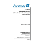
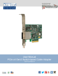
The Embedded I/O Company TPCE275 PCI Express XMC Carrier Version 1.0 User Manual Issue 1.0.2 April 2013 TEWS TECHNOLOGIES GmbH Am Bahnhof 7 25469 Halstenbek, Germany Phone: +49 (0) 4101 4058 0 Fax: +49 (0) 4101 4058 19 e-mail: [email protected] www.tews.com TPCE275-10R PCI Express x1 Carrier for one XMC module, +12V Power Supply from PCIe Connector, 12V VPWR, J14 I/O, J16 I/O, JTAG connections to XMC module via 10-pin header TPCE275-11R PCI Express x1 Carrier for one XMC module, +12V Power Supply from PCIe Connector, 5V VPWR, J14 I/O, J16 I/O, JTAG connections to XMC module via 10-pin header TPCE275-20R PCI Express x1 Carrier for one XMC module, +12V power supply from external PCIe graphics power connector used (cable adapter enclosed in order), 12V VPWR, J14 I/O, J16 I/O, JTAG connections to XMC module via 10-pin header This document contains information, which is proprietary to TEWS TECHNOLOGIES GmbH. Any reproduction without written permission is forbidden. TEWS TECHNOLOGIES GmbH has made any effort to ensure that this manual is accurate and complete. However TEWS TECHNOLOGIES GmbH reserves the right to change the product described in this document at any time without notice. TEWS TECHNOLOGIES GmbH is not liable for any damage arising out of the application or use of the device described herein. Style Conventions Hexadecimal characters are specified with prefix 0x, i.e. 0x029E (that means hexadecimal value 029E). TPCE275-21R PCI Express x1 Carrier for one XMC module, +12V power supply from external PCIe graphics power connector used (cable adapter enclosed in order), 5V VPWR, J14 I/O, J16 I/O, JTAG connections to XMC module via 10-pin header For signals on hardware products, an ‚Active Low’ is represented by the signal name with # following, i.e. IP_RESET#. Access terms are described as: W Write Only R Read Only R/W Read/Write R/C Read/Clear R/S Read/Set 2013 by TEWS TECHNOLOGIES GmbH All trademarks mentioned are property of their respective owners. TPCE275 User Manual Issue 1.0.2 Page 2 of 15 Issue Description 1.0.0 Initial Issue 1.0.1 Added information about the stable time for the XMC slot power supply 1.0.2 New board revision: - Modification of power supply voltages on connectors X5 and X6: o VPWR no longer available, is now always +12V o Additionally, +5V are now also available on X6 in TPCE275-x1 variants o All voltages are now fuse protected TPCE275 User Manual Issue 1.0.2 Date September 2012 October 2012 April 2013 Page 3 of 15 Table of Contents 1 2 3 PRODUCT DESCRIPTION ........................................................................................... 6 TECHNICAL SPECIFICATION ..................................................................................... 7 HANDLING AND OPERATING INSTRUCTIONS ......................................................... 8 3.1 3.2 3.3 3.4 3.5 4 XMC INTERFACE ......................................................................................................... 9 4.1 4.2 4.3 5 Power Limits for XMC Modules ..................................................................................................... 9 Stable Power Supply....................................................................................................................... 9 Installation of an XMC Module ....................................................................................................... 9 INDICATORS .............................................................................................................. 10 5.1 6 ESD Protection ................................................................................................................................ 8 Power Limits for XMC Modules ..................................................................................................... 8 Installation of XMC Modules .......................................................................................................... 8 Installation of TPCE275-2xR .......................................................................................................... 8 Installation of TPCE275-x0R .......................................................................................................... 8 LED Indicators ............................................................................................................................... 10 PIN ASSIGNMENTS ................................................................................................... 11 6.1 XMC J15 ......................................................................................................................................... 11 6.2 XMC J14 Rear-I/O (X4 - VG64 Connector) ................................................................................... 12 6.3 XMC J16 Rear-I/O (50-Pin Flat Cable Connectors) .................................................................... 13 6.3.1 X5 - J16 Differential I/O Lines ................................................................................................. 13 6.3.2 X6 - J16 Single-Ended I/O Lines ............................................................................................ 14 6.4 10-Pin JTAG Header (X7) .............................................................................................................. 15 TPCE275 User Manual Issue 1.0.2 Page 4 of 15 List of Figures FIGURE 1-1 : TPCE275 BLOCK DIAGRAM ..................................................................................................... 6 FIGURE 5-1 : ONBOARD LED PLACEMENT ................................................................................................ 10 List of Tables TABLE 2-1 : TECHNICAL SPECIFICATION ..................................................................................................... 7 TABLE 4-1 : CURRENT LIMITS FOR THE XMC MODULES ........................................................................... 9 TABLE 5-1 : ONBOARD LED DESCRIPTION ................................................................................................ 10 TABLE 6-1 : XMC J15 PIN ASSIGNMENT ..................................................................................................... 11 TABLE 6-2 : X4 - J14 I/O PIN ASSIGNMENT ................................................................................................. 12 TABLE 6-3 : X5 - J16 DIFFERENTIAL I/O LINES PIN ASSIGNMENT ..........................................................13 TABLE 6-4 : X6 - J16 SINGLE-ENDED I/O LINES PIN ASSIGNMENT .........................................................14 TABLE 6-5 : X7 - JTAG HEADER ................................................................................................................... 15 TPCE275 User Manual Issue 1.0.2 Page 5 of 15 1 Product Description The TPCE275 is a standard height PCI Express, Revision 1.1 compatible module that provides one slot for a single-width XMC module used to build modular, flexible and cost effective I/O solutions for all kinds of applications like process control, medical systems, telecommunication and traffic control. The TPCE275 supports XMC front-panel I/O, and also XMC P14 and P16 Rear-I/O. XMC P14 Rear-I/O is offered through a VME P2 style connector (IEC 60603-2, Type C). The I/O mapping of P14 complies with VITA-35 (“PMC P4 to VME-P2, Rows A-C mapping”). XMC P16 Rear-I/O is implemented through two 50 pin, 0.1 inch flat ribbon cable connectors providing access to all P16 I/O lines. The single-ended signals of P16 are all routed to one flat cable connector, while the differential signals are routed to the second connector. The operating temperature range is 0°C to +70°C. Figure 1-1 : TPCE275 Block Diagram TPCE275 User Manual Issue 1.0.2 Page 6 of 15 2 Technical Specification Mechanical and Electrical Interfaces PCI Express PCI Express x1, Revision 1.1 Standard Height Full Length XMC Slot ANSI/VITA 42.0 (R2008) ANSI/VITA 42.3 Single-Width XMC Interface Number of XMC Slots 1 XMC I/O Access XMC Front Panel I/O XMC P14 Rear I/O through VG64 Right Angle Male Connector XMC P16 Rear I/O through 2x50-pin Flat Cable Connectors Maximum Current for all Rear I/O Lines is 0.5A! I/O Power Supply Access +12V, +3.3V and +5V (TPCE275-x1 variants) are available on X5 and X6. All voltages are fuse protected. The maximum current for each voltage is 0.5A! On Board Devices PCI Express ReDriver PI2EQX4401D (Pericom) Physical Data Power Requirements 125mA maximum @ +3.3V DC 75mA maximum @ +12V DC Additional power is required by the XMC Module! Power Stable for XMC Slot The power supply for the XMC slot is stable approximately 20ms after the system power supply is stable. Maximum Power for XMC Slot The maximum power available for an XMC module is variant dependent. Please see chapter “Power Limits for XMC Modules” for detailed information. Temperature Range Operating Storage MTBF TPCE275-1xR: 664000 h TPCE275-2xR: 637000 h 0°C to +70°C 0°C to +70°C MTBF values shown are based on calculation according to MIL-HDBK-217F and MIL-HDBK-217F Notice 2; Environment: GB 20°C. The MTBF calculation is based on component FIT rates provided by the component suppliers. If FIT rates are not available, MIL-HDBK-217F and MIL-HDBK-217F Notice 2 formulas are used for FIT rate calculation. Humidity 5 – 95 % non-condensing Weight TPCE275-10R: TPCE275-11R: TPCE275-20R: TPCE275-21R: 114 g 120 g 116 g 122 g Table 2-1 : Technical Specification TPCE275 User Manual Issue 1.0.2 Page 7 of 15 3 Handling and Operating Instructions 3.1 ESD Protection The TPCE275 is sensitive to static electricity. Packing, unpacking and all other handling of the TPCE275 has to be done in an ESD/EOS protected Area. 3.2 Power Limits for XMC Modules The PCIe specification limits the power for PCIe add-in cards. These limitations have implications for the use of XMC modules. Refer to the chapter “Power Limits for XMC Modules” for details. 3.3 Installation of XMC Modules Before mounting XMC Modules on the TPCE275, be sure that the system is powered off. Also, follow the installation instructions in the “XMC Interface” chapter. 3.4 Installation of TPCE275-2xR For the TPCE275-2xR variants, it is imperative to always connect a PCI Express VGA power connector to the TPCE275, even if no PMC is mounted. 3.5 Installation of TPCE275-x0R For the TPCE275-x0R variants, VPWR is +12V. This voltage is directly connected from the PCIe connector. The PCIe specification allows for tolerances of ±8%, whereas the XMC specification allows only for ±5%. This has to be taken into consideration before plugging the XMC module onto the TPCE275-x0R. TPCE275 User Manual Issue 1.0.2 Page 8 of 15 4 XMC Interface 4.1 Power Limits for XMC Modules The following current limits have to be taken into account when choosing the appropriate TPCE275 for the power requirements of the XMC module. TPCE275 Voltage TPCE275-1xR TPCE275-2xR VPWR VPWR Current Limits 3.3V 2.0 A 5V (TPCE275-11R) 1.2 A 12V (TPCE275-10R) 0.5 A +12V 200 mA 3.3V 7.5 A 5V (TPCE275-21R) 5.0 A 12V (TPCE275-20R) 2.1 A +12V 200 mA Table 4-1 : Current Limits for the XMC Modules 4.2 Stable Power Supply The power supply for the XMC slot is stable approximately 20ms after the system power supply is stable. 4.3 Installation of an XMC Module The XMC modules are mounted to the TPCE275 prior to installation into the system. If the XMC has a front panel, first remove the cover from the XMC front panel cut-out of the TPCE275. Install the XMC at an angle so that the XMC front panel penetrates the XMC front panel cut-out. Then rotate down to mate with the XMC connectors on the TPCE275. If the XMC has no front panel, simply plug in the XMC, and leave the cover in the XMC front panel cut-out of the TPCE275. After the XMC module has been installed, it can be mounted on the TPCE275 using the mounting screws that come with the XMC module. There are four screw mounting locations, two at the XMC front panel and two at the standoffs near the XMC bus connectors. Before installing an XMC module, be sure that the power supply for the TPCE275 is turned off. The components are Electrostatic Sensitive Devices (ESD). Use an anti-static mat connected to a wristband when handling or installing the components. TPCE275 User Manual Issue 1.0.2 Page 9 of 15 5 Indicators 5.1 LED Indicators A01 F19 A01 F19 V13 V3 V8 V6 V2 V10 The TPCE275 provides a couple of board-status LEDs as shown below. Figure 5-1 : Onboard LED Placement LED Color V6 SIG_A Green V8 SIG_B Green V2 3.3V Power Good Green V3 1.8V Power Good Green State Description Off PCIe TX link is down On PCIe TX link is up Off PCIe RX link is down On PCIe RX link is up Off 3.3V Power Supply is not OK On 3.3V Power Supply is OK Off 1.8V Power Supply is not OK On 1.8V Power Supply is OK Off 5V Power Supply is not OK On 5V Power Supply is OK Off 12V Power Supply is not OK On 12V Power Supply is OK Dependent on VPWR V10 VPWR Power Good Green V13 VPWR Power Good Green Table 5-1 : Onboard LED Description TPCE275 User Manual Issue 1.0.2 Page 10 of 15 6 Pin Assignments 6.1 XMC J15 01 02 A B C PET0p0 PET0n0 3,3V GND GND 03 04 GND GND GND GND PERST# TCK VPWR 1) GND GND 3,3V GND GND 07 08 F VPWR 1) TRST E 3,3V 05 06 D TMS VPWR 1) GND GND +12V 3,3V GND GND TDI VPWR 1) GND GND -12V 09 VPWR 10 GND GND 11 PER0p0 PER0n0 12 GND GND GND GND GND GND GA0 VPWR GA1 GND 3,3V_AUX 13 14 TDO 1) GND 2) GA2 VPWR GND SMCLK GND 15 16 6) VPWR GND GND GND GND MVMRO 3) GND SMDAT GND 6) 17 18 19 REFCLK+0 REFCLK-0 GND WAKE# GND 4) ROOT0# 5) Table 6-1 : XMC J15 Pin Assignment Notes: 1) JTAG lines are routed to a 10pin header onboard, not to the PCIe edge card connector 2) 3.3V_AUX is connected to the PCIe edge card connector, so it is up to the mainboard to deliver this power supply. If a mainboard does not provide this power supply, it can be changed to 3.3V on the TPCE275 with a resistor. 3) MVMRO is set to logic high by default, prohibiting write access. It can be changed via a resistor. 4) WAKE# is connected to the PCIe edge card connector, so it is up to the mainboard to provide for this signal. If this is not the case, WAKE# may be separated from the mainboard via a resistor. 5) ROOT# is not supported; this pin is not connected on the TPCE275 by default. It can be pulled high via a resistor. 6) SMCLK and SMDAT are not connected to the PCIe edge card connector by default. Both signals can be connected via series resistors. TPCE275 User Manual Issue 1.0.2 Page 11 of 15 6.2 XMC J14 Rear-I/O (X4 - VG64 Connector) The TPCE275 routes the XMC I/O lines to the VG64 connector compliant to VITA-35 (“PMC P4 to VME-P2, Rows A-C mapping”). The actual signal assignment of the XMC P14 connector is XMC specific. Connector Type DIN 41612 2.54mm - Right Angle Male Connector - Type C Source & Order Info ERNI 384047 Signal Pin Pin Signal I/O 1 c1 a1 I/O 2 I/O 3 c2 a2 I/O 4 I/O 5 c3 a3 I/O 6 I/O 7 c4 a4 I/O 8 I/O 9 c5 a5 I/O 10 I/O 11 c6 a6 I/O 12 I/O 13 c7 a7 I/O 14 I/O 15 c8 a8 I/O 16 I/O 17 c9 a9 I/O 18 I/O 19 c10 a10 I/O 20 I/O 21 c11 a11 I/O 22 I/O 23 c12 a12 I/O 24 I/O 25 c13 a13 I/O 26 I/O 27 c14 a14 I/O 28 I/O 29 c15 a15 I/O 30 I/O 31 c16 a16 I/O 32 I/O 33 c17 a17 I/O 34 I/O 35 c18 a18 I/O 36 I/O 37 c19 a19 I/O 38 I/O 39 c20 a20 I/O 40 I/O 41 c21 a21 I/O 42 I/O 43 c22 a22 I/O 44 I/O 45 c23 a23 I/O 46 I/O 47 c24 a24 I/O 48 I/O 49 c25 a25 I/O 50 I/O 51 c26 a26 I/O 52 I/O 53 c27 a27 I/O 54 I/O 55 c28 a28 I/O 56 I/O 57 c29 a29 I/O 58 I/O 59 c30 a30 I/O 60 I/O 61 c31 a31 I/O 62 I/O 63 c32 a32 I/O 64 Connector view c a 1 2 31 32 PCB Table 6-2 : X4 - J14 I/O Pin Assignment TPCE275 User Manual Issue 1.0.2 Page 12 of 15 6.3 XMC J16 Rear-I/O (50-Pin Flat Cable Connectors) 6.3.1 X5 - J16 Differential I/O Lines Pin-Count 50 Connector Type Flat Cable Connector Source & Order Info AMP 104340 Pin Assignment Description Pin DP00- Connector View Pin Description 1 2 DP00+ DP01- 3 4 DP01+ DP02- 5 6 DP02+ 8 DP03+ 10 DP04+ 1 3 2 4 DP03- 7 DP04- 9 DP05- 11 12 DP05+ DP06- 13 14 DP06+ DP07- 15 16 DP07+ DP08- 17 18 DP08+ DP09- 19 20 DP09+ DP10- 21 22 DP10+ DP11- 23 24 DP11+ DP12- 25 26 DP12+ DP13- 27 28 DP13+ DP14- 29 30 DP14+ DP15- 31 32 DP15+ DP16- 33 34 DP16+ DP17- 35 36 DP17+ DP18- 37 38 DP18+ DP19- 39 40 DP19+ - 41 42 - GND 43 44 GND GND GND 47 49 48 50 45 46 3.3V 1) 47 48 3.3V 1) 3.3V 1) 49 50 3.3V 1) Table 6-3 : X5 - J16 Differential I/O Lines Pin Assignment 1) All voltages are fuse protected. The maximum current for each voltage is 0.5A! TPCE275 User Manual Issue 1.0.2 Page 13 of 15 6.3.2 X6 - J16 Single-Ended I/O Lines Pin-Count 50 Connector Type Flat Cable Connector Source & Order Info AMP 104340 Pin Assignment Description Pin UD_F1 Connector View Pin Description 1 2 UD_C1 UD_F2 3 4 UD_C2 UD_F3 5 6 UD_C3 8 UD_C4 10 UD_C5 1 3 2 4 UD_F4 7 UD_F5 9 UD_F6 11 12 UD_C6 UD_F7 13 14 UD_C7 UD_F8 15 16 UD_C8 UD_F9 17 18 UD_C9 UD_F10 19 20 UD_C10 UD_F11 21 22 UD_C11 UD_F12 23 24 UD_C12 UD_F13 25 26 UD_C13 UD_F14 27 28 UD_C14 UD_F15 29 30 UD_C15 UD_F16 31 32 UD_C16 UD_F17 33 34 UD_C17 UD_F18 35 36 UD_C18 UD_F19 37 38 UD_C19 +5V 1) 2) 39 40 +5V 1) 2) +5V 1) 2) 41 42 +5V 1) 2) 43 GND 47 49 48 50 44 GND GND 45 46 +12V_PCIe 2) 47 48 +12V_PCIe 2) +12V_PCIe 2) 49 50 +12V_PCIe 2) GND Table 6-4 : X6 - J16 Single-Ended I/O Lines Pin Assignment 1) +5V are only available in TPCE275-x1 variants 2) All voltages are fuse protected. The maximum current for each voltage is 0.5A! TPCE275 User Manual Issue 1.0.2 Page 14 of 15 6.4 10-Pin JTAG Header (X7) The 10-Pin JTAG Header (Connector X7) is connected to the XMC J15 connector with the following pin assignment. All pins are described from the perspective of the XMC module. Signal TCK Pin 1 Connector View *) 1 2 Pin Signal 2 GND TMS 3 4 GND TDO 5 6 GND TDI 7 8 GND 10 - TRST# 9 9 10 Table 6-5 : X7 - JTAG Header Notes: *) Pin 1 has a squared pad for better recognition TPCE275 User Manual Issue 1.0.2 Page 15 of 15