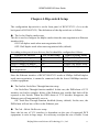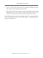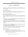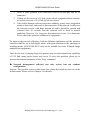
1
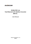
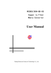
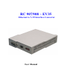
RC 907/908 – EV35 Ethernet to V.35 Interface Converter User Manual RC907/908-EV35 User Guide CONTENTS CHAPTER 1. INTRODUCTION.................................................................................................... 2 1.1 PRODUCT INTRODUCTION ......................................................................................................... 2 1.2 PRODUCT SPECIFICATIONS ........................................................................................................ 2 1.3 EXPLANATION FOR THE FRONT PANEL AND INDICATORS ........................................................... 4 1.3.1 The Indicators on the Front Panel ................................................................................... 4 1.3.2 The Definitions of Indicators............................................................................................ 4 CHAPTER 2. CONNECTION CONFIGURATION ..................................................................... 6 2.1 INTERFACE CONVERTER INTERCONNECTION ............................................................................. 6 2.2 TYPICAL APPLICATIONS ............................................................................................................ 6 2.3 DUPLEX MODE CONFIGURATION .............................................................................................. 7 2.4 CONNECTION WITH OTHER NETWORK EQUIPMENT (AT ETHERNET PORT)................................... 7 CHAPTER 3. INSTALLATION AND PREPARATION ............................................................... 8 CHAPTER 4. DIP-SWITCH SETUP ............................................................................................11 CHAPTER 5. TROUBLESHOOTING......................................................................................... 14 Beijing Raisecom Science & Technology Co., Ltd. 1 RC907/908-EV35 User Guide Chapter 1. Introduction 1.1 Product Introduction RC907/908-EV35 series interface converter, or media converter, is designed to transmit Ethernet data over V.35 network. Since more and more V.35 network resources are being deployed, various types of data transmission solutions that make use of V.35 links will be widely accepted by end-users. RC907-EV35 series interface converters are standalone interface converters. Every unit of device has an independence built-in power supply, and can be placed on the table. RC908-EV35 series interface converters are slide-in modular interface converters. Dynamix RC RC can series be installed into Raisecom series 16-slot chassis (19” 3U high RCThey 908-EV35 interface converters are slide-in modular interface converters. They can be installed into Dynamix (19' 3U chassis), 4-slot chassis (19' chassis), or 4-slot chassis RC (19”series 1U16-slot high chassis chassis), or high single slot orchassis. When 1U high chassis), or single slot chassis. installed into 4-slot chassis, bewith mixed other Raisecom When installed into16-slot 16-slot oror4-slot chassis, it canitbecan mixed otherwith Dynamix Series products series ( e.g. copper-to-fiber media converters, single-port multiplexers) to enableoptical uniform network management. products (e.g. copper-to-fiber mediaoptical converters, single-port multiplexers) to RC 907-EV35 interface converters can be deployed at the remote site to work in pairs with RC908-EV35. enable uniform network management. RC907-EV35 interface converters can be deployed at the remote site to work in pairs with RC908-EV35. RC907/908-EV35 (Rev. B) has interoperability with the previous version (Rev. A). The differences between the two versions are only at Ethernet interfaces. So it is not necessary to consider other properties when they interconnect with each other. The bandwidth setup and clock phase configuration of Rev. B are the same as those of Rev. A. Please consult our technical support if encountering any problem. 1.2 Product Specifications V.35 interface: Physical characteristics: Connector type: Working mode: Bit rate: Compliant with V.35 interface standard HDB26 female connector (26 pin female port) DTE Dependent on DCE equipment, the maximum bit rate up Beijing Raisecom Science & Technology Co., Ltd. 2 RC907/908-EV35 User Guide to 8Mbps Ethernet interface Connector type: RJ-45 interface, CAT.5/enhanced CAT.5 wires, and the maximum transmission distance up to 100m Bit rate: 10Mbps Duplex mode: Full/half duplex auto-negotiation Compliance: IEEE 802.3 Other capabilities: 1. The function of reporting V.35 signal loss alarm to Switches 2. Supports IEEE 802.1d Spanning Tree and IEEE 802.1q VLAN protocols 3. Supports over-sized Ethernet data frame up to 1595 bytes. 4. Supports IEEE 802.3x flow control in full duplex mode 5. Supports back pressure flow control in half duplex mode 6. Built-in 1k MAC address table with address filtering capability to improve the efficiency of the V.35 link 7. Built-in SDRAM 64M memory to alleviate data congestion Network management capabilities for RC908-EV35 (NM software is optional) The network management capabilities include: 1. Set up the phase relationship between transmit/receive data and transmit/receive clock at V.35 interface; 2. Set up of the buffer capacity; 3. Report operating status of Ethernet port to SNMP server; 4. Set up full/half duplex mode at Ethernet interface; 5. Set up fault-pass-through function; 6. Close the Ethernet interface and disable the modular through NMS software; 7. Keep history record of all events. Beijing Raisecom Science & Technology Co., Ltd. 3 RC907/908-EV35 User Guide 1.3 Explanation for the Front Panel and Indicators 1.3.1 The Indicators on the Front Panel Ethernet Link ETH Data TX/RX Action RAISECOM RC907-EV35 LNK DTE ACT PWR UTP Power Supply 1 23 4 5 6 7 8 FDX SW Full Duplex Figure 1. The front panel of RC907-EV35 Ethernet Link ETH Data TX/RX Action DTE PWR ACT UTP Power Supply FDX RC908-EV35 LNK Full Duplex Figure 2. The front panel of RC908-EV35 1.3.2 The Definitions of Indicators Ethernet Link (LNK): On: Ethernet link is properly connected Off: Ethernet link is disconnected Ethernet data TX/RX Action (ACT): Flashing: Transmitting or receiving data Full Duplex Mode (FDX): On: Full duplex mode Off: Half duplex mode Power supply (PWR): On: The power supply is in good condition Off: The power supply is disconnected. Beijing Raisecom Science & Technology Co., Ltd. 4 RC907/908-EV35 User Guide The connector types of the interface are as the following. V.35 interface: The DTE connector: HDB26 female connector. Please refer to Chapter 3 for details of the interface definition and cable connection. Ethernet interface: The UTP connector: Unshielded twisted pair connector for Ethernet. Please refer to Chapter 3 for details of the interface definition and cable connection. Beijing Raisecom Science & Technology Co., Ltd. 5 RC907/908-EV35 User Guide Chapter 2. Connection Configuration 2.1 Interface Converter Interconnection When connecting interface converters, it is required to comply with the specific connection article numbers according to the following table. Otherwise, the link will not be established, or abnormal data transmission will occur. The Host Site RC908-EV35 RC908-EV35 The Remote Site RC908-EV35 RC907-EV35 2.2 Typical Applications Interface Converter 10Base-T V.35 V.35 DDN Interface Converter 10Base-T Ethernet Ethernet 以太网 switch switch 交换机 DDN leased line is utilized to extend the data transmission distance of Ethernet IEEE802.1q protocol is supported to ensure the key features of most mainstream products, such as between-switch VLAN and TRUNK functions. RC907/908-EV35 series interface converters can be used to provide private DDN network solutions for organizations and departments such as finance, government and education etc. Beijing Raisecom Science & Technology Co., Ltd. 6 RC907/908-EV35 User Guide 2.3 Duplex Mode Configuration RC907/908-EV35 series Ethernet to V.35 interface converters are devices used to conduct media conversions and extend transmission distances. When connecting RC907/908-EV35 interface converters with other network equipment, they need to cooperate with each other to work properly. Different duplex mode configurations on network equipment interfaces will affect the transmission efficiency of the network. The recommended configurations are listed in the following table when interconnecting different network equipment. The working mode of other network RC907/908-EV35 working mode equipment 10Mbps full duplex 10Mbps half duplex Auto-negotiation 100Mbps full duplex 100Mbps half duplex The interface converter shall be configured to full duplex mode when auto-negotiation fails. The interface converter shall be configured to half duplex mode when auto-negotiation fails. (Factory default) No need for configuration. (Factory default) The interface converter cannot connect with 100Mbps interfaces of other equipment. The interface converter cannot connect with 100Mbps interfaces of other equipment. 2.4 Connection with other network equipment (at Ethernet port) RC907/908-EV35 series interface converter supports MDI/MDIX auto-sensing. Beijing Raisecom Science & Technology Co., Ltd. 7 RC907/908-EV35 User Guide Chapter 3. Installation and Preparation 1. First, please choose the appropriate configuration structure to be applied, referring to the sketch map of recommended basic connection structure. 2. Make sure that the V.35 cable matches the connected equipment. If RC907/908-EV35 interface converter is used to connect DCE, please use DTE cable. 3. Use CAT.5 UTP to connect the Ethernet port of RC907/908-EV35 interface converter, and make sure that the length of the UTP cable does not exceed 100m. NO.1 pin NO.8 pin The pin definitions of the RJ45 interface on RC907/908-EV35 interface converter are as follows. Pin number 1 2 3 4 5 6 7 8 Definition TX+ TX- RX+ Not Used Not Used RX- Not Used Not Used Details Output+ Output- Input+ Hang Hang Input- Hang Hang The following diagram indicates the correct line sequence of straight-through UTP cable. RC907/908-EV35 UTP-RJ45 Pin 1 Pin 2 Pin 3 Pin 6 Ethernet device RJ45 Pin 1 Pin 2 Pin 3 Pin 6 Beijing Raisecom Science & Technology Co., Ltd. 8 RC907/908-EV35 User Guide The following diagram indicates the correct line sequence of crossover UTP cable. RC907/908-EV35 UTP-RJ45 Pin 1 Pin 2 Pin 3 Pin 6 Host network card RJ45 Pin 1 Pin 2 Pin 3 Pin 6 In these two connection types, Pin 1 and Pin 2 are in a twisted pair, and so are Pin 3 and Pin 6. Since RC907/908-EV35 interface converters support MDI/MDIX auto-sensing function, users can adopt either kind of the above cables. 4. The V.35 interface adopts HDB26 female connector,the definitions are as follows: Pin Name Input/Output Pin Number Chassis Ground — CGND 1 Signal Ground — GND 7 Receive Data (A) — RD(A) I 3 Receive Data (B) — RD(B) I 21 Receive Timing (A) — RCK(A) I 17 Receive Timing (B) — RCK(B) I 25 Send Data (A) — TD(A) O 2 Send Data (B) — TD(B) O 11 Send Timing (A) — TCK(A) I 15 Send Timing (B) — TCK(B) I 23 Terminal Timing (A) — SCTE(A) O 24 Terminal Timing (B) — SCTE(B) O 16 Request to Send — RTS O 4 Clear to Send — CTS I 5 Data Set Ready — DSR I 6 Data Carrier Detect — DCD I 8 Data Terminal Ready — DTR O 20 I—input; O—output Note: It is strictly forbidden to hot-swap the V.35 interface with power supply applied! Beijing Raisecom Science & Technology Co., Ltd. 9 RC907/908-EV35 User Guide 5. RC907/908-EV35 interface converter must work in pairs point to point. There shall be DCE equipment between two converters. It cannot connect with the third party’s branded interface converter. 6. Ambience: Working temperature: 0-45℃ Humidity: 5%~90% non-condensing 7. Power supply: AC/DC optional AC: 220V/50Hz (input ranges form 165 to 265V) DC: -48V (input ranges from –36 to -72V) Power consumption: ≤ 5W 8. Dimensions (for RC907-EV35 standalone interface converter) Dimension: 120 (width) x 32 (height) x 157 (depth) mm 9. We recommend that users install and configure the interface converter after reading the next chapter and finishing the relevant preparations. Beijing Raisecom Science & Technology Co., Ltd. 10 RC907/908-EV35 User Guide Chapter 4. Dip-switch Setup The configuration dip-switch is on the front panel of RC907-EV35. (It is on the back panel of RC908-EV35.) The definitions of the dip-switch are as follows. The 1st bit: Duplex mode setup This bit is used to configure the duplex mode when the auto-negotiation at Ethernet interface fails. ON: Full duplex mode when auto-negotiation fails OFF: Half duplex mode when auto-negotiation fails (default) According to the port of user devices, this bit should be configured as follows. Port of User Devices The 1st Bit Setup Actual Working Mode 10/100Mbps auto-negotiation Any 10Mbps full duplex mode Forced 10Mbps half duplex OFF 10Mbps half duplex mode Forced 10Mbps full duplex ON 10Mbps full duplex mode 10Mbps full/half duplex Any 10Mbps full duplex mode auto-negotiation Since the Ethernet interface of RC907/908-EV35 works at 10Mbps full/half duplex mode auto-negotiation, it cannot be connected with the forced 100Mbps interface of other equipment. The 2nd bit: Fault-Pass-Through function setup On: Fault-Pass-Through function enabled. In this case, the DSR alarm of V.35 interface can lead to complete failure of the Ethernet port, and the link fault will be reported to the Switch. When the DSR alarm of V.35 interface disappears, the Ethernet port will automatically recover. Off: Fault-Pass-Through function disabled (factory default). In this case, the DSR alarm will not have effect on the Ethernet port. The 3rd ~5th bit: Buffer size setup Since the bit rate of V.35 interface is dependent on the rate of connected DCE equipment, it varies in large range. It is necessary to adjust the size of buffer. It can Beijing Raisecom Science & Technology Co., Ltd. 11 RC907/908-EV35 User Guide not only prevent long time delay, but also avoid packet loss caused by sudden data flooding. It is suggested that the buffer size be configured as the following table. WAN Interface Rate (bit/s) ≥2M > 1M > 512K > 256K > 64K ≤64K 3rd Bit OFF OFF ON ON ON ON DIP-switch 4th Bit OFF ON OFF ON ON ON 5th Bit OFF ON ON OFF ON ON The 6th bit: TX CLK phase selection switch. It provides various options for different phase relationships of transmitting data and TX clocking at V.35 interface between different brands DCE equipment. OFF: positive phase (default). ON: negative phase. The 7th bit: RX CLK phase selection switch. It provides various options for different phase relationships of receiving data and RX clocking at V.35 interface between different brands DCE equipment. OFF: positive phase (default). ON: negative phase. The 8th bit: Reserved bit. The factory default setup of the dip-switch: DIP-switch 1 2 3 4 5 6 7 8 ON OFF ■ ■ ■ ■ ■ ■ ■ ■ Details Half Fault Maximum buffer size Positive Positive No duplex Pass phase phase Meaning Through disabled Note: 1. Please use the 1st bit to configure the half/full duplex mode of converters following the instructions in 2.3 Full Duplex Mode Configuration, Chapter 2. Beijing Raisecom Science & Technology Co., Ltd. 12 RC907/908-EV35 User Guide 2. The 3rd ~ 5th bits of the dip-switch can be configured according to the above table to achieve the best transmission performance. 3. Only if all bits of the dip-switch are set to the factory default status, network management software can command, configure and inquire the status of the interface converter; Otherwise, the software has the inquiry function only. After finishing the above steps, the power supply of the device can be switched on. If there is any problem, please refer to the last chapter – “Troubleshooting” for operation and maintenance. Beijing Raisecom Science & Technology Co., Ltd. 13 RC907/908-EV35 User Guide Chapter 5. Troubleshooting If there is any problem during the installation and operation, please try the following solutions. If the problem cannot be solved yet, please contact distributors for technical support. PWR indicator is not on Answer: Power supply fails. Check whether the power supply is working properly, and make sure the power cable for –48V DC is not reversely connected. Link indicator (LNK) is off Answer: Please check if the link is disconnected. Please check whether the bit rate matches. The bit rate of the Ethernet equipment interface connected with the interface converter should be auto-negotiation or fixed 10Mbps. LNK is on and ACT is flashing rapidly and continuously, but the equipment cannot be pinged through. Answer: In most cases, the reason is that the interface converter is connected with 100Mbps network equipment. RC907/908-EV35 can only connect with 10Mbps or auto-negotiation interfaces. Please verify the bit rate of the connected network equipment. LNK is on and ACT is flashing intermittently at normal status, but the equipment cannot be pinged through. Answer: The reason may be that the phase relationship between the data and the clock of DCE V.35 interface is not the same as the configuration of the interface converter. Please reconfigure the 6th and 7th bits of the dip-switch. Severe packet loss Answer: The possible reasons for severe packet loss are as follows: 1. The duplex mode of the Ethernet interface of the interface converter is not matching with that of the Ethernet equipment. Please refer to 2.3 Full Duplex Mode Configuration, Chapter 2. Beijing Raisecom Science & Technology Co., Ltd. 14 RC907/908-EV35 User Guide 2. 3. 4. There is some problem with connection between twisted pair and RJ-45 connector. If there are bit errors in V.35 link, please check equipment alarm function, or test bit error rate of V.35 link by bit error tester. If the traffic through converter increases suddenly, it may cause congestion within a short time, and result in disconnection of the network. In this case, the network service with huge amount of traffic should be paused and restarted after 10 seconds, and the network will be back to normal condition. However, if a long time disconnection occurs, it is abnormal. Please check the operation condition of equipments. To improve the network efficiency, both the Ethernet equipment and the interface converter shall be set in full duplex mode, with great attention to the matching of working modes. RC907/908-EV35 may not be suitable for some IP-based image transmission equipments. Since the bit rate of pinging large-size packets may exceed transmission capability of V.35 link, many packet losses may occur. To solve this problem, please try to increase the timeout parameter of the ‘Ping’ command. Network management software can only review, but not conduct configuration Answer: The possible reason is that some bits of the dip-switch are not set on the default status. Please refer to Chapter 4 for details. Beijing Raisecom Science & Technology Co., Ltd. 15