1
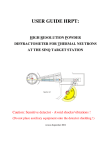
Tau CNV User’s Manual Tau Color Night Vision Camera 10-10032-01 Rev A1 2011 FLIR Advanced Imaging Systems Tau CNV Camera User’s Manual ECO: 594 Page 1 of 49 FLIR Advanced Imaging Systems, Inc. FLIR Advanced Imaging Systems (AIS) produces a wide range of high performance cameras for applications that demand high resolution, high data rates, wide dynamic range, high sensitivity (low light), low power and small form factors (space claim) packaging. FLIR AIS satisfies the needs of our customers by applying the best camera sensor technologies to our customers’ challenging applications, and coupling these sensor technologies with low noise and precision analog design, proprietary thermal stabilization, and real-time image processing. FLIR AIS’ cameras are designed and built in our ISO certified facility and each camera is 100% tested and inspected using the photon transfer curve methods and best manufacturing practices to verify performance to technical specifications and to ensure total product quality. FLIR AIS designs, develops, and manufactures its high performance cameras at its facility in Colorado Springs, Colorado, USA, and is part of FLIR Systems Inc., a world leader in the design, manufacture, and marketing of sensor systems that enhance perception and awareness for a wide variety of users in the commercial, industrial, and government markets, internationally as well as domestically. Contact Information: FLIR Systems, Inc. FLIR Advanced Imaging Systems, Inc. 5061 North 30th Street, Suite 103 Colorado Springs, CO 80919 USA (719) 598-6006 phone (719) 598-6556 fax http://www.flir.com/cvs/cores [email protected] 10-10032-01 Rev A1 2011 FLIR Advanced Imaging Systems Tau CNV Camera User’s Manual ECO 594 page 2 of 49 Table of Contents 1 INTRODUCTION .................................................................................................................. 6 2 CAMERA POWER ................................................................................................................ 6 2.1 2.2 2.3 IMPORTANT SYSTEM GROUNDING REQUIREMENTS ........................................................................................ 6 IMPORTANT POWER-UP SEQUENCING REQUIREMENTS ................................................................................... 6 IMPORTANT CLEANING AND LENS INSTALLATION INFORMATION .................................................................. 6 3 CAMERA FEATURES AND FUNCTIONS ....................................................................... 7 3.1 3.2 3.3 3.4 3.5 3.6 3.7 3.8 3.9 3.10 3.11 HIGH DEFINITION, 1280 X 1024 IMAGER ........................................................................................................ 7 PROGRAMMABLE ELECTRONIC SHUTTER ....................................................................................................... 8 AUTOMATIC GAIN CONTROL .......................................................................................................................... 8 AUTOMATIC COLOR AND WHITE BALANCE .................................................................................................... 8 SELECTABLE NOISE SUPPRESSION .................................................................................................................. 8 INTEGRATED, MOTORIZED, IR CUT FILTER OPTION ....................................................................................... 9 TRIGGER MODES - FREE RUN, OR EXTERNAL TRIGGER .................................................................................. 9 FLAT FIELDING (NON-UNIFORMITY CORRECTION)....................................................................................... 10 DIGITAL AND ANALOG VIDEO OUTPUT OPTIONS ......................................................................................... 10 SMALL SPACE-CLAIM AND LOW POWER REQUIREMENTS ............................................................................ 10 EFFECTIVE DAY AND NIGHT COLOR THROUGH BUILT-IN FILTER SLIDER (OPTIONAL) ................................. 10 4 CAMERA SPECIFICATIONS ........................................................................................... 11 4.1 4.2 CAMERA SPECIFICATIONS ............................................................................................................................ 11 QUANTUM EFFICIENCY (QE) RESPONSE CURVES ......................................................................................... 13 5 THEORY OF OPERATION ............................................................................................... 14 5.1 CAMERA LAYOUT......................................................................................................................................... 14 5.2 LENS MOUNT ASSEMBLY ............................................................................................................................. 14 5.3 TAU CNV CMOS SENSOR ........................................................................................................................... 16 5.4 SENSOR MOUNT AND HEAT SINK ................................................................................................................. 17 5.5 CAMERA ELECTRONICS ................................................................................................................................ 17 5.5.1 Sensor Bias and Interface .................................................................................................................... 17 5.5.2 Clock and Control Circuitry ................................................................................................................ 17 5.5.3 Power Conditioning and Distribution .................................................................................................. 17 5.5.4 Camera Interface .................................................................................................................................. 18 6 CAMERA INTERFACING ................................................................................................ 19 6.1 LVDS PARALLEL DATA COMMUNICATION .................................................................................................. 19 6.1.1 Power Connector ................................................................................................................................. 20 6.1.2 Parallel Data Connector ....................................................................................................................... 20 6.2 GROUP INTERFACE ....................................................................................................................................... 22 6.2.1 Group Interface Default Settings ......................................................................................................... 22 6.2.2 Power Connector ................................................................................................................................. 23 6.2.3 Camera Link ........................................................................................................................................ 23 6.2.4 Analog Video Output and Serial Interface (default configuration) ...................................................... 25 6.2.5 Trigger In/Out ...................................................................................................................................... 25 6.2.6 Trigger In Mode ................................................................................................................................... 26 6.2.7 Trigger Out Mode ................................................................................................................................ 26 6.2.8 Video IRIS (future) .............................................................................................................................. 26 7 MECHANICAL DETAIL ................................................................................................... 26 7.1 7.2 7.3 HOUSING & MATERIALS ............................................................................................................................... 26 DIMENSIONS ................................................................................................................................................. 27 LENS MOUNTING AND BACK FOCUS ADJUSTMENT ...................................................................................... 27 10-10032-01 Rev A1 2011 FLIR Advanced Imaging Systems Tau CNV Camera User’s Manual ECO: 594 page 3 of 49 8 CAMERA MOUNTING & COOLING ............................................................................. 28 8.1 8.2 ¼ - 20 MOUNTING HOLE (TRIPOD) ............................................................................................................. 28 IMPORTANT MOUNTING REQUIREMENTS ...................................................................................................... 28 9 COMMAND AND CONTROL OF THE CAMERA ........................................................ 29 9.1 FLIR AIS’ CAMERA CONTROL UTILITY ....................................................................................................... 29 9.1.1 Installation ........................................................................................................................................... 29 9.1.2 Camera Connection Screen .................................................................................................................. 39 9.1.3 GUI Advanced User Mode ...................................................................................................................... 42 10 CAMERA CARE AND MAINTENANCE ..................................................................... 48 10.1 10.2 10.3 10.4 11 MAINTENANCE, RETURNS, AND REPAIR ....................................................................................................... 48 ELECTROSTATIC DISCHARGE (ESD) ............................................................................................................. 48 COVER GLASS DAMAGE ............................................................................................................................... 48 CLEANING THE CAMERA HOUSING ............................................................................................................... 49 REVISION CONTROL.................................................................................................... 49 List of Figures Figure 1: Tau CNV Video Camera ............................................................................................................................... 7 Figure 2: QE Response Curves for Color Camera and Monochrome Cameras .......................................................... 13 Figure 3: CNV Camera (not shown with optional motorized IR-cut Filter for color camera) .................................... 14 Figure 4: Tau CNV Camera with M42 Lens and C-Mount Adapter .......................................................................... 15 Figure 5: Tau CNV Camera with M42 Lens Mount, Integrated IR-Cut Filter Slider (color only), and C-Mount Adapter ................................................................................................................................................................ 16 Figure 6: Camera Parallel Interface Back Plate Diagram. .......................................................................................... 19 Figure 7: Group Interface Back Panel View ............................................................................................................... 22 Figure 8: Camera Link SDR-26 diagram .................................................................................................................... 23 Figure 9: Dimensions.................................................................................................................................................. 27 List of Tables Table 1: Tau CNV Camera Specifications 1 ............................................................................................................... 11 Table 2: Parallel Interface, Power Connector ............................................................................................................. 20 Table 3: Parallel Interface Connector Pinout .............................................................................................................. 20 Table 4: Group Interface Default Configuration ........................................................................................................ 22 Table 5: Parallel Interface, Power Connector ............................................................................................................. 23 Table 6: Camera Link SDR-26 Connector Pin Assignment ....................................................................................... 24 Table 7: USB Mini-B Interface .................................................................................................................................. 25 Table 8: TRIG IN/OUT Interface ................................................................................................................................ 25 10-10032-01 Rev A1 2011 FLIR Advanced Imaging Systems Tau CNV Camera User’s Manual ECO: 594 page 4 of 49 Copyright and Trademark Notification This document is subject to change without notice. FLIR Systems, Inc. is not responsible for the use, or misuse, of the FLIR products that are associated with this document. After using this document, and the associated referenced documents, you may need to contact FLIR support for additional assistance. Reference to companies, technologies and trademarks does not imply that those referenced endorse or use this product. This document is copyrighted by FLIR Systems, Inc. Camera Link is a registered trademark of the Automated Imaging Association. Microsoft, Windows XP and Windows & are registered trademarks of Microsoft. 10-10032-01 Rev A1 2011 FLIR Advanced Imaging Systems Tau CNV Camera User’s Manual ECO: 594 page 5 of 49 1 Introduction Thank you for purchasing the FLIR AIS Tau CNV camera. This user’s manual will give you an overview of the features and functions of your camera, and is part of a document set: User’s Manual to give you an overview of the camera’s features and functions; Interface Control Document (ICD) for detailed interface and control information. Your Tau CNV camera is backed by FLIR’s worldwide service and support team. If you do not find the information that you need in one of these documents; please contact your sales representative and we will get your questions answered quickly. Important Notice: This user manual is subject to change without notice. Please contact your FLIR representative for the latest version of this user’s manual. 2 Camera Power 2.1 Important System Grounding Requirements If you are using the Tau CNV camera with the FLIR 100-240VAC power supply (24-10038-01, 2420038-01, or 24-30038-01), ensure that a three wire single-phase (hot, neutral, earth-ground) connection is used as supplied with your power supply. Also note that the TAU CNV camera chassis is isolated from the earth-ground connection. 2.2 Important Power-Up Sequencing Requirements The Tau CNV is designed against damage from hot-swapping; however, we recommend that you do not hot-plug the camera to ensure proper operation. Make all connections to the camera before applying power. 2.3 Important Cleaning and Lens Installation Information Care is required when installing a lens to prevent dust from entering the lens mount opening. If dust is introduced on the imager surface, on models without the automated Day/Night filter slider, you may clean the surface of the imager using proper cleaning materials and good cleaning techniques for AR coated glass. However, if your camera came with the automated Day/Night filter slider installed, the camera 10-10032-01 Rev A1 2011 FLIR Advanced Imaging Systems Tau CNV Camera User’s Manual ECO: 594 page 6 of 49 must be returned to the factory for cleaning since this operation requires disassembly and reassembly of the camera. For this reason, it is recommended that all lens installations be performed under a flow hood if available. 3 Camera Features and Functions The FLIR AIS Tau CNV (see Figure 1) is an ultra-low light and small form factor video camera with user programmable gain and on-chip electronic shuttering that provides large dynamic range and image processing features that make it suitable for full sunlight to overcast starlight applications. Figure 1: Tau CNV Video Camera Color and Monochrome Low Light Imaging High Definition, 1280 x 1024 Imager Programmable Electronic Shutter Automatic Exposure Control Automatic Color and White Balance Selectable Noise Filtering Integrated, Motorized, IR Cut Filter Option Free Run or External Trigger Modes Flat Fielding (Non-Uniformity Correction) Digital and Analog Video Output Options Small Space-Claim and Low Power Requirements 3.1 High Definition, 1280 x 1024 Imager The Tau CNV uses a CMOS imager with a 6.5μm2 pixel pitch, 5T active pixel type, 1280x1024 highdefinition (HD) resolution, and high dynamic range. These features, in addition to the low NEI of < 3E8 photons/cm2-sec and typical read noise of less than 2 e- make this CMOS technology is a good alternative to larger and lower performance EMCCD and CCD sensor-based cameras. The camera supports 960 lines per frame (default) or 720 lines per frame. The camera outputs 1280 pixels per line, providing an overall frame resolution of 1280x960 or 1280x720. 10-10032-01 Rev A1 2011 FLIR Advanced Imaging Systems Tau CNV Camera User’s Manual ECO: 594 page 7 of 49 3.2 Programmable Electronic Shutter The electronic shutter “exposure time” (also known as the “integration time”) is the amount of time the sensor’s light sensitive pixels will collect charge when exposed to light, and is configurable via serial command in increments of a “line time” (see ICD). Even though the camera output is 1280 pixels per line by 960 lines per frame, internal camera functions require 993 lines to be clocked out of the sensor each frame (Camera output includes a “line valid” signal to indicate which lines are the 960 valid image lines). The time it takes to clock out a single line from a frame or “line time” is approximately 32.85us (0.000032853333s). Therefore the minimum frame time for this camera is: ∗ 993 32.62 This corresponds to a maximum frame rate of slightly over 30fps. Exposure time can be set anywhere from one line time (32.85us) to one line time less that the frame period. At the maximum frame rate this corresponds to 992 * line time or 32.5ms. The camera may be triggered internally (free running) or externally via the trigger-in pin of the trigger in/out connector or via the Camera Link CC1 line 3.3 Automatic Gain Control The automatic gain control (AGC) is used to automatically control the brightness and amount of detail in the analog output image. The camera’s AGC will adjust the brightness and contrast to a level suitable for viewing on an analog monitor by adjusting exposure (integration) time and histogram processing. 3.4 Automatic Color and White Balance In the color version, automatic color and white balance are used for optimal image color production on the analog video output. The camera sensor measures discrete green, red and blue color intensities through the use of red, green, and blue filters in a Bayer mosaic pattern. The camera then uses a precision algorithm to combine these three colors to produce optimal color representation of the image to match the human visual system (HVS). Due to the wide variety of lighting, scene and other factors that influence color, the image colors may not be accurately represented in all circumstances. 3.5 Selectable Noise Suppression The Tau CNV supports noise suppression using image subtraction techniques. Noise suppression allows frame-to-frame noise to be filtered out to improve image quality, especially for low-light imaging applications. The amount of noise suppression is programmable (see Tau CNV ICD). Note: This use of noise suppression can cause image-lag in dynamic scenes. 10-10032-01 Rev A1 2011 FLIR Advanced Imaging Systems Tau CNV Camera User’s Manual ECO: 594 page 8 of 49 3.6 Integrated, Motorized, IR Cut Filter Option The Tau CNV color camera can be purchased with an integrated, motorized, IR-cut filter option. The lens mount assembly hosts a motorized two-glass position filter slider mechanism: (1) a BG38 IR-cut filter for daytime operation to preserve accurate color representation, and (2) a clear glass filter that is used for low-light imaging applications. A motorized assembly moves the appropriate glass filter into place as instructed by a serial command. 3.7 Trigger Modes - Free Run, or External Trigger The camera has two trigger modes: (1) Internal “free run”, and (2) external mode. When the camera is triggered in Internal (free run) mode, images are continuously output at a frame rate determined by trigger period. Trigger period resolution is in image line times which are approximately 32.85us (0.000032853333s). Valid trigger period settings are from 993 lines (approximately 30fps) to 29,425 lines (about 1fps). See the ICD for details on setting trigger period. If attempts are made to set the trigger period to values greater than 29,425 lines, camera firmware internally limits the actual setting to the 29,425 line maximum. If the trigger period register is set to values less than 993 lines the camera will trigger erratically as some triggers will be missed. In internal trigger mode, exposure or integration time is also configured in terms of line times. Minimum exposure time can be set to 0 lines however the minimum useful exposure time is 1 line time or 32.85us. The maximum exposure time is 1 line time less that the period setting. The period setting at max frame rate (about 30fps) is 993 lines. This means the maximum integration time setting at this frame rate is 992 lines or 32.5ms. See the ICD for details on setting exposure. In external mode, the rising edge of the trigger-in pulse starts a rolling reset of the sensor lines and the falling edge of the trigger begins a rolling readout of the imager. Since the input trigger is asynchronous to the internal camera timing and exposure and readout occur with line time resolution the actual time the camera recognizes the input trigger rising and falling edges will have an uncertainty of one line time. Note that this is a rolling shutter, and thus while the exposure time of each line will be consistent; the exposure time of each line will not be simultaneous. In external trigger mode the camera may be triggered at periodic rates of 30fps down to taking individual snapshots. As in internal trigger mode the exposure time can be anywhere from 1 line to the trigger period minus 1 line time. It should be noted however that practical max exposure time will be limited by sensor dark current. When in external trigger mode, care must be taken to ensure that falling edges of the trigger never occur faster than the max frame rate of 30fps. Due to sensor operation details this can cause the sensor to get into an invalid state that can take several seconds to recover from. In external trigger mode, the external trigger pulses can be supplied via the trigger-in pin of the trigger in/out connector or via the Camera Link CC1 line. 10-10032-01 Rev A1 2011 FLIR Advanced Imaging Systems Tau CNV Camera User’s Manual ECO: 594 page 9 of 49 3.8 Flat Fielding (Non-Uniformity Correction) Variations in the imager output, pixel-to-pixel within each color, are normalized to a common response curve using an offset non-uniformity correction (NUC) performed at the factory. The NUC correction is applied to both the digital and analog video outputs. 3.9 Digital and Analog Video Output Options The Tau CNV provides both digital and analog video output. The digital output is a NUC corrected RGB video output and is available using the Parallel or Camera Link interface. The analog video has NUC, color, white balance and contrast corrections (as enabled) and is available in NTSC or PAL (future) formats on the Group Interface and on the Parallel Interface. 3.10 Small Space-Claim and Low Power Requirements The Tau CNV is designed for OEM applications that require small space claim and low power. The Tau format provides a very compact camera by using high-density electronic circuitry and board-stacking topology. Low power is achieved through the balance of performance, the use of low power circuitry and high efficiency power management. 3.11 Effective Day and Night Color through built-in Filter Slider (Optional) Although the camera uses a precision algorithm for color production, an infrared cut (IR Cut) filter, such as the BG38, should be used to obtain the best quality color. This is due to the physics of light energy. Infrared (IR) light passes through the red, green, and blue filters of the Bayer pattern equally well softening the colors by saturation. Through the use of a color daytime filter the colors are true throughout the day time performance. Filter adjustment to night time operation and back is automatic. With the use of the night time filter the near IR wavelengths are imaged, allowing enhanced nighttime viewing due to higher sensitivity but sacrificing true color production. For more mechanical detail on the day/night filter system see Figure 5. Use of an IR corrected lens is recommended to prevent apparent shifts in focus when the night time filter is in use. 10-10032-01 Rev A1 2011 FLIR Advanced Imaging Systems Tau CNV Camera User’s Manual ECO: 594 page 10 of 49 4 Camera Specifications 4.1 Camera Specifications Table 1: Tau CNV Camera Specifications 1 Camera Specification Image Sensing Pixel Type Resolution Dynamic Range Shutter Mode Read Noise Frame Rate Quantum Efficiency Image Lag Color or Monochrome 6.5um2 5T Active Pixels 1280 x 960 and 1280x720 (HD 720p) 84 dB 1 Rolling Shutter 2 e- rms 1 30 FPS @ HD Resolution >50% at 600nm < 0.1% Input / Output Specification Data Format Trigger / Sync Connector Control & Communications Communication Protocol 14/16-bit Camera Link 16-bit 3.3V LVCMOS Parallel NTSC Video Camera Link CC1 or LVTTL Level Serial Commands 3.3V LVCMOS Parallel Camera Link USB RS-232 (future) Trigger Specification Definitions Serial Commands Free Run (Internal)*, External Trigger *(with defined integration time) Camera Link Trigger Input/Output Connector Modes External Trigger Source Synchronization 10-10032-01 Rev A1 Sync Output Pulse (Trigger Input/Output Connector) 2011 FLIR Advanced Imaging Systems Tau CNV Camera User’s Manual ECO: 594 page 11 of 49 Features Specification Gain Control Non-Uniformity Correction (NUC) Gamma Color Balance (color version only) Gain Automatic (AGC) and Manual AGC Region of Interest Selectable White Balance Noise Filtering IR Cut Filter Automatic and Manual (color version only) Multi-level, Selectable Optional, Integrated Motorized Filter (color version only) Mechanical Specification Lens Mount Case Dimensions Case Material Lens Mount Material Lens Mount Inserts Weight M42 with C-mount or F-mount Adapter 48 x 49.4 x 64.5 mm Aluminum, Alodine, Gold Finish Aluminum, Anodized, Black Finish Steel, Stainless < 175 grams Environmental Specification Temperature, Full Performance Temperature, Degraded Performance Temperature, Storage Humidity -20°C to +35°C +35°C to +50°C -40°C to +55°C 95%, Non-Condensing Power Requirements Specification Image Correction Input Voltage 12 VDC ± 5% Power Consumption < 4W (typical) Notes: 1. These are the specifications for camera performance at 20 °C. For camera performance specifications over the operating temperature range, please contact your FLIR representative. 10-10032-01 Rev A1 2011 FLIR Advanced Imaging Systems Tau CNV Camera User’s Manual ECO: 594 page 12 of 49 4.2 Quantum Efficiency (QE) Response Curves Figure 2: QE Response Curves for Color Camera and Monochrome Cameras 10-10032-01 Rev A1 2011 FLIR Advanced Imaging Systems Tau CNV Camera User’s Manual ECO: 594 page 13 of 49 5 Theory of Operation 5.1 Camera Layout Figure 3: CNV Camera (not shown with optional motorized IR-cut Filter for color camera) 5.2 Lens Mount Assembly The lens mount assembly is a mechanical interface that positions and aligns a C-mount, F-mount, or M42 mount lens to the camera focal plane. The lens mount assembly is an M42 mechanical mount that is properly aligned with the camera sensor mount via precision alignment pins. C-mount and F-mount lenses interface to the M42 mechanical mount using their associated adapter mechanisms. 10-10032-01 Rev A1 2011 FLIR Advanced Imaging Systems Tau CNV Camera User’s Manual ECO: 594 page 14 of 49 For customers that have their own optics and mechanical mounting housings, the CNV camera can be used without the M42 lens mount assembly. In this case, the customer uses the sensor mounting plate precision alignment pins to align the CNV camera focal plane with the customer’s optical assembly. The M42 can be equipped with the optional motorized IR-cut filter for day and night imaging applications. The IR-cut filter is an integrated BG38 glass filter for day time color imaging and optical pass filter for low-light imaging applications. The filter is controlled manually using serial commands, or under automatic control for detected low-light conditions. The default operation is manual control. Figure 4: Tau CNV Camera with M42 Lens and C-Mount Adapter 10-10032-01 Rev A1 2011 FLIR Advanced Imaging Systems Tau CNV Camera User’s Manual ECO: 594 page 15 of 49 Figure 5: Tau CNV Camera with M42 Lens Mount, Integrated IR-Cut Filter Slider (color only), and CMount Adapter 5.3 Tau CNV CMOS Sensor The FLIR AIS Tau CNV is based on a high dynamic range Scientific CMOS (sCMOS) imager technology. The sensor features a split readout scheme in which the top and bottom halves of the sensor are read out independently. Each column within each half of the sensor is equipped with dual column level amplifiers and dual analog-to-digital converters. This architecture was designed to minimize read noise and maximize dynamic range simultaneously. The dual column level amplifier/ADC pairs have independent gain settings, and the final image is reconstructed by combining pixel readings from both the high gain and low gain readout channels to achieve a wide intra-scene dynamic range from such a small pixel pitch. Micro-lenses are used to focus more of the incident light onto the exposed silicon and away from the transistors where it can be gathered improving the quantum efficiency (QE) of the sensor. 10-10032-01 Rev A1 2011 FLIR Advanced Imaging Systems Tau CNV Camera User’s Manual ECO: 594 page 16 of 49 Each pinned-photodiode pixel uses a 5-transistor (‘5T’ design), facilitating correlated double sampling (CDS) and a lateral anti-blooming drain. Using this architecture, non-linearity is less than 1%. 5.4 Sensor Mount and Heat Sink The sensor mount is used to align the lens assemblies to the camera focal plane using precision alignment pins and to mount and heat-sink the camera to the customer’s assembly. The camera sensor is mounted to the sensor mount plate. The sensor mount aligns the sensor to the precision alignment pins. The sensor mount is also designed to be the mounting point for the camera to the customer’s assembly. The sensor mount should be clamped into place with good thermal contact between the sensor mount plate and the customer’s assembly. Care should be taken to maintain the case operating temperatures in accordance with the camera specifications. Heavy optical assemblies (focal length greater than 75mm) or other assemblies should not use the lens mounting assembly without additional lens supports. The sensor mount also includes a tapped ¼-20 tripod adapter mounting hole, and the tripod adapter can be procured from FLIR. See section 7 for the mechanical mounting information and section 8 for camera mounting & cooling information. 5.5 Camera Electronics The camera electronics includes four major subassemblies: Sensor Bias and Interface Clock and Control Circuitry Power Conditioning and Distribution Camera Interface 5.5.1 Sensor Bias and Interface The sensor bias and interface circuits are used to provide the necessary bias controls to the camera sensor, provide the necessary sensor timing signals, monitor sensor health and temperature, and to get the raw sensor data from the sensor to the back-end electronics for image processing. 5.5.2 Clock and Control Circuitry All camera control and image processing takes place in the clock and control circuitry. This circuitry contains the FPGA that performs timing and control of the imaging sensor, image processing functions, and memory for storing camera specific information and to support image processing. 5.5.3 Power Conditioning and Distribution The power conditioning and distribution circuitry converts the single power input to a variety of internal voltages to support image sensor biasing, logic biasing and external camera interface requirements. This circuitry may also perform thermal electric cooler (TEC) control if your camera is equipped. 10-10032-01 Rev A1 2011 FLIR Advanced Imaging Systems Tau CNV Camera User’s Manual ECO: 594 page 17 of 49 5.5.4 Camera Interface The camera interface is used to provide external connections and formatting for camera control, video output, and camera synchronization. The interface control document (ICD) covers both the pin-outs and camera commands, and should be used as the reference document for interfacing to the camera. The Tau CNV has two interface types: (1) The parallel interface; and (2) the group interface. The parallel interface is a 3.3V Low Voltage CMOS (LVCMOS) interface connector that includes camera control, digital video output, analog video output, and camera synchronization signals. The group interface is a cluster of connectors including Camera Link interface for digital control and digital video, USB control, analog video, trigger in/out, RS232 control (future), and video IRIS (future). See section 6 for a complete description of the camera interface. 10-10032-01 Rev A1 2011 FLIR Advanced Imaging Systems Tau CNV Camera User’s Manual ECO: 594 page 18 of 49 6 Camera Interfacing The Tau CNV camera parameters are controlled and status monitored using serial communication via an LVDS parallel, USB, or Camera Link connection. Digital video data and triggering are also available over the LVDS parallel and Camera Link connection. Non-digital NTSC analog video is also available. Two configurations are available. The LVDS parallel data communication interface and the group interface which supports Camera Link data communication, analog output, trigger in/out, RS232 control (future), and USB control. For greater detail on the camera interface specifications, please see the Tau CNV interface control document. 6.1 LVDS Parallel Data Communication The basic camera configuration uses a 50-pin connector (Hirose DF12-50DS-0.5V (86)) for the parallel data interface. A diagram of the back plate of the camera showing the various I/O connectors is shown below: Figure 6: Camera Parallel Interface Back Plate Diagram. 10-10032-01 Rev A1 2011 FLIR Advanced Imaging Systems Tau CNV Camera User’s Manual ECO: 594 page 19 of 49 6.1.1 Power Connector The input power connector is a Hirose HR30-6P-6S (71). Table 2: Parallel Interface, Power Connector Pin # Signal Type 1 2 3 4 5 6 Signal Ground Signal Ground No Connection +12 VDC +12 VDC No Connection 6.1.2 Parallel Data Connector The Tau CNV camera (with LVDS parallel configuration) can provide 14-bit or 16-bit CMOS data with sync signals as well as analog video output simultaneously. Table 3: Parallel Interface Connector Pin Out Pin # 1 2 3 4 5,6 7 8 9 10 11 12 13 14 15 16 17,18 19 20 Function RS232_TX RS232_RX LVAL FVAL Gnd LVDS_RX0_P LVDS_RX0_N LVDS_Clk_P LVDS_CLK_N LVDS_Sync_P LVDS_Sync_N LVDS_Data0_P LVDS_Data0_N LVDS_Data1_P LVDS_Data1_N Gnd DISCRETE0 CMOS_Data13 10-10032-01 Rev A1 I/0 Out In Out Out In In Out Out In Out In Out Out Out I/O Out Signal Type 3.3V LVCMOS 3.3V LVCMOS 3.3V LVCMOS 3.3V LVCMOS Ground LVDS LVDS LVDS LVDS LVDS LVDS LVDS LVDS LVDS LVDS Ground 3.3V LVCMOS 3.3V LVCMOS Description Serial to Controller Serial to Camera Line Valid Frame Valid Board Rev 0 Board Rev 1 LVDS Clock + Data 14 Board Rev 2 LVDS Sync – CC1 Trigger Input Data 15 LVDS Data 1 + LVDS Data 1 Programmable I/O Data 13 2011 FLIR Advanced Imaging Systems Tau CNV Camera User’s Manual ECO: 594 page 20 of 49 21 22 23 24 25 26 27,28 29 30 31 32 33 34 35 36 37,38 39 40 41,42 EXTERNAL_SYNC CMOS_DATA12 CMOS_DATA11 CMOS_DATA10 CMOS_DATA9 CMOS_DATA8 Gnd CMOS/BT656_DATA7 CMOS/BT656_DATA6 CMOS/BT656_DATA5 CMOS/BT656_DATA4 CMOS/BT656_DATA3 CMOS/BT656_DATA2 CMOS/BT656_DATA1 CMOS/BT656_DATA0 Gnd CMOS/BT656_CLK Gnd In Out Out Out Out Out Out Out Out Out Out Out Out Out 43 VIDEO_OUT Out 44,45 Gnd 46 3V3 47,49 48,50 Gnd - 10-10032-01 Rev A1 Out - 3.3V LVCMOS 3.3V LVCMOS 3.3V LVCMOS 3.3V LVCMOS 3.3V LVCMOS 3.3V LVCMOS Ground 3.3V LVCMOS 3.3V LVCMOS 3.3V LVCMOS 3.3V LVCMOS 3.3V LVCMOS 3.3V LVCMOS 3.3V LVCMOS 3.3V LVCMOS Ground 3.3V LVCMOS Unused Ground Analog 75Ohm 1Vpp Ground Out Power - Ground Unused External Trigger Input Data 12 Data 11 Data 10 Data 9 Data 8 Data 7 Data 6 Data 5 Data 4 Data 3 Data 2 Data 1 Data 0 CMOS Clock Analog Video 3.3 Volt Supply for Adaptor Boards 2011 FLIR Advanced Imaging Systems Tau CNV Camera User’s Manual ECO: 594 page 21 of 49 6.2 Group Interface The Tau CNV group interface supports: (1) Camera Link control and digital video output; (2) USB / RS232 (future) camera control and analog video output; (3) trigger input/output; and (4) video IRIS (future). Figure 7: Group Interface Back Panel View 6.2.1 Group Interface Default Settings The table below shows the group output default settings Table 4: Group Interface Default Configuration Function Default Condition Trig IN/OUT Not Active Trigger Mode Free Running Video Output Active, NTSC Analog Camera Link Enabled / Active USB Enabled / Active RS232 (future, do not use) Disabled (all modes) VIDEO IRIS (future, do not Disabled (all modes) use) 10-10032-01 Rev A1 2011 FLIR Advanced Imaging Systems Tau CNV Camera User’s Manual ECO: 594 page 22 of 49 6.2.2 Power Connector The input power connector is a Hirose HR30-6P- 6S (71). Table 5: Parallel Interface, Power Connector Pin # Signal Type 1 2 3 4 5 6 Signal Ground Signal Ground No Connection +12 VDC +12 VDC No Connection 6.2.3 Camera Link The Camera Link interface connector is labeled on the group interface back panel (see Figure 7: Group Interface Back Panel View). The Camera Link connector is a 3M 12226-1150-00FR Shrunk Delta Ribbon (SDR-26) female connector. The connector orientation is shown in figure 8 and the pin-out is shown in table 6. Since most frame grabbers use an MDR-26 connector, the user may need a Camera Link cable that includes a male SDR-26 connector on the camera end and an MDR-26 connector on the frame grabber end. Figure 8: Camera Link SDR-26 diagram 10-10032-01 Rev A1 2011 FLIR Advanced Imaging Systems Tau CNV Camera User’s Manual ECO: 594 page 23 of 49 Pin # 1 2 3 4 5 6 7 8 9 10,11,1 2 13,14 15 16 17 18 19 20 21 22 23,24,2 5 26 Table 6: Camera Link SDR-26 Connector Pin Assignment Signal Function I/0 Description Type Inner Shield Signal Ground X0Out LVDS Data 0 X1Out LVDS Data 1 X2Out LVDS Data 2 XclkOut LVDS Clock X3Out LVDS Data 3 SerTC+ In LVDS Serial Data to Camera + SerTFGOut LVDS Serial Data from Camera CC1In LVDS Camera Control 1 Unused Inner Shield X0+ X1+ X2+ Xclk+ X3+ SerTCSerTFG+ CC1+ Out Out Out Out Out In Out In LVDS LVDS LVDS LVDS LVDS LVDS LVDS LVDS Signal Ground Data 0 + Data 1 + Data 2 + Clock + Data 3 + Serial Data to Camera Serial Data from Camera Camera Control 1 + Unused Inner Shield Signal Ground A complete description of the Camera Link standard can be purchased from the AIA organization at http://www.machinevisiononline.org/store/category.cfm?category_id=76. The FLIR AIS Tau CNV camera provides a Frame Valid (FVAL) pulse which goes high during the reading out of the frame and goes low after reading out the complete frame. The camera provides a Line Valid (LVAL) pulse which goes high while each line of pixel data is read out and goes low once the line has been read out. The data is converted inside the camera to 14 or 16 bit digital. The 14 or 16 bits of data per pixel are sent out over the appropriate data lines according to the Camera Link base configuration standard. The default mode is 16 bits output. Most frame grabbers include a method to capture the full image in their frame store from this data format. A list of frame grabbers that have been used with this camera can be obtained by contacting [email protected]. 10-10032-01 Rev A1 2011 FLIR Advanced Imaging Systems Tau CNV Camera User’s Manual ECO: 594 page 24 of 49 6.2.4 Analog Video Output and Serial Interface (default configuration) The default video output is the analog output and is labeled as “Video Output” on the group interface back panel (see Figure 7: Group Interface Back Panel View). The video output is NTSC and PAL (future) and the connector is a Samtec MCX7-J-P-H-ST-TH1. When using the video output, camera control and status uses the USB or RS232 (future) serial interface connector, labeled “USB” and “RS232” on the group interface back panel. The USB interface is the industry standard mini-USB with the connections as shown in Table 7 Note: the camera is NOT powered through the USB connector. Table 7: USB Mini-B Interface Pin # 1 2 3 4 5 Function VCC DD+ ID GND Description +5VDC Data Data + A/B Distinction Signal Ground 6.2.5 Trigger In/Out The Trigger IO connector is a Hirose SR38-4R-3S(71) and is labeled “TRIG IN/OUT on the rear of the camera. Table 8: TRIG IN/OUT Interface Pin # 1 2 3 10-10032-01 Rev A1 Function TRIGGER IN TRIGGER OUT GND Description Logic Level Logic Level Signal Ground 2011 FLIR Advanced Imaging Systems Tau CNV Camera User’s Manual ECO: 594 page 25 of 49 6.2.6 Trigger In Mode The Tau CNV has two trigger modes, internal self-triggered “free-run” mode and external trigger mode. External trigger mode is only through the parallel interface connector, Camera Link interface connector, and the trig IN/OUT, as a Trig IN function, when using the USB/RS232 serial interfaces. Free Run Mode – The camera operates at 30FPS based upon an internal, free-running clock. External Trigger Mode – The camera can be synchronized with external events for capturing image data. The integration begins when the external trigger goes high, and readout begins when the external trigger goes low. The external trigger may be provided to the camera via the CC1 signal of the Camera Link interface or via the “Trigger In” pin of the TRIG IN/OUT connector on the rear of the camera. NOTE: For proper operation, external trigger falling edges must never occur at a rate faster than the minimum frame period (approximately 33ms). These trigger modes are fully described in the Tau CNV interface control document (ICD). Contact your local sales or technical support for details. 6.2.7 Trigger Out Mode The camera provides a trigger output signal on the “Trigger Out” pin of the TRIG IN/OUT connector on the rear of the camera. This signal maintains a fixed timing relationship with the camera exposure and can be used to tune external events to occur during the camera integration time. 6.2.8 Video IRIS (future) The video IRIS connector is currently not enabled and reserved for future applications. Do not use this connector. 7 Mechanical Detail 7.1 Housing & Materials The Tau CNV camera housing encompasses front lens mount, sensor mount, and rear panel. This housing performs the cooling and heat dissipation, mechanical mounting, and contains the rear panel electrical markings and connections. The front lens mount material is anodized aluminum with a black finish. The C-mount lens adapter is nickel plated aluminum. The F-mount adapter is black anodized 10-10032-01 Rev A1 2011 FLIR Advanced Imaging Systems Tau CNV Camera User’s Manual ECO: 594 page 26 of 49 aluminum. The case is Alodine treated aluminum with a gold finish and is electrically conductive to reduce susceptibility to, and emission of EMI. The case back panel uses a laser etch process to mark all connectors. 7.2 Dimensions The Tau CNV is a small space-claim camera measuring only 48x49.4x64.5mm (without optics), which makes the camera perfect for space limited OEM applications. See figure 9. The C-mount adapter is fully adjustable for back focus to support a wide variety of C-mount lenses. The lens mount can be removed for customer specific optical packages; use the dimensions provided in the Tau CNV sensor mounting plate. Contact your local sales representative for this option. Dimensions are given in millimeters. 7.3 Lens Mounting and Back Focus Adjustment The FLIR AIS Tau CNV camera has two options for lens mounting: The M42/C-mount and the M42/F-mount. After mounting the lens into the C-mount lens adapter, the camera must be back focus adjusted and locked prior to use. Figure 9: Dimensions 10-10032-01 Rev A1 2011 FLIR Advanced Imaging Systems Tau CNV Camera User’s Manual ECO: 594 page 27 of 49 8 Camera Mounting & Cooling The Tau CNV operating temperature is specified as a case temperature range of -20°C to +50°C with degraded performance in the +35°C to +50°C The Tau CNV sensor mount is used to both mount the camera to the user’s assembly, and to conduct heat away from the camera electronics. The camera makes automatic and continuous adjustment to compensate for changes in case temperature; however, to maximize camera performance, the user should avoid rapid changes in the camera case temperature by using a large thermal mass on which to mount the camera and with continuous controlled temperature air flow over the camera. 8.1 ¼ - 20 Mounting Hole The ¼ - 20 mounting hole is available for camera mounting but is not designed to be used with a standard tripod mount. A standard tripod mount requires a deeper mounting hole than is available with the small CNV camera size. Please note that these holes are electrically connected to chassis ground. The ¼-20 mounting hole is also a convenient heat sink attachment point. In addition, the other 3 sides of the sensor mount are good surfaces for heat sinking purposes. 8.2 Important Mounting Requirements For best performance from your TAU CNV camera the camera must be properly mounted to a heat conducting surface. The camera will typically dissipate 4W and must be properly secured to a heat conducting surface using the available ¼-20 mounting hole or customer provided custom clamp to the metal structure containing the ¼-20 mounting hole 10-10032-01 Rev A1 2011 FLIR Advanced Imaging Systems Tau CNV Camera User’s Manual ECO: 594 page 28 of 49 9 Command and Control of the Camera Camera control can be accomplished either through the Camera Link interface or through the camera’s USB interface using FLIR’s utility program “Universal Camera Controller”. Alternatively, by installing a USB to COM port-bridge the user can pass serial commands or read camera status directly from a user’s application program using the defined protocol and command set. To get more information about the command structure and integrating it into your application contact FLIR tech support for a complete Interface Control Document “ICD” (10-70044-01-A1) document. 9.1 FLIR AIS’ Camera Control Utility FLIR AIS also provides a utility program which runs on a PC with Microsoft Windows XP® or Windows 7 operating system using a standard PC serial COM port, USB port or a Camera Link compatible frame grabber which enables a serial COM port. With one of these connections cabled to the Tau CNV camera, the camera controller GUI can be used to control operating modes and gather status. Most of the user programmable functions that can be set and read by serial commands may also be set and read by using the Universal Camera Controller. 9.1.1 Installation On the installation media (CD or USB flash drive) are three files: one is the installer for Universal Camera Controller, one is the USB serial bridge driver installer (required to communicate with the camera using its USB connection), and one is the installer for Microsoft .Net Framework 4 (the runtime environment in which UCC runs and is required). Install Microsoft .Net Framework first, followed by the USB serial bridge driver (if needed), and then UCC. Microsoft .Net Framework 4 To install .Net Framework, find the file, dotNetFx40_Full_x86_x64.exe, on the included USB flash drive or CD. Double-click the file. If .Net Framework 4 is already installed, the following window (or one similar) will appear. 10-10032-01 Rev A1 2011 FLIR Advanced Imaging Systems Tau CNV Camera User’s Manual ECO: 594 page 29 of 49 In this case, click “Cancel” and proceed to the section on installing the USB serial bridge driver (or directly to the section on installing UCC if you will not be communicating with the camera through its USB connection). 10-10032-01 Rev A1 2011 FLIR Advanced Imaging Systems Tau CNV Camera User’s Manual ECO: 594 page 30 of 49 If .Net Framework 4 is not installed, the following window will appear: Check “I have read and accept the license terms,” and click “Install.” The following window will appear when installation is complete: 10-10032-01 Rev A1 2011 FLIR Advanced Imaging Systems Tau CNV Camera User’s Manual ECO: 594 page 31 of 49 Click “Finish.” 10-10032-01 Rev A1 2011 FLIR Advanced Imaging Systems Tau CNV Camera User’s Manual ECO: 594 page 32 of 49 USB Serial Bridge Driver To install the USB serial bridge driver, find the file, CP210x_VCP_Win_XP_S2K3_Vista_7.exe, on the included USB flash drive or CD. Double click the file. The following window will appear: Click “Next.” Select “I accept the terms of the license agreement,” and click “Next.” 10-10032-01 Rev A1 2011 FLIR Advanced Imaging Systems Tau CNV Camera User’s Manual ECO: 594 page 33 of 49 Click “Next.” Click “Install.” 10-10032-01 Rev A1 2011 FLIR Advanced Imaging Systems Tau CNV Camera User’s Manual ECO: 594 page 34 of 49 Make sure “Launch the CP210x VCP Driver Installer” is checked, and click “Finish.” The following window will appear: Click “Install.” Wait until the following window appears: Click “OK.” 10-10032-01 Rev A1 2011 FLIR Advanced Imaging Systems Tau CNV Camera User’s Manual ECO: 594 page 35 of 49 Universal Camera Controller To install UCC, find the Universal Camera Controller Setup.msi file located on the included USB flash drive or CD, double click it, and follow the prompts: Click “Next” Choose the location to install the program. In most cases you should be able to select the default location. Click “Next.”. 10-10032-01 Rev A1 2011 FLIR Advanced Imaging Systems Tau CNV Camera User’s Manual ECO: 594 page 36 of 49 Click “Install.” The install should take a few moments. When complete, the following window will appear: 10-10032-01 Rev A1 2011 FLIR Advanced Imaging Systems Tau CNV Camera User’s Manual ECO: 594 page 37 of 49 The program installation is complete. Click “Finish” to exit setup. UCC is now installed and ready to use. See below for details on operating the software. 10-10032-01 Rev A1 2011 FLIR Advanced Imaging Systems Tau CNV Camera User’s Manual ECO: 594 page 38 of 49 9.1.2 Camera Connection Screen Note: At all times make sure the camera is connected and powered on BEFORE starting the Camera Controller GUI. This will make sure that the communication port is properly opened. When Camera Controller GUI is first executed, the “Connections” screen will come up as shown below. Select Camera > Connect> Connect to the camera. See the screenshot below: 10-10032-01 Rev A1 2011 FLIR Advanced Imaging Systems Tau CNV Camera User’s Manual ECO: 594 page 39 of 49 If successful, the “Connected” status will appear in the lower left of the GUI window along with the camera status information as shown in the example screen shot below: 10-10032-01 Rev A1 2011 FLIR Advanced Imaging Systems Tau CNV Camera User’s Manual ECO: 594 page 40 of 49 Once connected, you can click on “Image” to access options on the “Image” screen. This screen allows access to the basic controls of the camera as seen in the screenshot below. 10-10032-01 Rev A1 2011 FLIR Advanced Imaging Systems Tau CNV Camera User’s Manual ECO: 594 page 41 of 49 9.1.3 GUI Advanced User Mode The universal camera controller GUI offers an advanced mode intended for use by experienced customers. To access the advanced user mode, press CTRL-SHIFT-M (hold CTRL and SHIFT while pressing the M key). This will bring up a password dialog. We use a password as a layer of protection. There are features in the advanced mode that can produce poor images if used improperly. Entering advanced mode indicates the user understands and accepts this responsibility. The password is “www.flir.com” (without quotes). Once the correct password has been entered, the initial connection window will be slightly different as in the following screenshot. Notice the new “Tools” menu option. Under “Tools” you have access to manual connection options. Under the “Camera” menu option you also have a new option, “Camera Type”, see the following screenshots for these: 10-10032-01 Rev A1 2011 FLIR Advanced Imaging Systems Tau CNV Camera User’s Manual ECO: 594 page 42 of 49 All of the available ports should show up in this screen. If a connection option isn’t available here, the software is unable to see it and further troubleshooting may be required. 10-10032-01 Rev A1 2011 FLIR Advanced Imaging Systems Tau CNV Camera User’s Manual ECO: 594 page 43 of 49 The software should automatically choose the proper camera type; however, if it does not, you can select it manually here. 10-10032-01 Rev A1 2011 FLIR Advanced Imaging Systems Tau CNV Camera User’s Manual ECO: 594 page 44 of 49 The other screens have also changed. The “Status” screen will appear as follows: As you can see from the screenshot the “Tools” menu item is still there and there is a new window button “Config”. 10-10032-01 Rev A1 2011 FLIR Advanced Imaging Systems Tau CNV Camera User’s Manual ECO: 594 page 45 of 49 The next two screenshots indicate the changes in the window appearance for both the “Image” window and the “Config” window: Above is the “Image” window. Note the changes from the basic user interface mode. The available functions are described here: Nonlinear Contrast Enhancement – Selects between a linear image remapping algorithm and a non-linear image remapping algorithm to remap the 16 bit data to an 8 bit analog output stream. Contrast Stretch – Stretches the contrast to enhance the detail within the image. Exposure – Selects automatic or manual exposure mode and allows the user to adjust the exposure in manual mode by sliding the slide bar. Noise Suppression – Enable or disable the automatic noise suppression algorithm and adjust the level of noise filtering applied in manual mode. 10-10032-01 Rev A1 2011 FLIR Advanced Imaging Systems Tau CNV Camera User’s Manual ECO: 594 page 46 of 49 Analog Video Gain – Enables or disables the main 16 bit to 8 bit analog remapping algorithm to adjust the analog image. Day/Night Filter – Moves the motorized day/night filter slider if your camera is so equipped. Color Balance – Allows the user to select automatic color balance or to perform a manual color balance. Test Pattern – Displays the test pattern. The “Configuration” window is completely new in the advanced mode and offers the following functions: Flat Field Correction – Allows the user to perform a Non-Uniformity Correction (NUC) in the field if conditions require it. Note that this NUC will only be valid while the camera is powered on and will reset to default when the camera is power cycled. Camera Link (Digital) Output – The user can select whether the output of the digital data is 14 or 16 bits and also whether the image processing is performed prior to data output. Trigger Type – As previously mentioned, the camera can operate in two different trigger modes: o Internal – The camera operates at up to 30FPS on an internally generated free running clock. o External – The camera is synced to a signal on the external trigger input. Trigger Source – This option becomes available when an external trigger is selected. It chooses which external trigger the camera will be using. Number of Lines (Camera Link Only) – The user can select whether the output is 1280x960 or 1280x720. Note that this only affects the digital output. 10-10032-01 Rev A1 2011 FLIR Advanced Imaging Systems Tau CNV Camera User’s Manual ECO: 594 page 47 of 49 Shutter Mode (Future – Not Implemented) – Allows the user to select between rolling and global shutter. 10 Camera Care and Maintenance 10.1 Maintenance, Returns, and Repair Your FLIR AIS camera should be handled with care as with any delicate high precision opto-electronic instrument. The camera should not be exposed to liquid or shock environments. Temperature and humidity should be kept within the operating and storage range specified. There are no user serviceable parts on this camera. If an issue cannot be resolved remotely, FLIR AIS will issue a Returned Materials Authorization (RMA) for the camera. Please contact FLIR AIS support at [email protected] for further information on field issues or to receive an RMA number and shipping information. If the camera is under warranty, the camera will be repaired or replaced according to the terms of the warranty. If the camera is out of warranty, the repair will be quoted on an individual basis. 10.2 Electrostatic Discharge (ESD) Your FLIR AIS camera contains circuitry that can be damaged by electrostatic discharge. It is good practice to carry the camera in a static free container or bag. When the camera is not plugged in, the user should make sure that the working surface, and any tools used, are properly grounded. 10.3 Cover Glass Damage The camera sensor has a protective cover glass over the sensor. If the lens mount is removed, this cover glass is exposed at the front of the camera. It can easily become scratched, soiled or damaged. It is especially difficult to remove oil from it, so avoid touching with fingers. It is best to keep the lens mount on the camera to reduce the risk of physical damage. If the cover glass does get dirty or dusty, use clean, dry compressed air to blow away any dust. If further cleaning is required, use a lint-free, ESD safe soft cloth wipe such as a LENSX 90 (Item #:LN90.0406.24) from Berkshire and optical cleaning fluid such as Coated Optics Cleaning Fluid (Cat No. 49120) from Oriel. Proper techniques for cleaning AR coated glass should be used. See section 2.3 for important cleaning information. 10-10032-01 Rev A1 2011 FLIR Advanced Imaging Systems Tau CNV Camera User’s Manual ECO: 594 page 48 of 49 10.4 Cleaning the Camera Housing If the camera housing becomes dirty, a soft cloth with an isopropyl alcohol solution such as TechClean AbsorbWipe (Model 2351-100) from TechSpray can be used. 11 Revision Control Rev 01 02 A1 ECO # Date Initiator 594 10-30-2011 11-23-2011 1-4-2012 D. Jenkins D. Jenkins D. Jenkins 10-10032-01 Rev A1 Revision Description Pre-release draft Preliminary First Release 2011 FLIR Advanced Imaging Systems Tau CNV Camera User’s Manual ECO: 594 page 49 of 49