1
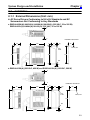
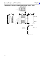
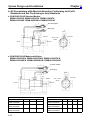
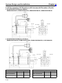
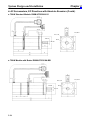
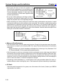
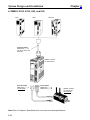
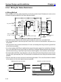
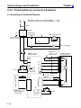
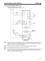
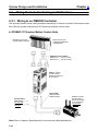
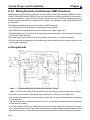
Chapter 2
System Design and Installation
2-2-5 Peripheral Device Connection Examples
H Connecting to Peripheral Devices
R
T
Single-phase, 200/230 VAC, 50/60 Hz (R88D-UjjjH(A))
Single-phase, 100/115 VAC, 50/60 Hz (R88D-UjjjL(A))
MCCB
1
E
3
2
NF
4
Noise filter
Main-circuit
power supply
Main-circuit connector
ON
OFF
1MC
Class-3 ground
(to 100 Ω or less)
1MC
Surge killer
X
X
1MC
PL
OMNUC U-series
AC Servo Driver
XB
OMNUC U-series
AC Servomotor
B
24VDC
R
U
T
V
CN1
X
R88D-CAUjjjS
(-CAUjjjB)
Power Cable
Servo error display
M
34 ALM
W
24 VDC
35 ALMCOM
Class-3 ground
(to 100 Ω or less)
User’s control device
X
CN1
CN2
R88A-CRUjjjC (Incremental)
R88A-CSUjjjC (Absolute)
Encoder Cable
E
CN1
R88A-CPUjjjS
General-purpose
Control Cable
2-38
BKIR 7
XB
24 VDC
OGND 10