1
LC-32LE631
LC-40LE631
LC-46LE631
Service Modes, Error Codes, and Fault Finding (continued)
•
•
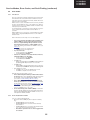
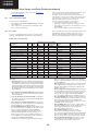
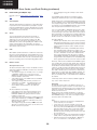
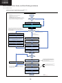
Contents of CSM
The contents are reduced to 3 pages: General, Software
versions and Quality items. The group names itself are not
shown anywhere in the CSM menu.
fit on the screen, move the “CURSOR UP/DOWN” key to
display the next/previous menu items.
With the “CURSOR LEFT/RIGHT” keys, it is possible to:
– (De) activate the selected menu item.
– (De) activate the selected sub menu.
With the “OK” key, it is possible to activate the selected
action.
General
Set Type. This information is very helpful for a helpdesk/
workshop as reference for further diagnosis. In this way, it
is not necessary for the customer to look at the rear of the
TV-set. Note that if an NVM is replaced or is initialized after
corruption, this set type has to be re-written to NVM. The
update can be done via the NVM editor available in SAM.
•
How to Exit SAM
Use one of the following methods:
• Switch the TV set to STAND-BY via the RC-transmitter.
• Via a standard RC-transmitter, key in “00” sequence, or
select the “BACK” key.
5.2.3
•
Production Code. Displays the production code (the serial
number) of the TV. Note that if an NVM is replaced or is
initialized after corruption, this production code has to be
re-written to NVM. The update can be done via the NVM
editor available in SAM.
•
Installed date. Indicates the date of the first installation of
the TV. This date is acquired via time extraction.
Options 1. Gives the option codes of option group 1 as set
in SAM (Service Alignment Mode).
Options 2. Gives the option codes of option group 2 as set
in SAM (Service Alignment Mode).
12NC SSB. Gives an identification of the SSB as stored in
NVM. Note that if an NVM is replaced or is initialized after
corruption, this identification number has to be re-written
to NVM. This identification number is the 12nc number of
the SSB.
12NC display. Shows the 12NC of the display.
12NC supply. Shows the 12NC of the power supply.
12NC 200Hz board. Shows the 12NC of the 200Hz Panel
(when present).
12NC AV PIP. Shows the 12NC of the AV PIP board
(when present).
Customer Service Mode (CSM)
Purpose
When a customer is having problems with his TV-set, he can
call his dealer or the Customer Helpdesk. The service
technician can then ask the customer to activate the CSM, in
order to identify the status of the set. Now, the service
technician can judge the severity of the complaint. In many
cases, he can advise the customer how to solve the problem,
or he can decide if it is necessary to visit the customer.
The CSM is a read only mode; therefore, modifications in this
mode are not possible.
•
•
•
When in this chassis CSM is activated, a test pattern will be
displayed during 5 seconds (1 second Blue, 1 second Green
and 1 second Red, then again 1 second Blue and 1 second
Green). This test pattern is generated by the PNX51X0
(located on the 200Hz board as part of the display). So if this
test pattern is shown, it could be determined that the back end
video chain (PNX51X0 and display) is working.For TV sets
without the PNX51X0 inside, every menu from CSM will be
used as check for the back end chain video.
•
•
•
•
Software versions
• Current main SW. Displays the build-in main software
version. In case of field problems related to software,
software can be upgraded. As this software is consumer
upgradeable, it will also be published on the Internet.
Example: Q55xx1.2.3.4
S5551_0.9.21.0
When CSM is activated and there is a USB stick connected to
the TV set, the software will dump the CSM content to the USB
stick. The file (CSM_model number_serial number.txt) will be
saved in the root of the USB stick. This info can be handy if no
information is displayed.
When in CSM mode (and a USB stick connected), pressing
“OK” will create an extended CSM dump file on the USB stick.
This file (Extended_CSM_model number_serial number.txt)
contains:
• The normal CSM dump information,
• All items (from SAM “load to USB”, but in readable format),
• Operating hours,
• Error codes,
• SW/HW event logs.
•
•
•
•
To have fast feedback from the field, a flashdump can be
requested by development. When in CSM, push the “red”
button and key in serial digits ‘2679’ (same keys to form the
word ‘COPY’ with a cellphone). A file “Dump_model
number_serial number.bin” will be written on the connected
USB device. This can take 1/2 minute, depending on the
quantity of data that needs to be dumped.
Stand-by SW. Displays the build-in stand-by processor
software version. Upgrading this software will be possible
via USB (see section 5.9 Software Upgrading)
STBY_89.167.00
Example: STDBY_83.84.0.0.
e-UM version. Displays the electronic user manual SWversion (12NC version number). Most significant number
here is the last digit.
AV PIP software.
3D dongle software version.
Quality items
• Signal quality. Bad / average /good (not for DVB-S).
• Ethernet MAC address. Displays the MAC address
present in the SSB.
• Wireless MAC address. Displays the wireless MAC
address to support the Wi-Fi functionality.
• BDS key. Indicates if the set is in the BDS status.
• CI module. Displays status if the common interface
module is detected.
• CI + protected service. Yes/No.
• Event counter :
S : 000X 0000(number of software recoveries : SW
EVENT-LOG #(reboots)
S : 0000 000X (number of software events : SW EVENTLOG #(events)
H : 000X 0000(number of hardware errors)
H : 0000 000X (number of hardware events : SW EVENTLOG #(events).
Also when CSM is activated, the LAYER 1 error is displayed via
blinking LED. Only the latest error is displayed (see also
section 5.5 Error Codes).
How to Activate CSM
Key in the code “123654” via the standard RC transmitter.
Note: Activation of the CSM is only possible if there is no (user)
menu on the screen!
How to Navigate
By means of the “CURSOR-DOWN/UP” knob on the RCtransmitter, can be navigated through the menus.
47