1
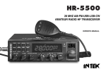
USER’S MANUAL
10 METER RADIO
SYMBOLS DESCRIPTION
Please carefully read the instructions
Information on recycling, not throwing your material in the trash at the end of life,
Bring it to special aera to be recycling
DC using
Keep dry
Shield symbol
CE conformity symbol
Alert symbol indicating an incomplete harmonization of the frequency band
which will result in restrictions on the use of the equipment concerned.
Warning
STORAGE , TRANSPORT, USING
Storage : Classe 1 -30/85% (° Humidity)
Transport :- 30/85% (° Humidity )
operating temperature –30 à + 50°
Using cycle TX 10%/RX 90%
This transceiver corresponds to the requirements of European directives R&TTE and answers the European
standards of telecommunication EN 60950-1, EN 301 489-1/-15 et EN 301 783-1/-2.
IMPORTANT : This receiving transmitter works on not free frequencies in the use. The user has to possess a
radio license amateur radio (certificate of radio operator HAM) to use it (in emission) and only on the frequencies
authorized in radio amateurs.
Thank you for choosing this CRT vehicle transceiver CRT always provides high quality products,Though friendly
design for user, this transceiver is technically complicated and some features may be new to you. Consider this
manual to be a personal tutorial from the designers, allow the manual to guide you through the learning process
now, then act as a reference in the coming years.
PRECAUTIONS
Please observe the following precautions to prevent fire, personal injury, or transceiver damage.
Do not attempt to configure your transceiver while driving, it is dangerous.
This transceiver is designed for a 13.8V DC power supply. Don’t use a 24V battery to power on the transceiver.
Do not place the transceiver in excessively dusty, humid or wet areas, nor unstable surfaces.
Do not connect the antenna while transmission, risk of burn or electric shock.
Please keep it away from interferential devices (such as TV, generator etc.) devices (such as TV, generator etc.)
For those fitted with pacemakers are advised to move away from the antenna during transmission, mainly in high
power, and especially do not touch it.
Never allow metal objects or son electrical contact with the part or internal electrical connection to the risk of
electric shock.
Avoid exposing the transceiver to temperatures below -30 ° C. and above +60 ° C, the temperature of the dashboard inside a vehicle can sometimes exceed 80 ° C, which can damage irreparable damage to your machine in
case of prolonged exposure. Not exposed to prolonged direct sunlight or place it near heaters.
Do not place anything on top of the apparatus that would interfere with cooling
Check that your battery is sufficiently charged to avoid rapidly exhausting its resources.
It is important to turn off your device before starting the vehicle to avoid damage caused by spikes in the ignition.
When replacing the fuse, you must use a fuse 10A 250V type F
In no case a higher value!, Otherwise a fire hazard.
If an abnormal odor or smoke is detected coming from the transceiver, turn OFF the power immediately.
Contact an CRT service station or your dealer.
Do not transmit with high output power for extended periods; the transceiver may overheat.
Keep out from children.
Attention:
• Before using your transceiver please connect an antenna on the connector PL on back side then check the
SWR before emitting. A too important SWR can entail the destruction of the transistors of power which are not
flatware by the guarantee
WELCOME TO USE
Welcome to the world of new CB radios. The new SS 6900 Radio provides you with top performance and best visual
enjoyment. With the use of SMT technology to guarantee the best stability, reliability and unprecedented quality, your
multi-functional SS 6900 Radio 10-meter Radio is a new step in personal communication and is surely the best choice for
professional users of CB radios. Moreover, with multiple connecting ports in the radio, SS 6900 Radio is ready for future
upgrading and functions expanding. To ensure that you use the radio to the fullest, please read this manual carefully
before installing and using your SS 6900 Radio.
CONTENTS
FUNCTIONS & FEATURES ...............................................................................................................................................................1
WARNING ..........................................................................................................................................................................................1
RESET FUNCTION (Resume Factory Default) ...............................................................................................................................1
INSTALLATION ..................................................................................................................................................................................2
RADIO…...
HOW TO USE YOUR CB
RADIO ......................................................................................................................................................4
FUNCTION MENU SETUP ................................................................................................................................................................8
OPERATING PROCEDURE TO RECEIVE ........................................................................................................................................11
OPERATING PROCEDURE TO TRANSMIT .....................................................................................................................................11
SPECIFICATIONS..............................................................................................................................................................................12
PROGRAMMING BY COMPUTER (OPTION)............................................................................................................................12
FUNCTIONS & FEATURES
Big LCD which displays frequency and all kinds of information
DUAL-DIGITAL TUBE FOR CHANNEL DISPLAY
USE EL technology for backlight
PA、CW、AM、FM、USB、LSB mode
A、B、C、D、E、F , 6 bands in total, with 60 channels at most in
each band to be programmed.
61 Frequency Tuning Step can be 10HZ, 100HZ, 1KHZ or 10KHZ.
71 Multiple CLARIFIER Operating Modes
81 Flexible menu functions and PC programming software to meet
varied customer demands
91 ECHO Function
111 SQ, ASQ Function (FM and AM mode only)
111 RF GANI
GAIN ADJUSTMENT
121 RF PWR ADJUSTMENT
131 SCAN FUNCTION
141 RB FUNCTION
151 NB/ANL FUNCTION
161 DW DUAL-WATCH FUNCTION
171 BEEP VOICE PROMPT
181 +10KHZ Function
191 SWR、S/RF、DC Voltage display function
211 TOT function
211 HI-CUT FUNCTION
221 EMG CALL
231 SWR PROTECTION
241 POWER SUPPLIED VOLTAGE PROTACTION
251 Key-Lock Function
11
21
31
41
51
1
WARNIGN
To use the radio, please connect the antenna to the location "B" on the
back panel of the equipment firstly and then set the SWR (Standing
Wave Ratio) before transmitting. Failure to do so may result in
destruction of the power amplifier, which is not covered by the guarantee.
RESET FUNCTION (Resume Factory Default)
This CB Radio introduces RESET FUNCTION to prevent accidents
and provide a solution for customers who changed some functions
unconsciously and do not know how to resume normal settings. The CB
Radio will resume factory default once this function is activated.
How to Operate:
Step 1: Power off the radio.
Step 2: Press and hold FUNC and SCAN keys at the same time,
followed by powering on the radio.
Step3: Release the two keys when LCD displays "RES".
All former settings would be replaced by Factory Default value when
LCD displays "REND" .
WARNING: All former settings would be replaced by Factory Default
value after operating the RESET FUNCTION.
INSTALLLATON
11 WHERE AND HOW TO MOUNT YOUR MOBILE CB RADIO
a)You should choose the most appropriate setting from a simple and
practical point of view.
b)Your CB radio should not interfere with the driver or the passengers.
c) Remember to provide different wires for passing and protection.
(e.g.: power, antenna, accessory cabling) so that they do not in any
way interfere with the driving of vehicles.
d)To install your equipment, use the cradle (1) and the self-tapping
screws [2] provided (drilling diameter 5 mm). Take care not to
damage the vehicle’s electrical system while drilling the dash
board.
e)Do not forget to insert the rubber joints [3] between the CB
TX and
its support as these have a shock-absorbing effect which permits
gentle orientation and tightening of the set.
f)Choose where to place the microphone support and remember that
the microphone cord must stretch to the driver without interfering
with the controls of the vehicle.
21 ANTENNA INSTALLATION
a) Choosing your antenna:
For CB radios, the longer the antenna, the better its results. Your
dealer will help you with your choice of antenna.b) Antena Movel.
b) Mobile antenna:
-Must be fixed to the vehicle where there is a maximum of metallic
surface(ground plane) , away from windscreen mountings.
-There are two types of antenna: Pre-Regulated Antenna which
should be used on a good ground plane (e.g. car roof or lid of the
boot), and Adjustable Antenna which offer a much larger frequency
range and can be used on a smaller ground plane.
For an antenna which must be fixed by drilling, you will need a
good contact between the antenna and the ground plane. To obtain
this, you should lightly scratch the surface where the screw and
tightening star are to be placed.
-Be careful not to pinch or flatten the coaxial cable (as this runs the
risk of break down and/or short circuiting).
2
-Connect the antenna to location (B).
c) Fixed antenna:
A fixed antenna should be installed in a space as clear as possible.
If it is fixed to a mast, it will perhaps be necessary to stay it,
according to the laws in force (you should seek professional
advice). All SS 6900 antennas and accessories are designed to
give maximum efficiency to each CB radio within the range.
31 POWER CONNECTION
Your RADIO is protected against an inversion of polarities. However,
before switching it on, you are advised to check all the connections.
Your equipment must be supplied with a continued current of 12
volts (A). Today, most cars and lorries are negative earth. You can
check this by making sure that the negative terminal of the battery is
connected either to the engine block or to the chassis. If this is not the
case, you should consult your dealer.
3
WARNING: Lorries generally have two batteries to supply a voltage
of 24 volts, in which case it will be necessary to insert a 24/12 volt
converter into the electrical circuit. The following connection steps
should be carried out with the power cable disconnected from the set.
a)Check whether the battery is of 12 volts.
b)Locate the positive and negative terminals of the battery (+ is red
and – is black). Should it be necessary to lengthen the power
cable, please use the same or a superior type of cable.
c)It is necessary to connect your TX
CB to a permanent (+) and (-). We
advise you to connect the power cable directly to the battery (as
the connection of the TX
CB cable to the wiring of the car-radio or
other parts of the electrical circuit may, in some cases, increase
the possibilities of interference).
d)Connect the red wire (+) to the positive terminal of the battery
and the black (-) wire to the negative terminal of the battery.
e)Connect the power cable to your CB radio.
WARNING: Never replace the original fuse (10A) by one of a different
value.
Connected
to chassis
41 BASIC OPERATIONS TO BE CARRIED OUT BEFORE USING
YOUR SET FOR THE FIRST TIME (without transmitting or using
the <<Push-To-Talk>> switch on the microphone)
a) Connect the microphone
b) Check the antenna connections
c) Turn the set on by turning the volume knob clockwise
d) Turn the squelch knob to minimum
e) Adjust the volume to a comfortable level
f) Go to channel 20@D band by using either the UP or DN key on
the microphone or the rotary knob.
51 ADJUSTMENT OF SWR(standing wave ratio)
WARNING: This must be carried out when you use your CB radio
for the first time (and whenever you re-position your antenna). The
adjustment must be carried out in an obstacle-free area.
Adjustment with a built-in SWR meter or external SWR meter
a) To connect the SWR meter
Connect the SWR meter between the CB radio and the antenna
as close as possible to the CB radio (use a maximum of 40cm
cable).
b) To adjust the SWR meter
-Set the TX
CB to channel 20@D band in FM.
-put the switch on the SWR meter to position CAL or FWD.
-Press the <<Push-To-Talk>> switch on the microphone to
transmit.
-Bring the index needle to ▼ by using the calibration key.
- Change the switch to position SWR (reading of the SWR level).
The reading on the meter should be as near as possible to 1. If
this is not the case, re-adjust your antenna to obtain a reading
as close as possible to 1.( An SWR reading between 1 and 1.8 is
acceptable).
-It will be necessary to re-calibrate the SWR meter after each
adjustment of the antenna.
61 HOW TO USE INTERNAL SWR METER
as close as possible to 1.( An SWR reading between 1 and 1.8 is
acceptable).
-It will be necessary to re-calibrate the SWR meter after each
adjustment of the antenna.
61 -Set
HOW
INTERNAL
SWRinMETER
CBTO
to USE
channel
20@D band
FM.
-Set
CB
to
channel
20@D
band
in FM.
TX
-Press <<push-to-talk>> button on
the microphone to transmit.
-Press
button
on the
microphone
to transmit.
-At the <<push-to-talk>>
moment, LCD would
display
SWR
value which
should be
as close
as possible
1. If display
this is not
the
case,
re-adjust
your
-At
the moment,
LCD to
would
SWR
value
which
should
be
antenna
a SWR
asnot
close
possible
to 1your
(an
as
close to
as obtain
possible
to 1. Ifvalue
this is
the as
case,
re-adjust
SWR reading
between
1 and
1.8 isasacceptable).
antenna
to obtain
a SWR
value
close as possible to 1 (an
SWR reading between 1 and 1.8 is acceptable).
HOW TO USE YOUR CB RADIO
HOW TO USE YOUR CB RADIO
<LCD Display>
<LCD Display>
7 digits: Display frequency and any other information.
7
digits: Display
and
any other
information.
Indicating
bars: frequency
Indicate RX,
RSSI,
PA, PWR,
SWR.
Indicating
bars: Indicate
RX, RSSI,
PA,current
PWR, SWR.
The first decimal
point: Appears
when
channel is edited with
The
first
decimal point: Appears when current channel is edited with
SCAN
DEL.
SCAN
DEL.
FUNC:Appears
after pressing FUNC key.
FUNC:Appears
after
pressing
FUNC
key. (only for AM/FM).
AQ:Appears when
ASQ
function
is started
AQ:Appears
ASQ function
is started
(only for
AM/FM).
RB:Appears when Roger
beep function
is started
(enabled).
RB:Appears
when when
RogerNB/ANL
beep function
is is
started
(enabled).
NB/ANL: Appears
function
started
(enabled).
NB/ANL:
Appears
NB/ANL
function(enabled).
is started (enabled).
BP:Appears
when when
BP function
is started
BP:Appears
when
BP function
is started
(enabled).
ECHO: Appears
when
ECHO function
is started
(enabled).
ECHO:
Appearswhen
whenVOIC
ECHO
functionis isstarted.
startedIt(enabled).
VOIC: Appears
function
is disabled in this CB
radio. Appears when VOIC function is started. It is disabled in this CB
VOIC:
radio.
HI-CUT:Appears when HI-CUT function is started.
HI-CUT:Appears
when
is started.
DW: Appears when
DWHI-CUT
function function
is started.
DW: Appears when DW function is started.
10K: Appears when +10KHZ function is started.
10K:
function
started.
EMG:Appears
Appearswhen
when+10KHZ
EMG channel
is is
used.
EMG:
SWR: Appears when EMG
SWR channel
is used. is used.
SWR:
Appearswhen
whenS/RF
SWRisisused.
used.
SRF: Appears
SRF:
Appearswhen
whenSCAN
S/RF is
is used.
used.
SC: Appears
SC:
Appears when SCAN is used. Indicate different operating modes.
PA、CW、AM、FM、USB、LSB:
PA、CW、AM、FM、USB、LSB:
Indicate
different
operating modes.
11 Appears when CLARIFIER function
is FINE
operation.
21
11
21
31
31
Appears when
when CLARIFIER
CLARIFIERfunction
FUNCTION
is operation.
COARSE operation or
is FINE
RT operation.
Appears
when CLARIFIER FUNCTION is COARSE operation or
Appears
when CLARIFIER FUNCTION is transmitting frequency
RT
operation.
regulated.when CLARIFIER FUNCTION is transmitting frequency
Appears
regulated.
4
4
<FRONT PANEL>
<FRONT
PANEL>
11 OFF/ON/VOLUME(Inner
Dual Concentric)
11
OFF/ON/VOLUME(Inner
Dual
Turn
clockwise to switch on the
CBConcentric)
radio and set desired volume level.
Underclockwise
normal operating
state,
control
is used
to adjust
Turn
to switch on
the the
CB VOLUME
radio and set
desired
volume
level.
the output
volume
obtained
either
by the transceiver
the
Under
normal
operating
state,
the VOLUME
control is speaker
used to or
adjust
external
speaker
or obtained
the external
PA speaker,
if used. speaker or the
the
output
volume
either
by the transceiver
external
speaker
or theDual
external
PA speaker, if used.
21
SQUELCH
(Outer
Concentric)
21 SQUELCH
(Outer
This
control is used
to Dual
cut offConcentric)
or eliminate receiver background noise in
the absence
an incoming
For maximum
receiver sensitivity,
This
control isofused
to cut off signal.
or eliminate
receiver background
noise in
the absence of an incoming signal. For maximum receiver sensitivity,
it is desired that the control be adjusted only to the point where the
receiver background noise or ambient background noise is eliminated.
Turn fully anticlockwise then slowly clockwise until the receiver noise
disappears. Any signal to be received must now be slightly stronger
than the average received noise. Further clockwise rotation will
increase the threshold level which a signal must overcome in order to
be heard. Only strong signals will be heard at a maximum clockwise
setting.
31 ECHO(Inner Dual Concentric)
This switch is used to control echo effect.
5
41 TONE (Outer Dual Concentric)
This switch is used to control intervals of echo sound
51 RG GAIN ( Inner Dual Concentric)
This switch is for adjusting sensitivity during reception. For long
distance communications RF GAIN should be set to maximum. RF
GAIN can be reduced to avoid distortion, when your correspondent is
close by and when he does not have RF POWER. The normal setting
of this function is on maximum (fully clockwise).
61 RF POWER (Outer Dual Concentric)
Adjustment of the output power is for AM and FM mode only. Reducing
the power is allowed when communicating with a person who has no
RF GAIN. The normal position of this function is set to maximum, fully
clockwise.
71 BAND SELECTOR
Rotate this switch to select A, B, C, D, E, F band of operation
81 MODE(PA/CW/AM/FM/USB/LSB)
This switch allows selecting the modulation mode PA, CW, AM, FM,
LSB or USB. Your modulation mode has to correspond with the one
of your correspondent. The mode selector changes the mode of
operation of both transmitter and receiver simultaneously.
Frequency Modulation/FM: for nearby communications on a flat
open field.
Amplitude Modulation/AM: Communication on a field with relief and
obstacles in middle distance (the most used).
Upper and Lower Side Band/USB-LSB: Used for long distance
communications (according to the propagation conditions).
91 CLARIFIER
This is frequency tuning knob which can be set as different modes
(refer to CLA Specifications in Functions Menu for more details).
111 PUSH
This is PUSH Key which can be set as different modes (refer to PSH
specifications under Functions Menu for more details).
111 CHANNEL SELECTOR
Rotate this switch to select any desired channel from forty citizens
band channels. The selected channel appears on the LED directly
above the channel selector knob.
121 CHANNEL INDICATOR
Numbered LED indicates the selected channel to operate on.
131 RECEIVER/TRANSMIT INDICATOR
When it is receiving, the LED will be green. The LED will be red when
it is transmitting.
141 LCD DISPLAY
Display frequency, all kinds of information and icons.
151 FUNC
This is functional key. Press and hold this key for 2seconds to enter
into Functions Menu Setup (refer to Functions Menu for more details).
Press FUNC key and other individual key to realize the second
functions silk-screened under the button. For example, press FUNC
key followed by pressing RB key to realize the BP function. Press
FUNC key followed by DW to realize the LCD OFF function.
Details operations are as bellows:
Press FUNC key, "FUNC" icon will appear on LCD display. Release
FUNC key, and then press other keys to realize the second functions
silk-screened under the button. "FUNC+ Keypad name" is to be used
in the following operating instruction.
161 ROGER BEEP OR BEEP FUNCTION
(1)RB
Press "RB" key to enable "ROGER BEEP" function with "RB" icon
appearing on LCD display. Press the key repeatedly to switch on/off
the function.
When RB function is enabled, the radio will automatically transmit the
audio signal at the end of your transmission. The listener can note
easily that your transmission is over through the signal.
(2)FUNC+RB
Press FUNC+RB to realize BP Function. It is a prompting function with
"BP" icon appearing on LCD display. Speaker would emit a BEEP for
prompting when press any key. press FUNC+RB repeatedly to switch
on/off the function.
171 NB/ANL or LOCK
(1)Press NB/ANL key to enable NB/ANL function with "NB/ANL" icon
appearing on the LCD display. Press the key repeatedly to switch on/
off the function.
Noise Blanker/Automatic Noise Limiter. These filters allow reducing
back ground noises and some reception interferences.
(2)FUNC+NB/ANL
Press FUNC+NB/ANL to realize the Keyboard Lock function. When
this function is enabled, all keys are invalid except PTT, BAND
SWITCH, and MODE SWITCH. When pressing any key except PTT,
BAND SWITCH, MODE SWITCH, the LOCK icon will display on the
LCD. These situations indicate that the keyboard has been locked.
Press FUNC+NB/ANL repeatedly to switch on/off the function.
181 DW or LCD OFF
(1)The DW (dual watch) function allows automatic alternate
monitoring of two channels. Refer to the following procedures to
enable this function.
To enable the DW function, firstly turn the SQ control clockwise
until the background noise is cut out. Select the first channel to be
monitored by using the CHANNEL SELECTOR knob or the channel
selector keys on the microphone. Press the DW key and the DW icon
will flash on the LCD display. Secondly, follow the above procedures
to select second channel to be monitored. Finally, press the DW key
again and the two monitoring channels will be alternately indicated on
the LCD. Radio will automatically start monitoring (scanning) the two
channels. When a signal is detected on one of the channels, scanning
stops and it is possible to listen the communications on that channel.
Press PTT to transmit on this channel. If there is no transmission
or detected signal on that channel within 5 seconds(time to resume
scanning can be programmed by PC software), radio will resume
scanning. When the DW function is enabled, the DW icon appears on
the LCD. To exit the DW function, press the DW key or the PTT key.
The scan Type above is the SQ mode under SCA Selection in
Function Menu. If TI mode is selected and valid signal is detected, the 6
radio would still start scanning when it is time to resume scanning,
whether there is signal or not in current channel.
(2)FUNC+DW
When this function is enabled, LCD display would be switched
OFF(LCD OFF).
Repeat this operation to switch ON/ OFF the function.
191 SCAN OR Scan.list
(1)SCAN
Automatic Scanning of busy channels.
Press the SCAN key to enable the SCAN function. Before enabling the
SCAN function, firstly turn the SQ control clockwise till the background
noise is cut out. Then press the SCAN key, radio will automatically
scan all channels continuously in the scan list and the SC icon will
appear on the LCD.
When a signal is detected on a channel, scanning stops on this
channel. You can receive the calling, and also, can transmit on this
channel by pressing PTT key. If there is no transmission or detected
signal on that channel within 5 seconds(time to resume scanning can
be programmed by PC software), radio will start scanning again. To
exit the SCAN function, press the SCAN key or the PTT key.
The Scan Type above is the SQ mode under SCA Selection in
Function Menu. If TI mode is selected and valid signal is detected, the
radio would still start scanning when it is time to resume scanning,
whether there is signal or not in current channel.
(2)FUNC+SCAN
SC.LIST (Scan ADD or Delete). Press FUNC+SCAN to delete current
channel from scan list. The first digit on LCD would display. When
Scan function is enabled, the radio would skip the deleted channel.
Repeat this operation to Add or Delete channels from scan list.
211 +10KHZ or HI-CUT
7
(1)+10KHZ Press this key to shift frequency up by 10khz.
When pressing this key, 10KHZ would appear on LCD and frequency
of channels is shifted up by 10 KHZ. Repeat this operation to switch
ON/OFF this function.
(2)FUNC+ +10KHZ
Press FUNC+10KHZ to realize HI-CUT function. Once this function is
enabled, the radio would cut out high frequency interference. Its use
depends on reception conditions.
When this function is enabled, "HI-CUT" would appear on LCD. Repeat
this operation to switch ON/OFF the function
211 SWR OR TOT
(1)SWR
When pressing this key, “SWR” icon would appear on the LCD. When
transmitting, SRF bars indicate SWR value other than PA or PWR
value. One bar displaying on the LCD indicates that SWR value is
1.0. Each additional bar indicates every 0.1 added value. Repeat this
operation to switch ON/OFF the function.
(2)FUNC+ SWR
When pressing this key, TOT ON or TOT OFF would display on the
LCD for 2 seconds. Repeat this operation to switch ON/OFF the
function. When ON appears on the LCD, users can press PTT to
transmit. Then, the radio would time the transmitting duration. Once
the duration is beyond the set TOT time (programmable), the radio
would emit voice prompt and stop transmitting and back to receiving
state automatically. This function aims to protect the radio against
power tube damage from superheating caused by long transmission.
221 EMG OR S/RF
(1)EMG realizes Emergency Channel Call. When emergent situation
happens, the radio would switch to the channel set in advance to
communicate immediately. Then the "EMG" icon would display on the
LCD . Press EMG key again to return to previous channel.
(2)FUNC + S/RF
S/RF is the switch of TX's or RX's S/RS indicating bar. When this
function is enabled, "SRF"icon would display on the LCD. Repeat the
this operation to switch ON/OFF the function.
<Rear Panel>
231 POWER
Accept13.8V DC power cable with built-in fuse (10 Amp) to be
connected.
241 EXT SP or PA SP
EXT SP
Accept 4 to 8 ohm, 4 watt external speaker to be connected. When
external speaker is connected to this jack, the built-in speaker is
automatically disconnected.
PA SP
It is used to connect a PA speaker. Before operating PA, you must
firstly connect a PA speaker to this jack.
251 ATTENNA
Accept 50 ohm coaxial cable with a type PL-259 plug to be connected.
261 CW KEY
This jack is for Morse code operation; To operate, connect a CW
key to this jack and place the MODE switch in the CW position (LCD
display icon "CW")
<PRESS—TO—TALK—MICROPHONE>
The receiver and transmitter are controlled by the Press-To-Talk
switch on the microphone.
Press the switch to transmit and then release it to receive. When
transmitting, hold the microphone two inches from the mouth and
speak clearly in a normal “voice”. The radios come complete with lowimpedance (150 ohm) dynamic microphone.
11 PTT
Transmitting key, Press to speak and release to receive a message.
21 UP/DN
These key allow increasing or decreasing a channel number.
31 AQ
(1)When the radio is receiving a call, press this key to enable ASQ
(Automatic Squelch Control) function. Then, "AQ" would appear on the
LCD. Press this key repeatedly to switch on/off the function.
(2)When the radio is receiving a call, press and hold this key for
over 2 seconds to enable signal monitoring function. At the moment,
whether the radio receive signal or not, the radio would detect current
channel to check whether current channel has weak signal.Release
AQ key to exit this function.
(3)Pressing PTT and AQ key at the same time, the radio would
emit a single-tone. This tone is to help and remind two sides of
communication to adjust frequency. The frequency of this tone is
adjustable.
8
(4)ASQ (Automatic Squelch Control)
ASQ control setting.It has same function with AQ button on the
microphone.
41 MICROPHONE
The radios come complete with low-impedance (150 ohm) dynamic
microphone.
FUNCTION MENU SETUP
The initial functions and parameter can be changed via the following
settings and operations. Please read the following instruction before
making any desired amendments.
To enter Function Menu: under ON state, press and hold FUNC key for
more than 2seconds, and then release the FUNC key to enter into the
Function Menu Setup. Under this condition, press FUNC key to select
different functions menu, CHANNEL SELECTOR Switches to change
the data of Function Menu.
(1) STP (Frequency Tuning Step)
This menu is to set tuning step when adjusting frequency by
CLARIFIER knob
Options: 10HZ、100HZ、1KHZ、10KHZ
Default: 10HZ
(2) CLA (CLARIFIER knob functions setting)
9
This menu is to set functions turned by CLARIFIER knob. Options are
as follows:
FIN: Fine regulation. When this option is selected, users can fine
tuning the receiving frequency by rotating the CLARIFIER
knob. In tuning process, the transmitting frequency can not be
regulated by the knob and “1” icon will appear on the LCD.
RT: When this option is selected, users can regulate the frequency of
both transmitting and receiving. In tuning process, “2” icon will
appear on the LCD.
T: When this option is selected, users can only regulate the
transmitting frequency. In tuning process, “3” icon will appear on
the LCD.
Default: RT
(3) PUS (PUSH Function Setting)
This menu is to set functions realized via PUSH knob. Options are as
follows:
COA: When this option is selected, press PUSH and turn CLARIFIER
knob to realize COARSE function.
When pressing this key, "2" icon will appear on far left of the
LCD. Under this condition, rotate the CLARIFIER knob to change
frequency of both transmitting and receiving.
T: When this option is selected, press PUSH and turn CLARIFIER
knob to change transmitting frequency. When pressing this key,
"3" icon will display on the far left of the LCD. Under this condition,
rotate the CLARIFIER knob to change the transmitting frequency
only.
STP:When this option is selected, PUSH function will change
Frequency Tuning Step of CLARIFIER knob. Press this key, then
the corresponding frequency bit would blink.
Default: STP
(4) ASQ (Automatic Squelch Control)
ASQ control setting. It has same function with AQ button on the
microphone.
Default: OFF
(5)TOT (Transmitting Time-Out-Timer)
This menu is to set transmitting TOT time. When pressing PTT key
at a single time longer than the due time setup in advance, the radio
would stop transmitting automatically and loudspeaker will emit voice
prompt till PTT key is released. Then, the radio can transmit again.
Options: 30-600s Step: 30s
Default: 180s
(6) SC Scanning Type Selection
This menu is to set Scan Type. Options are as follows:
SQ: When SQ is selected, scan would stop when a valid signal
is detected. The radio would resume scanning after signal
disappears for 5s.
TI: When TI is selected, scan would stop when a valid signal is
detected. The radio would resume scanning 5 seconds later,
whether signal disappears or not.
Default: SQ
This menu is to choose whether to enable Power supplied Voltage
Protection function or not.
ON: When ON is selected, the radio will detect the supplied voltage.
Once the voltage surpasses the voltage setup in advance, the
radio would display “DC LO” or “DC HI” to remind you that the
voltage is not in normal state. Meanwhile, the radio will prohibit
transmitting and emit beep prompt.
OFF: When OFF is selected, the Power Supplying Voltage is disabled.
Default: ON (DC 10.5V-16V)
(7) TSR (Transmitting SWR Protection)
(9) TLD (Content displayed on the LCD when transmitting)
This menu is to choose whether to enable Transmitting SWR
Protection function or not.
ON: When ON is selected, the radio will detect the SWR of antenna.
Once the SWR is beyond the SWR set in advance, the radio
would prohibit transmitting automatically and loudspeaker will
emit voice prompt. Then, “HI S” icon will display on the LCD to
remind you that the antenna SWR is too high or antenna do not
connect well.
OFF: When OFF is selected, SWR Protection function is disabled.
NOTE: To protect the radio from long transmission under high SWR,
the radio would automatically start SWR Protection once the
SWR Value is higher than 20:1.
Default: ON (SWR=<10:1)
(8) TDC (Power Supplied Voltage Protection)
This menu is to set the content displayed on the LCD when
transmitting.
TF: W h e n T F i s s e l e c t e d , L C D w o u l d d i s p l a y t r a n s m i t t i n g
frequency when transmitting.
SR: When SR is selected, LCD would display SWR value of antenna
when transmitting, for example: "1.2" on the LCD.
BAT: When BAT is selected, LCD would display Supplied Voltage
when transmitting, for example: "13.8DC" on the LCD.
TOT: When TOT is selected, LCD would display TOT remaining time
when transmitting. And TOT would count down till remaining time
is 0, for example: "170" displayed on the LCD display.
Default: TF
(10) RBF (ROGER BEEP Frequency Setting)
10
This menu is to select frequency of Roger Beep. The frequency range
is 300KHZ—3KHZ. The shift step is 10HZ.
Default: 1050HZ
(11) RBT (ROGER BEEP Holding Time)
This menu is to select Roger Beep Holding Time from 50ms—1000ms.
The shift step is 50ms.
Default: 500ms
(12) CFR (CW Side Tone Frequency)
11
This menu is to select CW Side Tone Frequency from 300HZ-3KHZ,
the shift step is 10HZ.
Default: 1050HZ
(13) TON (Transmitting Single-Tone Frequency)
This menu is to select Transmitting Single-Tone Frequency from
300HZ-3KHZ. The shift step is 10HZ.
Default: 1050HZ
(14) TX MON
This menu is to set Talkback Monitoring Volume for voice message
sent.
TES: Under transmitting state and ECHO effect is ON, users can hear
their own voice in the radio they are using when TES is ON. You
can switch on or off this function via
CLARIFIER selector.
Default: ON
TNS: Under transmitting state and the ECHO function is OFF, users
can hear their own voice in the radio they are using when TNS
is ON. You can switch on or off this
function via CLARIFIER selector.
Default: OFF
OPERATING PROCEDURE TO RECEIVE
11 Be sure that power supply, microphone and antenna are
connected to the proper connectors before going to the next
step.
21 Turn the radio on by tuning VOLUME control clockwise.
31 Rotate the VOLUME knob to set a comfortable listening level.
41 SET the MODE switch to the desired mode.
51 Set the CHANNEL selector switch to select the desired channel.
61 Set the RF gain control full clockwise to maximum RF gain.
71 Listen to the background noise from the speaker. Turn the
SQUELCH control clockwise slowly until the noise disappears (no
signal should be present). Leave the control at this setting. The
Squelch is now properly adjusted. The receiver will remain quiet
until a signal is actually received. Do not advance the control too
far, or some of the weaker signals can not be heard.
OPERATING PROCEDURE TO TRANSMIT
11 Select the desired channel of transmission.
21 Press the Push-To-Talk switch on the microphone and speak in a
normal voice.
SPECIFICATIONS
General
Frequency Range
Frequency Band
Channel
Frequency Control
Frequency Step
Frequency Tolerance
Frequency Stability
Temperature Range
Microphone
Input Voltage
Size
Weight
Antenna Connector
28.000
29.700
25.615MHZ—30.105MHZ
(Programmable)
A/B/C/D/E/F
60 channels (programmable) in each band
Phase-Locked-Loop Synthesizer
10Hz 100Hz 1KHz 10KHz
0.005%
0.001%
-30℃to +50℃
Plug-in dynamic; with push-to-talk /UP/DN/
ASQ switch and coiled cord
DC 13.8V normal, 15.9V max; 11.7V
min Transmit: AM full mod 5A Receiver:
Squelched 0.6A SSB 21W PEP output 6A
28*25*6CM
2.8KG
UHF,SO239
TRANSMITTER
Power Output
Modulation
Inter-modulation
Distortion
SSB Carrier Suppression
Unwanted Sideband
Frequency Response
Saida Impedancia
AM/FM/CW: 12W
SSB:21W(PEP)
High and low level class B
Amplitude Modulation: AM
Varied Capacitance Frequency Modulation:
FM
SSB: 3rd order, more than -25dB; 5th
order, more than -35dB
55dB
50dB
AM and FM: 450 to 2500HZ
50ohms, unbalanced
Sensitivity
Selectivity
Image Rejection
IF Frequency
Adjacent-Channel
Rejection
RF Gain Control
Automatic Gain
Control(AGC)
Squelch
ANL
Noise Blanker
Audio Output Power
Frequency Response
Built-in Speaker
External Speaker(Not
Supplied)
SSB: 0.25μV for 10dB(S+N)/N at greater
than 1/2-watt of audio output.
AM:1.0μV for 10 dB(S+N)/N at greater
than 1/2watt of audio output.
FM: 1.0 μV for 20 dB (S+N)/N at greater
than 1/2 watt of audio output.
AM/FM:6dB@3KHz,50dB @9KHz
SSB: 6 [email protected],60dB @3.3KHz
More than 65dB
AM/FM: 10.695 MHz 1st IF, 455 KHz 2nd IF
SSB: 10.695 MHz
60dB AM/FM &70 dB SSB
45 dB adjustable for optimum signal
reception
Less than 10 dB change in audio output
for inputs from 10 to 100,000 microvolt.
Adjustable; threshold less than 0.5 μV.
Automatic Squelch Control(only AM/FM)
0.5 μV
Switchable
RF type, effective on AM/FM and SSB
4 watts into 8 ohms
300 to 2800 Hz
8 ohms, round.
8 ohms; disables internal speaker when
connected.
12
Programming by computer (OPTION) :
Use the software CRT SS 6900 and the software cable PC-50
(reference TX 000008) - the connection of the cable is made
inside the set (confirmed user)
DECLARATION OF CONFORMITY
We hereby declare under our responsability that the product :
Description : mobile transceiver HF amateur radio
Brand : CRT
Model : SS 6900
E
C
N
satisfies all the technical regulations applicable to the product within the scope of
directive R .TTE 1999/5/CE and 89/336/EEC european standarts
A
FR
EN 60950-1
EN 301 489-1/-15
EN 301 783-1/-2
The HAM version was approved in the CEPT countries and those non CEPT countries
that implement the CEPT regulation TR 61/01
T
R
C
CEPT Countries Codes : ALB-AND-AUT-AZE-BLR-BEL-BIH-BUL-HRV-CYP-CZE-DNK-EST-FIN-F-GEO-D-GRC-HNGISL-IRL-I-LVA-LIE-LTU-LUX-MKD-MLT-MDA-MCO-MNE-HOL-NOR-POL-POR-ROU-RUS-SMR-SRB-SVK-SVN-E-S-SUITUR-UKR-G-CVA
Mr CELESTRANO PHILIPPE
Manager
C.R.T. FRANCE INTERNATIONAL S.A.R.L. Route de Pagny - 21250 SEURRE - FRANCE
Capital de 762 500 euros
Tél. 03 80 26 91 91 - Fax : 03 80 26 91 00
E-mail : [email protected]
Web site : www.crtfrance.com
LE 05/12/2010