1
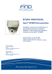
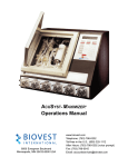
® BelloCell High-Density, Disposable Cell Culture System MANUAL NO: WISA0101 Revision 2.0 Feb 14, 2008 TA B L E O F C O N T E N T S p 1. SAFETY INFORMATION ……………………..………………………... 1 2. PRODUCT SPECIFICATION ……………………………………..…….. 2 3. SYSTEM DESCRIPTION ………………………….……………………. 4 4. CONTROL BOX FEATURES …………………………………….…… 5 5. BELLOCELL® 500 BOTTLE FEATURES ……….……………………... 6 6. BELLOCELL® 500P BOTTLE FEATURES ……….……………………. 7 7. BELLOCELL® 500 & BELLOSTAGE® 3000 DIMENSIONS ………….. 8 8. UNPACKING & INSTALLATION …………………………………….... 9 9. IMPORTANT CAUTIONS & WARNINGS …………………………..…11 10. OPERATION ……………………………………………………………12 10.1 General Instruction of BelloStage……………..…………………….....12 10.2 Running a Culture………………………………………….…………..15 10.3 Cell Harvest and Sampling ……………………...………………..…22 11. MAINTENANCE. ………………………………………………………28 12. TROUBLING SHOOTING ……………………………………….……29 13. QUESTION AND ANSWER …………………………….…………..…30 14. REFERENCE GUIDE ……………………….……...………………..…32 CESCO BIOENGINEERING CO., LTD. th 36, 20 Rd., Taichung Industry Park, Taichung, Taiwan, R.O.C. Telephone: +886-3-5910121 • Fax: +886-3-591-0123 • Internet: http://www.cescobio.com • E-mail: [email protected] ii http://www.cescobio.com.tw Copyright Notice CESCO Bioengineering Co., Ltd. 36, 20th Rd., Taichung Industry Park, Taichung, Taiwan, R.O.C. Copyright 2008 CESCO Bioengineering Co., Ltd. All Rights Reserved. Reproduction, adaptation, or translation without prior written permission from CESCO Bioengineering is prohibited. The information contained herein is designed only for use with this product. CESCO Bioengineering is not responsible for any use of this information as applied to other products. Neither CESCO Bioengineering nor its affiliates shall be liable to the purchaser of this product or third parties for damages, losses, costs, or expenses incurred by the purchaser or third parties as a result of accident, misuse, or abuse of this product or unauthorized modifications, repairs, or alterations to this product, or failure to strictly comply with maintenance instructions. Disclaimer Notice CESCO Bioengineering Co., Ltd. reserves the right to change information in this document without notice. Updates to information in this document reflect our commitment to continuing product development and improvement. Manual Conventions Bold Text in bold face type emphasizes key words or phrases. NOTE: CAUTION! WARNING! BIOHAZARD WARNING! CESCO Bioengineering Notes contain essential information that deserves special attention. Caution messages appear before procedures which, if caution is not observed, could result in damage to the equipment. Warning messages alert you to specific procedures or practices which, if not followed correctly, could result in serious personal injury. Biohazard Warnings alert you to user responsibilities in the handling and disposal of potentially hazardous biological material. User’s Guide iii http://www.cescobio.com.tw Warranty CESCO Bioengineering Co., Ltd. warrants that if a product manufactured by CESCO shall be free of defects in materials including mechanical parts and electronic parts and other workmanship for one (1) year from the first to occur of (i) the date the product is sold by CESCO directly or (ii) the date the product is purchased from authorized distributors by CESCO (the “Commencement date”). Except as expressly stated above, CESCO makes no other warranty, expressed or implied, with respect to the products and expressly disclaims any and all warranties, including but not limited to, warranties of design, merchant ability and fitness for a particular purpose. An authorized distributor of CESCO must perform all warranty inspections. In the event of defect covered by CESCO’s warranty, CESCO shall, as its sole obligation and exclusive remedy, provide free replacement parts to remedy the defective product. This instrument warranty is not allowed to be transferable. The warranty only applies to the original purchaser of this instrument and will be null and void in the case of resale, and possible re-location. This warranty shall be invalid due to damage caused by accident, misuse, theft, neglect, natural disaster, use of non-CESCO’s authorized spare parts, illegal disassembly, etc., relocation or deterioration caused by application which is not the original purpose to design this product. CAUTION! This equipment must be operated as described in this manual. If operational guidelines are not followed, equipment damage and personal injury can occur. Please read the entire User’s Guide before attempting to use this unit. Do not use this equipment in a hazardous atmosphere or with hazardous materials for which the equipment was not designed. CESCO Bioengineering Co., Ltd. (CESCO) is not responsible for any damage to this equipment that may result from the use of an accessory not manufactured by CESCO. CESCO Bioengineering User’s Guide 1 http://www.cescobio.com.tw 1 SAFETY INFORMATION Please read this entire instruction manual prior to use the system. The BelloStage®-3000 system operates on 100 – 230 volts, 50/60 Hz through a desktop AC transformer. Note: Ensure that the input voltage listed on the AC Transformer label is compatible with your line voltage. NOTE Ensure that the input voltage listed on the AC Transformer label is compatible with your line voltage Use a properly grounded electrical outlet of correct voltage and current handling capacity. Do not disassemble the BelloStage®-3000 or AC Transformer. Do not submerge either the BelloStage®-3000 system or BelloCell® in water. Do not place the control box inside the incubator. The control box is designed to operate outside the incubator. The BelloCell ® culture system is for laboratory use only. It is not intended for diagnostic or therapeutic use in humans or animals. One BelloCell® is one-time use only. When the experiments are finished, BelloCell® should be decontaminated and discarded. Consult local institution for detail. WARNING! Avoid inserting your hands inside the BelloStage® unit during operation. Please feel free to contact CESCO Bioengineering Co., Ltd. at [email protected] for technical assistance. CESCO Bioengineering User’s Guide 2 http://www.cescobio.com.tw 2 PRODUCT SPECIFICATION *BelloStage®-3000 Console: Dimension Weight Power Up-Down Rate Delay Time Driver Motor Environment Mechanical Protection Transmission Materials 264 x 359 x 170 m/m W/L/H (10.4 x14 x6.7 inches) 7.0 kg (15.4 lb) 100~230 VOLTS AC, 50/60 Hz (Input); 12 VOLTS DC (Output ) ; 0.25 to 2.0 mm/sec Step of 0.25 mm/sec 0 to 99 min 59 sec. Step of 1.0 sec or 1.0 min. DC stepping-motor 20 ~ 42 ℃, 0 ~ 90% relative humidity ( in a CO 2 incubator) Hi-Low Optical Sensor Gear set (ratio 1:1.2) and belt Aluminum alloy, chromic steel *BelloStage®-3000 Control Box: Dimension Weight Power Environment Materials 137 x 226 x 40 m/m L/W/D (5.4 x 8.9 x 1.6 inches) 1.16 kg (2.6 lb) 100~230 VOLTS AC, 50/60 Hz (Input) ; 12 VOLTS DC (Output ) Room temperature (outside CO2 incubator) Magnetic backplate, to hold the controller to the side of the incubator *BelloFeeder®-1300 Pump: Dimension Weight Power Environment 131 x 230 x 61 m/m W/L/H (5.2 x9.1 x2.4 inches) 0.73 kg (1.6 lb) 85~250 VOLTS AC, 50/60 Hz (Input); ~5 A 20 ~ 42 ℃, 0 ~ 85% relative humidity ( in a CO *BelloCell®-500 Bottle: Dimension Working Volume Carriers Volume Vent Filter type Carrier type Material H 243 mm 500 ml Working Volume Carriers Volume Vent Filter type Carrier type CESCO Bioengineering incubator) × Diameter Ø 100 mm 100 ml, 5.5 g 0.22 µm PTFE membrane with PP support BioNOC II® carriers PETG, LDPE/EVA and PP *BelloCell®-500P Bottle: Dimension 2 H 243 mm 500 ml × Diameter Ø 100 mm 100 ml, 5.5 g 0.22 µm PTFE membrane with PP support BioNOC II® carriers User’s Guide 3 http://www.cescobio.com.tw Material Inward-flowing port Outward-flowing port PETG, LDPE/EVA and PP 10 cm silicon tubing with PP female luer connector 10 cm silicon tubing with PP male luer connector *BelloCell System Part Numbers: Item BelloStage system BelloFeeder-1300 BelloCell-500 bottle BelloCell-500E bottle BelloCell-500H bottle BelloCell-500P bottle BelloCell-500AP bottle BelloCell-500EP bottle CESCO Bioengineering Part number BS3000 BF1300 BC0500 BE0500 BH0500 BC1000 BA1000 BE1000 User’s Guide 4 http://www.cescobio.com.tw 3 BelloCell SYSTEM DESCRIPTION High-Density Cell Culture System provides a protected, controlled, and Figure 1. BelloCell Cell Culture System contained environment for the growth of cell cultures. The BelloCell High-Density Cell Culture System consists of three major components (see Figure 1): a control box, the BelloStage unit, and ready-to-use disposable 500 ml bottles. The unit fits easily inside your incubator, while the magnetic Control box control box attaches conveniently to an BelloStage Unit outside metal incubator wall for easy access. The BelloStage unit, which holds up to four disposable cell culture bottles, moves the bottles’ contents up and down according to your program, using a platform to compress and expand the bellows built into each bottle, to optimize oxygenation. As the platform lifts, it compresses the bellows, sending the media into the chamber that contains the BioNOC II® disks; as the platform descends, the media returns to the expanding bellows, exposing the carrier disks to the atmospheric environment. Figure 2. BelloCell-500 bottle (2a) and BelloCell-500P bottle (2b) BelloCell -500 ® (see Figure 2a) is made of disposable plastic materials. BioNOC II® carriers are packed in the upper chamber of a BelloCell®-500 unit. Animal cells are immobilized within carriers and the culture medium is 2b moving up and down between the upper chamber and the bellows by BelloStage®-3000. BelloCell®-500P (see Figure 2b) not only 2a has the same features of BelloCell®-500 but can perform more advanced perfusion/re-circulation operation through its inlet and outlet ports to stabilize culture environment and reduce labor efforts. CESCO Bioengineering User’s Guide 5 http://www.cescobio.com.tw 4 CONTROL BOX FEATURES Figure 3. BelloStage Control Box Moving direction (∧ ∧/∨ ∨) Display Rate setting Hold time setting Power cable Controller cable Main power switch *Button Functional Description: : To start operation 1. Stop operation 2. Switch the setup mode between “Up/T_H” and “Down/B_H” (T_H: top holding time; B_H: bottom holding time) Alert mode / Culture time recording/View the BelloStage version Setup top (T_H) and bottom holding time (B_H) (0~99 mins 59 secs) before or during operation Setup up and down speed (0.25 to 2.0 mm/s) before or during operation CESCO Bioengineering User’s Guide 6 http://www.cescobio.com.tw 5 ® BelloCell -500 BOTTLE FEATURES The following corss-section of the BelloCell bottle (see Figure 4) will acquaint you with its features and components: Figure 4. BelloCell Bottle Corss-Section Locking Ring CESCO Bioengineering User’s Guide 7 http://www.cescobio.com.tw 6 ® BelloCell -500P BOTTLE FEATURES The cross-section of a BelloCell®-500P bottle (see Figure 5) will acquaint you with its features and components. Basic parts of BelloCell®-500P are the same with those in BelloCell®-500 besides inward-flowing and outward-flowing connectors. Figure 5. BelloCell-500P Bottle Perspective Drawing Female Luer Lock Male plug Inward-flowing port Outward-flowing port Male Luer Lock CESCO Bioengineering Female plug User’s Guide 8 http://www.cescobio.com.tw ® 7 BelloCell -500 & ® BelloStage -3000 DIMENSIONS Figure 6. BelloCell® Bottle Dimension Figure 7. BelloStage® Dimension CESCO Bioengineering User’s Guide 9 http://www.cescobio.com.tw 8 UNPACKING & INSTALLATION 8.1 Unpacking After you have received your order, inspect the boxes carefully for any damage that may have occurred during shipping. Report any damage, missing pieces immediately to the carrier and to your local CESCO distributor. Save all packing materials and this User’s Guide. 8.2 Packing List Verification Verify on your packing list that you have received the correct materials. Report any errors to the carrier or to your local CESCO distributor. 8.3 Environment The BelloStage unit is designed to operate optimally in the following ambient conditions: 20º to 42°C 0 to 90% Relative Humidity (inside a CO2 incubator) 8.4 Electrical Requirements With the AC transformer provided, the BelloStage system can run on 100-240 Volts, 50 or 60 Hz. You may require an additional adapter to mate the transformer plug to your electrical supply outlet. CAUTION! A grounded electrical outlet is necessary for the safe operation of this instrument. 8.5 Installation (see Figure 8) 1. Connect the controller signal cable on the left side of BelloStage® unit to the control box at the 9-pin cable junction. CESCO Bioengineering User’s Guide 10 http://www.cescobio.com.tw 2. Place the BelloStage® platform inside a humidified CO2 incubator, and leave the control box outside the incubator. 3. Thread the controller signal cable through an available port or between the door and door gasket.. 4. The control box is magnetized for easy attachment. Position the control box on a convenient, metallic, outside wall of the incubator. 5. After verifying that your unit’s AC transformer plug mates to your outlet, connect the power cable from the control box to your power supply outlet. The BelloStage® platform is ready to use now. Figure 8. BelloStage Assembly CAUTION! Always turn off, unplug and remove the BelloStage® unit from the incubator if you do not plan to use the system for a while. CESCO Bioengineering User’s Guide 11 http://www.cescobio.com.tw 9 IMPORTANT CAUTIONS & WARNINGS WARNING! Never place your hands inside the BelloStage® unit during operation. CAUTION! Never spray alcohol on the BelloCell® bottle cap because it contains a sterile filter. CAUTION! Never flame the BelloCell® bottle! CAUTION! A grounded electrical outlet is necessary for the safe operation of this instrument. CAUTION! The exterior surfaces of the BelloStage® unit and controller are coated with an anti-rust material. Never use any abrasive materials and be careful not to scratch the exterior finish. BIOHAZARD WARNING! The user is responsible for following local guidelines for handling hazardous waste and biohazardous materials that may be generated from the use of this equipment. CESCO Bioengineering User’s Guide 12 http://www.cescobio.com.tw 10 OPERATION 10.1 General Instruction of BelloStage®: Take a moment to acquaint yourself with the use of the controller keypad, to set up operating parameters before operation begins and to see how to change operating parameters during a run. 10.1.1. Before operation: (1). Press the STOP key to switch between the “Up/T_H” and “Down/B_H” in the display, whre T_H means Top Holding time and B_H means Bottom Holding time (see Figures 9 & 10). Figure 9: Up: Main Screen—Rising Platform 1.5 mm/s T_H: 02 M 10 S Figure 10: ^ Main Screen—Descending Platform Down: 1.5 mm/s B_H: 01 M 05 S (2). Press the ””or ”” part of the RATE key to change platform rising and lowering speed. Eight moving speed are available, in increments of 0.25, from 0.25 to 2.0 mm/s (3). Press the ””or ”” part of the DELAY key to change the platform holding time at the top (compressed bellows) and bottom (extended bellows) positions. Holding time can be set from 0 to 99 minutes and 59 seconds. To set minutes, press and hold either DELAY arrow key; to set seconds, press either DELAY CESCO Bioengineering User’s Guide 13 http://www.cescobio.com.tw arrow key in short bursts. (4). Start and stop Press START to begin culture process. Press STOP to terminate culture process. (5). Press the TIME RESET key to change the display between “Total Time”, “Alert Mode” and the current BelloStage system version. In the “Total Time” display, press the “Time Reset” key and hold it down for 3 seconds to reset the time record to zero. In the “Alert Mode” display, press the ””or ”” part of the DELAY key to change alarm mode. - In “30 seconds” mode, alarm will keep beeping for 30 seconds. - In “Continuous” mode, the alarm will keep beeping until the “STOP” key is pressed. 10.1.2. During operation To change the platform rising and lowering speed, press the or part of the RATE key. As the platform is rising, you can change the rising rate; and as the platform is descending, you can change the lowering rate. To change the platform holding time at the top (compressed bellows) and bottom (extended bellows) positions, press the or part of the DELAY key. As the platform is rising, you can change the upper holding time (T_H); and as the platform is descending, you can change the lower holding time (B_H). While the platform is holding, you cannot change the hold time. Press the TIME RESET key to check the culture time in the Total Time or the Alert Mode display, but you cannot change the values during operation. Press the STOP key to stop platform movement; the platform will by CESCO Bioengineering User’s Guide 14 http://www.cescobio.com.tw default return to its lowest position, leaving the bottle bellows extended. 10.1.3 Stopping a Run At any time during a run, you can stop the BelloStage unit by pressing the STOP key on the controller. The moving plate will go down to the bottom position. A “Return to Base Waiting…” will be displayed in the LCD screen (see Figure 11). Two “BEEP” sound appeared indicate the termination of the operation. Figure 11. Display after pressing STOP key CESCO Bioengineering User’s Guide 15 http://www.cescobio.com.tw 10.2 Running a Culture 10.2.1 Running a Culture in BelloCell®-500 CAUTION! Be sure to read Sections 10 before taking any action to prepare for or to run a culture. Never spray alcohol on the BelloCell® bottle cap because it contains a sterile filter. Never flame the neck of the BelloCell® bottle. Step 1. Remove a fresh BelloCell®-500 or BelloCell®-500P bottle from its bag. It is already sterilized for use. Place the BelloCell® unit in a bio-safety cabinet. Aseptically remove the cap and fill in 470 ml pre-warmed culture medium. Tilt the bottle to send all the media down into the bellows chamber. Figure 12. Adding Media to BelloCell® Bottle 500 ml 400 ml 300 ml 200 ml 100 ml Step 2. 450 ml 350 ml 250 ml 150 ml 50 ml Aseptically open the cap, and – directly on top of the BioNOC® II disks, working in a spiral from the center- dispense 30 ml cell suspension containing a total of 1 x 10⁸ ~ 2.0 x 10⁸ live cells. Close and tighten the cap. CESCO Bioengineering User’s Guide 16 http://www.cescobio.com.tw Figure 13. Inoculation to BelloCell® Bottle Step 3. Bring the bottle to BelloStage® unit in the incubator, making sure the blue ring locks in place. Turn on the controller by pressing the red ON/OFF button. Set up the moving rate and holding time parameters for immobilization. Push “ START ” button to progress inoculation procedure. Figure 14. Loading BelloCell® Bottle in Unit NOTE Do not delay: start operation immediately after inoculation. CESCO Bioengineering User’s Guide 17 http://www.cescobio.com.tw NOTE pH is critical at this point. After inoculation, make sure that any added media has a pH of 7.0-7.2 if the media contains sodium bicarbonate. CO2 concentration should be maintained between 5-10% in the incubator. Abnormal pH range will retard the immobilization efficiency. Step 4. After 2~5 hours, reset the moving rate (Rate) and holding time (T_H, B_H) parameters for culture. NOTE Increase top-holding time allows more nutrient exchange between bulk medium solution and medium carriers. Increase top-holding time can also reduce oxygen level if the condition prefers low dissolved oxygen. Increase bottom-holding time will increase the oxygen level during culture. Increase bottom-holding time can also help to stabilize the pH. Recommended inoculation densities per bottle Cell Type Inoculation density (cells/bottle) CHO, VERO, BHK, C-127, RK-13, Hela 0.5~1.0×10⁸ Hybridoma, NS0, Sf-9, Hi-5, Sf-21, HEK-293 1.5~2.0×10⁸ Recommended Operating Parameters Rate(mm/sec) Procedure UP DOWN Inoculation* 2.0 2.0 Cell Culture 1.0~1.5 1.0~1.5 Delay T_H 20 secs 10 secs B_H 0 1 min~30 mins *for the first 2~5 hours following inoculation CESCO Bioengineering User’s Guide 18 http://www.cescobio.com.tw 10.2.2 Running a Culture in BelloCell®-500P NOTE Cell inoculation procedure is the same as Section 10.2.1 BelloCell®-500 NOTE Sterilize the tubing set and reservoir vessel by autoclaving at 121℃, 30 mins prior for use. NOTE Connect the tubing set with BelloCell-500P bottle and start pumping after 48~72 hours culture according to the figure 15 shown below. Figure 15. BelloCell-500P Bottle Assembly Sampling Port ID, Female Luer Lock Female Luer Lock Male Luer Lock Tee Reduction Connector, 1/8" to 1/16" Male Luer Lock Female Luer Lock Peristaltic pump head BelloCell-500P Media level (~2200 ml) Hook to BelloFeeder pump 2 L vessel CESCO Bioengineering User’s Guide 19 http://www.cescobio.com.tw 1. Prior to connect to BelloCell-500P bottle, fill the culture medium into the reservoir vessel and remain the headspace in the reservoir to be as little as possible. (Large headspace (> 500 ml) will cause variation of the medium level in BelloCell) CAUTION! No matter what’s the volume of the vessel, keep the headspace in the vessel below 500 ml after fill with culture medium. 2. Make sure the cap in the reservoir vessel is firmly capped and air tight. CAUTION! Any leakage from the cap will cause contamination and break the balance during medium recirculation. 3. Make the connection as the suggested drawing 4. Plug the pump head onto BelloFeeder pump. (please refer to BelloFeeder-1300 Pump Quick Reference Sheet) 5. Initial pumping rate should be around 500 ml to 1000 ml per day, and gradually increases to 1999 ml/day according to the glucose level. 6. Take samples through the sample ports by syringe. 10.2.3 Sampling Media for BelloCell-500 1. To take a sample, if one is needed, press the STOP key to stop the platform and, by default, send it back to its lowest position. 2. Unlock the BelloCell® bottle and remove it from the unit. 3. Wipe the BelloCell® bottle with a 70% alcohol solution, but do not spray alcohol on the cap because it contains a filter. 4. Aseptically open the cap, tilt the bottle slightly and pipette out the desired amount of sample through the central hole in the BioNOC® II chamber (see Figure 4). 5. Close the cap tightly and reinstall the bottle in the BelloStage® unit, locking it in place, then press the START key again. 10.2.4 1. Sampling Media For BelloCell®-500P Use sterilized syringe and withdraw samples through silicon plug of the sampling port. Withdraw 1.0 ml medium or more for analysis. CESCO Bioengineering User’s Guide 20 http://www.cescobio.com.tw NOTE Block the sampling tubing first by slide clamps before draw out needle to avoid back-flow of the culture medium.. 10.2.5 Adjusting pH Level The CO2 concentration in the incubator may have to be adjusted manually to control the pH level of the BelloCell® bottle’s contents. A good rule of thumb is that while the glucose concentration in the bottle is still sufficient and the media color has turned orange-yellow, it is time to adjust the CO2 concentration to a lower percentage. 10.2.6 Media Replenishment For BelloCell®-500 A general guideline is to replenish media once every day or two, beginning on the third day following inoculation. The frequency depends on residual glucose concentration and pH in the culture media. Whenever there is a need to change the culture media, follow the procedure in Section 10.2.4 above for aseptically taking a sample, but use the pipette to remove all of the media. Then add 470 ml of fresh media (30 ml of conditioned media usually remains in the bottle). Return the bottle to the BelloStage® unit and press the START key to resume the run. 10.2.7 Media Replenishment For BelloCell®-500P 1. Turn off BelloFeeder® pump and BelloStage®-3000. 3. Block medium flow by clamps in both in- and out-flow tubings. Separate pump head from BelloFeeder® pump module (please check Step-by-Step Instruction for details). Move and place the BelloCell-500P, medium reservoir and the tubing set inside a biosafety cabinet. 4. Prepare a reservoir containing fresh culture medium. Open and move the cap set from the conditioned to the new reservoir and close it tight. 5. Place the BelloCell®-500P, pump head and medium reservoir together inside the incubator again and insert the pump head into the rotary shaft of BelloFeeder® pump. Loosen the clamps on the tubing. Turn on the BelloStage®-3000 and BelloFeeder® pump. CESCO Bioengineering User’s Guide 21 http://www.cescobio.com.tw WARNING! Before turn on BelloFeeder pump module, both the slide clamps on the in and out-flow tubing must be loosened !! 10.2.8 Monitoring Glucose* You can measure the glucose residue in a sample of the media from time to time to determine whether the media should be renewed. You can also calculate the Glucose Uptake Rate (GUR) to monitor the cell growth rate; the GUR value should be proportional to the total cell volume. To calculate GUR, use this equation: GUR = (CGlu, t2 – CGlu, t1) x Vsolu / (t2 – t1) where GUR is the Glucose Uptake Rate in mg/hour CGlu is the concentration of residual glucose t1 & t2 are the sampling hours Vsolu is the volume of media in liters ® * Cesco Bioengineering also provides GlucCell glucose meter and kits for your convenience to ® measure glucose concentration during culture. Please refer to Section 15. Options for BelloCell Cell Culture System. NOTE We recommend that you maintain the glucose concentration at more than 1000 mg/L. CESCO Bioengineering User’s Guide 22 http://www.cescobio.com.tw 10.3 Cell Harvest and Sampling 10.3.1 Sampling of BioNOC II Carriers The BelloCell® bottle is equipped with a sampling port (see Figure 16). The rotating BelloCell® chamber can be turned to allow sampling of carriers anyplace in the chamber. To sample BioNOC® II disks: 1. Press the STOP key on the controller to return the platform to its bottom position and to halt operation. 2. Unlock the BelloCell® bottle from the unit and aseptically open the cap. 3. Tilt the bottle toward you until you can see the sampling window (see Figure 16). 4. Aseptically push against the sampling window with the tip of a sterilized forceps, then pick the carriers. 5. Place the selected carriers in a sterilized vessel. 6. Use the tip of the same forceps to rotate the sampling window as necessary to obtain all the desired carriers. Figure 16. BelloCell® Sampling Window (view from top of BelloCell® bottle, cap removed) 10.3.2 Observing Cells To observe a sample of cells under a light microscope: 1. Aseptically remove a few BioNOC® II disks from the carrier disk chamber, following the aseptic instructions in Section 10.3.1 above. 2. Dehydrate and fix the cells in their carriers using EtOH 70% dehydration or 99.5% EtOH dehydration for 5 minutes. 3. Wash off the EtOH twice, using either DI water or PBS. CESCO Bioengineering User’s Guide 23 http://www.cescobio.com.tw 4. Stain the cells with hematoxylin, crystal violet or coomassie brilliant blue G dye for 5-10 minutes. 5. Wash off the excess dye with DI water. 6. Observe the cells in your light microscope (see Figures 17a and 17b). BIOHAZARD WARNING! The user is responsible for following local guidelines for handling hazardous waste and biohazardous materials that may be generated from the use of this equipment. Figure 17a. Hi-5 Cells in BioNOC II disks (Stained with hematoxylin) CESCO Bioengineering Figure 17b. HEK293 Cells in BioNOC II disks (Stained with hematoxylin) User’s Guide 24 http://www.cescobio.com.tw 10.3.3 Counting Cells 10.3.3.1 Crystal Violet Nucleus Count Method One method to count cells is to randomly pick six BioNOC® II disks from the carrier disk chamber, following the aseptic instructions in Section 10.3.1 above, and to then follow this procedure: 1. 2. 3. 4. Aseptically place the carriers, two per vial, into three 1.5 ml Eppendorf vials. Add 1 ml CVD nucleus counting kit (provided with your BelloStage® system). Vortex the vials for approximately one minute. Incubate the vials in the CO2 incubator at 37°C for two hours, vortexing the vials every 30 minutes during the incubation period. 5. Count the nuclei in the solution using a hemocytometer (see Figure 18). 6. Average the cell count per carrier, then multiply that average value times 860 (the average number of BioNOC® II disks in a BelloCell® bottle) to calculate the probable cell population. NOTE This is not an accurate method to assess cell viability.. Figure 18. Nuclei of Vero Cells (Stained with crystal violet dye) Nuclei show bright purple color and oval shape in phase contract microscope 10.3.3.2 Counting Cells by Trypsinization Another method to count cells is to randomly pick six BioNOC® II disks from the carrier disk chamber, following the aseptic instructions in Section 10.3.1 above, and to then follow this procedure: CESCO Bioengineering User’s Guide 25 http://www.cescobio.com.tw 1. 2. 3. 4. 5. 6. 7. 8. Aseptically place the carriers, two per vial, into three 1.5 ml Eppendorf vials. Add 1 ml PBS/EDTA (0.02%) to the vial, and wash the carriers by inversion 2~3 times. Remove the PBS/EDTA. Repeat the wash at least twice. Add 1 ml trypsin (0.05% trypsin/0.02% EDTA) to the vial. Incubate at 37°C for 10 mins. Flick the vial 10 more times by fingers until the solution becomes turbid. Count the cells and viability with trypan blue dye exclusive method in the solution using a hemocytometer. Average the cell count per carrier, then multiply that average value times 860 (the average number of BioNOC® II disks in a BelloCell® bottle) to calculate the probable cell population. NOTE Cell count might not be accurate if cells cannot release from the carrier efficiently. CESCO Bioengineering User’s Guide 26 http://www.cescobio.com.tw 10.3.4 Harvesting Cells BIOHAZARD WARNING! The user is responsible for following local guidelines for handling hazardous waste and biohazardous materials that may be generated from the use of this equipment. When the culture run is terminated, users may want to harvest cells or cell components for use elsewhere. One solution is to disassemble BelloCell®-500 bottle by BOTTLE OPENER* to BioNOC® II carriers, and then harvest the cells or cell components either by adding lysis buffer or freeze-thaw procedure. *Bottle Opener can be purchased from CESCO Bioengineering. NOTE The above harvesting procedure is not aseptic For aseptic cell harvest cells or cell components aseptically, we recommend the following procedure: 1. Discard the culture media from the BelloCell®-500 bottle. Observe proper handling and disposal procedures if the media contains potentially biohazardous material. 2. Add 500 ml of pre-warmed PBS/EDTA to the BelloCell® bottle. Install the bottle in the BelloStage unit. Program the Up/Down Rate at 2.0 mm/s and start the START key. Stop the compression after 5 mins; remove the bottle and asceptically open it to discard the washing solution. 3. Repeat step 2 twice more at least.. 4. Add 400 ml* of pre-warmed trypsin/EDTA solution (0.05%/0.02%) to the bottle; Incubate for 10~15 mins. *CESCO provides CELL DISSOCIATION SUPPORTER to reduce trypsin requirement to 250 ml. 5. Aseptically discard the enzymatic solution, and incubate for 10~15 mins more. 6. Tap the bottle sharply against your palm or a soft, round counter edge, at the matrix chamber level, for 3 ~5 minutes, to force cells to release from the carriers and the matrices they have created. CESCO Bioengineering User’s Guide 27 http://www.cescobio.com.tw 7. Add 500 ml Culture medium or PBS containing FBS or trypsin inhibitor to the bottle. 8. Install the bottle on BelloStage® in a CO2 incubator. Run the unit for 2~3 mins at the Up/Down rate at 2.0 mm/s. 9. Remove the bottle and aseptically harvest the cell-laden solution, and then harvest the cells by centrifuging the solution. 10. Repeat step 6-9 at least three times until the cell residue harvested falls below the desired concentration. NOTE Because of the high cell density, cell-laden solution may contain many extra-cellular matrices. But it can be separated from cells by centrifugation. CESCO Bioengineering User’s Guide 28 http://www.cescobio.com.tw 11 MAINTENANCE Periodic maintenance is essential to the proper operation of your BelloStage® system. 11.1 Cleaning Periodically clean the BelloStage® unit and controller by wiping the outside surfaces with a soft cloth moistened with a 70% alcohol solution. CAUTION! The exterior surfaces of the BelloStage unit and controller are coated with an anti-rust material. Never use any abrasive materials and be careful not to scratch the exterior finish. 11.2 Maintenance We recommend that you grease the BelloStage® unit’s platform ball screw (see Figure 19a) once every three months, to keep it operating smoothly: 1. Turn off and unplug the BelloStage® unit. 2. Remove the unit from your incubator. 3. Slowly and carefully apply approximately 0.5 ml of grease, using a user-supplied syringe, to the platform ball screw, from the bottom up (see Figure 19a). 4. Make note on the maintenance card (see Figure 19b) Figure 19a. Greasing the Ball Screw Figure 19b. Recording after Maintenance Ball screw Syringe CESCO Bioengineering User’s Guide 29 http://www.cescobio.com.tw 11 TROUBLE SHOOTING CAUTION! Cells could keep activity even have been shut down for over night. Please try to turn on the machine or change the bottles to another equipment immediately. Index Continuous alarm, platform fail to move in the unit Possible Cause 1. Rust on the ball screw cause resistance to the platform movement 2. Malfunction of the step motor 3. Loosen on signal cable between control box and the BelloStage unit. Solutions 1. Remove the rust and grease the ball screw. Be sure to grease the ball screw every 3 months. Remove the BelloStage unit from the incubator if not use for a while. 2. Replace the step motor. 3. Make sure the 9-pin signal cable between control box and platform unit is well connected. “UPPER LIMIT ERROR” Platform can not reach the upper limit Controller looks normal, but unit cease movement Random codes on Display, but unit operates normal 1. Failure on the upper limit optical sensor 1. Clean the upper limit optical sensor. Make sure no dirt on the sensor surface 1. Burn down of the 6V DC-DC circuit 1. Replace the 6V DC-CD circuit 2. Malfunction of the step motor 2. Replace the step motor 1. Signal transfer between LCM and CPU abnormal 1. Reset and restart 2. Noise from other electrical signal Control box can not hold on the incubator 2. Try to use single power source of the equipment 1. Dirt between the magnetic 1. Clean up the dirt backplate and the incubator 2. Find a smooth and flat 2. Wall surface of the incubator is not flat 3. Wall surface is inert to magnetic. surface 3. Find a surface made by iron or steel. Keypad failure Keypad failure Change keypad If you are unable to solve the above problems, please contact local CESCO distributor or e-mail: [email protected] CESCO Bioengineering User’s Guide 30 http://www.cescobio.com.tw 13 Question & Answer 1.Q: Can I harvest cells after culture? A: Yes, you can harvest cells after culture terminated. BelloCell®-500 can be disassembled and the carrier box can be taken out for this purpose. You can also harvest cells aseptically without disassemble the bottle. Please refer to the instruction manual for detail instruction. 2.Q: How can I observe cell growth on the carriers? A: The carriers are made of porous nonwoven fabrics. The common staining solution is hematoxylin, coomassie brilliant blue G, etc. Please follow the instruction manual for each staining application. Then you can see the cell morphology in carriers under a microscope. 3.Q: Can I take out carriers for sampling during culture? A: Yes. BelloCell®-500 model is equipped with a sampling window on the carrier box. With long-arm forceps, users can take out carriers through aseptic techniques during culture. 4. Q: Can I count the cell population during culture? A: Yes. After take out carriers through aseptic techniques during culture, users can measure the cell population through crystal violet dye nuclear count method. Each BelloCell bottle contains 865±5% carriers. User can estimate the total cell population by timing back the total carrier number. Cesco also provide CVD nucleus count kit. 5.Q:Can I culture cells by using serum-free medium in BelloCell? CESCO Bioengineering User’s Guide 31 http://www.cescobio.com.tw A: Most serum-free media can be applied to BelloCell culture. If the medium allows cells to attach or partially attach (50% suspend, 50% attach) on typical T-flasks, then it should be able to be used in the BelloCell®-500 system. However, for loosely attached cells, we recommend to use BelloCell®-500P instead of BelloCell®-500. 6.Q: What is the BioNOC II carriers in BelloCell ? A: BioNOC® II carriers are made by FDA approved 100% PET fabrics. They were processed through a special surface treatment to make it biocompatible. The carriers provide around 2,400 cm2/g specific surface area for cell growth. One BelloCell® contains 5.5 g of the BioNOC® II carriers. 7.Q: Can I obtain BioNOC® II carriers solely for other purposes? A: Yes, you can purchase BioNOC® II carriers. They can be applied to our TideCell® bioreactor or other packed-bed type bioreactors. 8.Q: Can I reuse BelloCell® ? A: BelloCell® is designed for one time use only, and it cannot be sterilized by autoclaving. Reuse BelloCell® is not recommended. A BelloCell® can sustain cell growth for months without causing distortion or contamination with an appropriate and aseptic operation. 9.Q: Can I use BelloCell for long-term culture? A: BelloCell has passed the test of 200,000 times compression, which is equal to 3 months at the highest speed or 33 month at the lowest speed. Since the cells are immobilized in the carrier box, user can culture the cells as long as providing them enough nutrients. CESCO Bioengineering User’s Guide 32 http://www.cescobio.com.tw 14 Reference Guide The patented BelloCell® contains two chambers: the upper chamber contains a porous fibrous matrix mounted inside where the cells are embedded; the lower chamber contains a compressible bellows and has culture medium inside. The BelloStage® compresses the lower bellows in order to expel the culture medium out of the lower chamber and raise the culture medium level to submerge the matrix in the upper chamber. Alternatively, the BelloStage®-3000 lowers compressible bellows in order to lower the culture medium level to expose the matrix to the air. The matrix containing carriers packed in the culture vessel is thus exposed and submerged in the culture medium alternatively controlled by the moving rate of the platform of BelloStage® (see Figure 21). During the exposing phase (see Figure 20), the cells embedded in the porous carriers will not expose directly to the gaseous environment but through a thin liquid film as shown in the following schematic diagram. Not only this would not cause the damage of the culture cells, but also facilitate the most efficient oxygen transfer from air to the cells. During the submerging phase (see Figure 20), the cells expose to the new liquid surface and facilitate the uptake of nutrients from the medium (such as glucose, glutamine and growth factors, etc.) and removal of the wastes (such as ammonium, lactic acid, etc.) from the cells. Figure 20. Cross-Section view of liquid (left) and gas (right) transfer across the carriers and cells Nutrition profile O2 profile Bulk solution Cells in matrix CESCO Bioengineering Cells in matrix Liquid film Gas phase User’s Guide 33 http://www.cescobio.com.tw Oxygen transfer limitation is always the threshold of achieving high cell density in cell culture. In the stirring tank bioreactor system with or without use microcarriers, it requires high air sparging and agitation rate to achieve high oxygen transfer but it also generates high shear stress and foaming problem, which are detrimental to animal cells. The hollow fiber bioreactor system is designed to generate lower shear stress and perform perfusion culture, but it requires exterior oxygenation system and high circulation rate to provide sufficient oxygen supply. Furthermore, the axial non-uniform distribution of cells and proteins along extracapillary (EC) space because of convective flow in EC may result in serious sedimentation and poor oxygen transfer. Some commercial packed bed bioreactor system is designed on basis of airlifting principle combined with modified impeller to promote gentle liquid circulation through annular packed bed with low shear stress but good oxygen transfer. However, the height of packed bed limits the industrial scale-up capability for this type of bioreactors. In order to minimize the disadvantages and retain the advantages of the commercialized bioreactors aforementioned, CESCO Bioengineering Co. has developed BelloCell® and TideCell® bioreactors. In BelloCell® and TideCell® a massive oxygenating surface area was created with simple medium movement relative to the cell embedded in matrix for highly efficient oxygen transfer without any agitation and air sparging. BelloCell® is a disposable bioreactor mainly designed for simple, efficient and economical laboratory use while TideCell® was for pilot and production plant application. Figure 21. Diagram showing the nutrition and aeration phase during culture in BelloCell system O2 O2 Nutrition CESCO Bioengineering Aeration User’s Guide http://www.cescobio.com.tw - 34 -