1
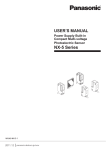
INSTRUCTION MANUAL
MOBILE CONTROLLER
RC-2000
MOBILE CONTROLLER
KENWOOD CORPORATION
© B62-1292-10 (M)
09 08 07 06 05 04 03 02 01
RC-2000
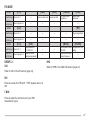
SUPPLIED ACCESSORIES
Accessory
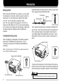
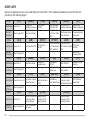
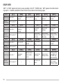
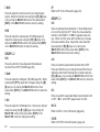
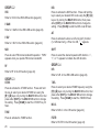
CONVENTIONS FOLLOWED IN THIS MANUAL
The writing conventions described below have been
followed to simplify instructions and avoid unnecessary
repetition.
Part Number
Quantity
–
1
E30-3406-XX
1
Instruction
What to do
E30-3407-XX
1
Press [KEY].
Press and release KEY.
E30-3408-XX
1
Press
[KEY] (1 s).
Press and hold KEY for 1 second or
longer.
E30-3409-XX
1
Press [KEY1],
[KEY2].
Press KEY1 momentarily, release
KEY1, then press KEY2.
J29-0663-XX
J29-0664-XX
Screw set (for RC-2000 bracket) N99-2014-XX
TS-2000(X)/ TS-B2000
A13-0635-XX
Mounting bracket
Spacers (for A13-0635-XX)
J30-0521-XX
Screw set (for A13-0635-XX)
N99-2024-XX
Speaker with cable and plug
T19-0116-XX
Screw set (for T19-0116-XX and
N99-2017-XX
A13-0635-XX)
Line filters:
For microphone (large)
L79-1419-XX
For panel and speaker (small)
L79-1417-XX
Fuse (25 A/ 32 V)
F05-2531-XX
Warranty card:
For the U.S.A. and Canada
B46-0469-XX
For European Countries
B46-0310-XX
Instruction manual
B62-1292-XX
1
1
1
Press [F] (1 s),
[KEY].
Press and hold [F] for 1 second or
longer, then press KEY.
1
Press
[KEY1]+[KEY2].
Press and hold KEY1, then press
KEY2.
2
1
1
Press
[KEY]+
[ ] (POWER).
With transceiver power OFF, press
and hold KEY, then turn ON the
transceiver power by pressing [ ].
{page XX}
Refer to page XX of this manual.
RC-2000 Mobile Controller
DC power cable (7 m/ 23.1 ft)
Microphone extension cable
(5 m/ 16.5 ft)
Speaker extension cable
(5 m/ 16.5 ft)
RC-2000 cable with modular
plugs (5 m/ 16.5 ft)
RC-2000 bracket1
1
2 parts are used.
1
1
2
1
1
1
1
Refer to page XX in the
{TS-2000 page XX} TS-2000(X)/ TS-B2000 instruction
manual.
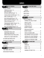
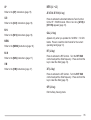
CONTENTS
CHAPTER 1
ABOUT THIS MANUAL
BEFORE YOU BEGIN ............................................... 1
PREPARATION (Pages 2 ~ 6) .............................. 1
QUICK START (Page 7) ....................................... 1
KEYS AND CONTROLS (Pages 8 ~ 12) ............... 1
CYCLING THE KEY GROUPS (Pages 13 ~ 30) ... 1
SATELLITE MODE (Pages 31 ~ 33) ..................... 1
EASY VIEWING MODE (Pages 34 ~ 36) .............. 1
PACKET CLUSTER TUNE (Pages 37 ~ 38) ......... 1
VISUAL SCAN (Pages 39 ~ 40) ............................ 1
PROGRAMMABLE MEMORY (Pages 41 ~ 43) .... 1
SKY COMMAND II+ (Pages 44 ~ 46) .................... 1
QUICK KEY REFERENCE (Pages 47 ~ 51) ......... 1
CHAPTER 2
PREPARATION
INSTALLATION .......................................................... 2
TRANSCEIVER INSTALLATION ........................... 2
FRONT PANEL INSTALLATION ........................... 3
SPEAKER AND MIC CABLE INSTALLATION ....... 4
MODULAR PLUG CABLE CONNECTION ............ 4
DC POWER CABLE INSTALLATION ......................... 5
CHECKING THE CONNECTIONS ............................. 6
QUICK START
CHAPTER 3
PREPARATION ......................................................... 7
OPERATION .............................................................. 7
CHAPTER 4
KEYS AND CONTROLS
FRONT PANEL OVERVIEW ...................................... 8
DISPLAY AND KEY FUNCTIONS ............................ 10
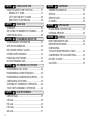
CHAPTER 5
CYCLING THE KEY GROUPS
OVERVIEW ............................................................. 13
DIAGRAM .......................................................... 13
GROUP A KEYS ...................................................... 14
GROUP B KEYS ...................................................... 18
GROUP C KEYS ..................................................... 21
CHAPTER 6
SATELLITE MODE
SATELLITE OPERATION ........................................ 31
ENTERING THE SATELLITE MODE ................ 31
GROUP A–2 KEYS ............................................ 31
BASIC OPERATION .......................................... 32
STORING SATELLITE
MEMORY CHANNELS ...................................... 32
RECALLING A SATELLITE
MEMORY CHANNEL ........................................ 32
SATELLITE CHANNEL NAME .......................... 33
QUICK MEMORY IN SATELLITE MODE .......... 33
CHECKING THE UPLINK FREQUENCY .......... 33
USING XIT/ RIT IN SATELLITE MODE............. 33
CHANGING THE FREQUENCY BAND ............ 33
EASY VIEWING MODE
CHAPTER 7
OVERVIEW ............................................................. 34
OPERATION ...................................................... 34
KEYS (F1 ~ F6) ................................................. 34
KEYS (L1 ~ L3) .................................................. 35
CHANGING THE FONT STYLE ........................ 36
i
CHAPTER 8
PACKET CLUSTER TUNE
PACKET CLUSTER TUNE FUNCTION ................... 37
NORMAL P.C.T. MODE ...................................... 37
LIST FUNCTION IN P.C.T. MODE ....................... 38
NEW PACKET CLUSTER DATA ......................... 38
CHAPTER 9
VISUAL SCAN
OVERVIEW ............................................................. 39
SELECTING THE NUMBER OF CHANNELS .......... 39
USING VISUAL SCAN ............................................. 40
CHAPTER 10
PROGRAMMABLE MEMORY (PM)
PROGRAMMABLE INFORMATION ......................... 41
APPLICATION EXAMPLES ..................................... 42
PM CHANNEL DEFAULT VALUES .......................... 42
STORING IN PM CHANNELS ................................. 43
RECALLING A PM CHANNEL ................................. 43
AUTO PM CHANNEL SAVE .................................... 43
SKY COMMAND II+ (K-TYPE ONLY)
CHAPTER 11
PROGRAMMING CALL SIGNS ............................... 44
PROGRAMMING A TONE FREQUENCY ................ 45
PROGRAMMING COMMUNICATION SPEED ......... 45
CONFIGURING A TNC BAND ................................. 45
STARTING SKY COMMAND II+ OPERATION ......... 46
TO EXIT SKY COMMAND II+ OPERATION ............ 46
CHAPTER 12
QUICK KEY REFERENCE
USB/ LSB mode ...................................................... 47
CW mode ................................................................ 48
FM mode ................................................................. 49
FSK mode ............................................................... 50
AM mode ................................................................. 51
ii
CHAPTER 13
MAINTENANCE
GENERAL INFORMATION ...................................... 52
SERVICE ................................................................. 52
SERVICE NOTE ...................................................... 52
CLEANING .............................................................. 52
CHAPTER 14
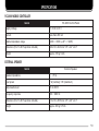
SPECIFICATIONS
RC-2000 MOBILE CONTROLLER ........................... 53
EXTERNAL SPEAKER ............................................ 53
CHAPTER 15
APPENDIX
RESETTING MEMORY DATA ................................. 54
DEMONSTRATION MODE ...................................... 54
CONFIGURING
THE AUTO MODE FREQUENCY TABLE ................ 54
CONCERNING THE TM-D700A/E PANEL ............... 54
NOTICES TO USER ................................................ 55
CAUTIONS .............................................................. 55
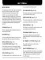
ABOUT THIS MANUAL
BEFORE YOU BEGIN
you are operating in the Satellite mode.
This manual was created to show you how to access the
functions you want to operate, and how to quickly
configure the transceiver, through the use of the
RC-2000. If you are operating the TS-2000(X)/
TS-B2000 transceiver for the first time, we recommend
you read the TS-2000(X)/ TS-B2000 instruction manual
before operating the RC-2000. Since this manual does
not cover the functions in detail, make sure you have the
TS-2000(X)/ TS-B2000 instruction manual handy for
reference.
EASY VIEWING MODE (Pages 34 ~ 36)
PREPARATION (Pages 2 ~ 6)
This chapter describes how to control the functions when
you activate the Visual Scan function.
When you are getting ready to install the brackets and
cables, read this chapter.
QUICK START (Page 7)
If you are operating the RC-2000 for the first time, read
this chapter and follow the instructions for a trial run.
KEYS AND CONTROLS (Page 8 ~ 12)
CYCLING THE KEY GROUPS (Pages 13 ~ 30)
These chapters describe how to access and configure
the various functions available on the RC-2000. Refer to
the page that explains your desired key control.
SATELLITE MODE (Pages 31 ~ 33)
This chapter describes how to control the functions while
This chapter describes how to control the functions while
you are in the Easy Viewing mode.
PACKET CLUSTER TUNE (Pages 37 ~ 38)
This chapter describes how to control the functions when
you activate the Packet Cluster Tune mode.
VISUAL SCAN (Pages 39 ~ 40)
PROGRAMMABLE MEMORY (Pages 41 ~ 43)
This chapter describes how to store and recall the
Programmable Memory function that is available on the
RC-2000.
SKY COMMAND II+ (K-TYPE ONLY) (Pages 44 ~ 46)
This chapter describes how to control the Sky
Command II+ functions.
QUICK KEY REFERENCE (Pages 47 ~ 51)
Alphabetical listing of the key functions in each operating
mode. A Quick look-up table for referring to the page(s)
in this guide as well as the TS-2000(X)/ TS-B2000
instruction manual.
1
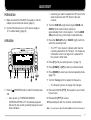
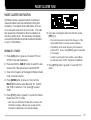
PREPARATION
Install the bracket securely onto the vehicle, using 6 sets
of the supplied screws (N99-2024-XX).
INSTALLATION
When using the RC-2000 in your vehicle, you can install
the transceiver in the trunk, under the seat or under the
dash board. On the transceiver, install the DC cable
(7 m/ 23.1 ft), the microphone extension cable
(5 m/ 16.5 ft), a cable for the speaker (5 m/ 16.5 ft), a
cable to the RC-2000 (5 m/ 16.5 ft), and coaxial cable(s)
to the antenna (not supplied in this package). Make sure
all cable lengths are adequate before installing the
brackets.
TRANSCEIVER INSTALLATION
When installing the metal plates, first attach the plastic
spacers (G11-2698-XX) to the transceiver. This is
necessary to protect the TS-2000(X)/ TS-B2000 from
scratches.
Flat washer
Bracket
Spring washer
Vehicle chassis
Nut
6 mm x 20 mm
Then, prepare the transceiver by loosely screwing in the
rear screws. Hook those screws onto the rear guide rail
of the mounting bracket, then adjust the transceiver to
your desired angle before tightening the screws. Insert
and tighten the front screws to secure the transceiver in
place.
Rear screws
Note: The plastic spacers (G11-2698-XX) are supplied accessories for
the TS-2000(X)/ TS-B2000 transceiver.
Spacers (G11-2698-XX)
4 mm x 10 mm
Front screws
3 mm x 4 mm
The tab faces out
2
The tab faces out
To remove the transceiver from the bracket, first remove
the front screws, then loosen the rear screws slightly and
pull the transceiver forward to unlatch it from the bracket.
Do not install the transceiver so that it is vertically on its side.
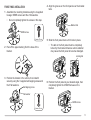
FRONT PANEL INSTALLATION
1 Assemble the mounting brackets using the 2 supplied
hexagon SEMS screws and the 2 flat washers.
•
4 Align the grooves on the front panel over the bracket
tabs.
Do not completely tighten the screws in this step.
Bracket tab
SEMS screw
4 mm x 10 mm
2 Peel off the paper backing from the base of the
bracket.
5 Slide the front panel down until it locks in place.
•
The tab on the front panel must be completely
locked by the bracket otherwise vehicle vibration
may cause the front panel to become dislodged.
Locking tab
3 Position the bracket in the vehicle, then install it
securely using the 3 supplied self-tapping screws and
the 3 flat washers.
Self-tapping screw
6 Position the front panel at your desired angle, then
completely tighten the 2 SEMS screws on the
bracket.
Flat washer
SEMS screw
4 mm x 14 mm
3
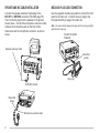
SPEAKER AND MIC CABLE INSTALLATION
MODULAR PLUG CABLE CONNECTION
Connect the speaker extension cable plug to the
EXT.SP1 or EXT.SP2 connector {TS-2000 page 78}.
Then connect a plug from the speaker to the jack as
shown below. Connect the microphone extension cable
between the microphone jack on the front of the
transceiver and the microphone connector, as shown
below.
Use the supplied modular plug cable to connect the front
panel to the main unit. Connect the 4-pin plug to the
front panel and 6-pin plug to the main unit.
Note: It is easy to identify between the plugs, as the 6-pin plug is slightly
wider than the 4-pin plug.
TS-2000/TS-2000X
TS-B2000
Speaker extension cable
Noise filter
(small)
6-pin plug
4-pin plug
Noise filter (small)
Noise filter
(large)
Microphone extention cable
4
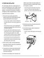
DC POWER CABLE INSTALLATION
The vehicle battery must have a nominal rating of 12 V.
Never connect the transceiver to a 24 V battery. Be sure
to use a 12 V vehicle battery that has sufficient current
capacity. If the current to the transceiver is insufficient,
the display may darken during transmission, or transmit
output power may drop excessively.
attach the power cable to the battery terminals; red
connects to the positive (+) terminal, black connects
to the negative (–) terminal.
• Use the full length of the cable without cutting off any
excess, even if the cable is longer than required. In
particular, never remove the fuse holders from the cable.
Red
1 Route the DC power cable supplied with the
transceiver directly to the vehicle’s battery terminals
using the shortest path from the transceiver.
• If you are using a noise filter, it should be installed with
an insulator to prevent it from touching any metal on the
vehicle.
• We recommend you do not to use the cigarette lighter
socket since some cigarette lighter sockets introduce an
unacceptable voltage drop.
• If the power cable must be routed through a hole in the
vehicle chassis or body, for example in the firewall at the
front of the passenger compartment, use a rubber
grommet to protect the cable from abrasion. Dismantle
the fuse holder to pass the cable through the firewall.
Fuse (25 A)
Black
5 Reconnect any wiring you may have removed from
the negative battery terminal.
6 Connect the DC power cable to the transceiver’s
power supply connector.
• Press the connectors firmly together until the locking tab
clicks.
• The entire length of the cable must be dressed so it is
isolated from heat, moisture, and the engine secondary
(high voltage) ignition system/ cables.
2 After the cable is in place, wind heat-resistant tape
around the fuse holder to protect it from moisture and
tie down the full run of cable.
3 To prevent the risk of short circuits, disconnect other
wiring from the negative (–) battery terminal before
connecting the transceiver.
4 Confirm the correct polarity of the connections, then
5
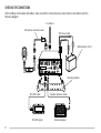
CHECKING THE CONNECTIONS
After installing the brackets and cables, make sure all the connections have been made in accordance with the
following diagram.
To antenna
Microphone extension cable
DC Power cable
Vehicle battery (12 V)
2
ANT 2
AT
ANT
144
1
GND
COM
Microphone
ANT 1.2G
ANT 1
PANEL
EXT. SP2 EXT. SP1
8W
8W
KEY PADDLE
EXT. CONT
ACC2
ANT
430
REMOTE
DC
13.8V
HF
RX ANT
Mounting bracket
RC-2000 cable
RC-2000 panel
6
Speaker extension cable
External speaker
QUICK START
•
PREPARATION
1 Make sure that the RC-2000, the speaker, and the
cables are connected as shown {page 6}.
Assuming you want to operate the HF band on the
main transceiver and VHF band on the subreceiver.
2 Connect the transceiver to a DC power supply or
12 V vehicle battery {page 5}.
2 Turn the SUB SQL (right outer ring) and MAIN and
SUB AF (both center knobs) controls to
approximately the 9 o’clock position. Turn the MAIN
SQL (left outer ring) control fully counterclockwise.
OPERATION
3 Press the MAIN AF (left) or SUB AF (right) control to
select the operating band.
•
MOBILE CONTROLLER
RC-2000
The “PTT” icon moves to indicate which band is
currently selected for the TX band. The frequency
information shown in a large font is selected for
the current control band.
4 Press [F1] until you select group A–1 {page 13}.
5 Press [DOWN] or [UP] to select your desired band.
6 Press [MODE] to select your desired operating mode
{page 15}.
7 Turn the Tuning control to adjust the frequency.
•
1 Press [
ON.
•
] (POWER) briefly to switch the transceiver
Upon power up, “KENWOOD MOBILE
CONTROLLER HELLO!!” momentarily appears,
followed by the current operating frequencies and
other indicators.
The frequency shown in a large font changes.
8 Press and hold Mic [PTT], then speak in your normal
tone of voice.
9 Release Mic [PTT] to receive.
10 Repeat steps 8 and 9 to continue communication.
Note: You may have to adjust the AF and SQL controls further in step 6.
7
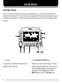
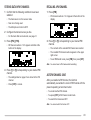
KEYS AND CONTROLS
FRONT PANEL OVERVIEW
There are 12 keys on the front panel. These keys are denoted as follows: L1 ~ L3 are the 3 keys to the left of the
display (from top to bottom); F1 ~ F6 are the 6 keys below the display (from left to right); the top most key to the right of
the display is the Power switch; R1 ~ R2 are the two keys below the Power switch, to the right of the display (from top
to bottom).
MOBILE CONTROLLER
RC-2000
q L1 ~ L3 key
w Tuning / MULTI/CH / RIT/SUB control
Press to activate or select the function shown on the
display to the right of each key.
Normally, it is used to adjust the frequency. Press this
control to change the control mode. The current tuning
control mode status appears on the top right of the
display where “TUN” is Tuning control, “MLTI” is
MULTI/ CH control, and “RIT” is RIT/ SUB control.
8
e F1 key
o
Press momentarily to cycle within each group (for
example, A–1 a A–2 a A–3 a A–4 a A–1). Press
and hold to cycle among groups (Group A a Group B a
Group C a Group A) {page 13}. The selected group
and corresponding number appear on the display above
this key.
Press to switch the transceiver ON or OFF {TS-2000
page 8}.
(POWER) switch
!0 R1 ~ R2 key
Press to activate or select the function shown on the
display to the left of each key.
r F2 ~ F6 key
Press to activate or select the function shown on the
display above each key {page 13 ~ 30}.
t MAIN AF control
Functions the same as the MAIN AF control on the
transceiver. If you press this control, it functions the
same as [MAIN] on the transceiver {TS-2000 page 12}.
y MAIN SQL control
Functions the same as the MAIN SQL control on the
transceiver {TS-2000 page 12} .
u SUB AF control
Functions the same as the SUB AF control on the
transceiver. If you press this control, it functions the
same as [SUB] on the transceiver {TS-2000 page 12}.
i SUB SQL control
Functions the same as the SUB SQL control on the
transceiver {TS-2000 page 12}.
9
!0 The assigned function of [R2] appears. Normally,
“RIT” appears. Press [R2] to switch RIT ON or OFF.
Press and hold the key to clear the RIT offset
frequency.
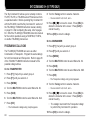
DISPLAY AND KEY FUNCTIONS
#9 #8 #7 #6 #5 #4
#3
#2
#1
#0 @9 @8 @7 @6
!1
!1 The assigned function of [R1] appears. Normally,
“PM” appears. Press to enter Programmable Memory
function {page 41}.
!0
!2 The main transceiver operating frequency display.
q
w
e
r !2 !3 t !4 !5 y !6 !7 !8 u !9 @0 i @1 o @2 @3 @4 @5
q “AT” appears when you operate HF ~ 50 MHz band.
Press [L1] to activate the automatic antenna tuner.
While it is in-line, “AT IN” or “AT R IN” appears (when
Menu No. 27 is “ON”). “CALL” appears when you
operate 144 MHz ~ 1.2 GHz bands. Press [L1] to
recall the CALL channel for the band or press and
hold [L1] to store the new CALL channel data.
w While “Q.IN” appears, press [L2] to store the current
frequency and other data to the Quick Memory.
e “EASY” appears when you operate the normal
VFO/ Memory Recall mode. Press [L3] to enter Easy
Viewing mode {page 34}.
r Displays the current key group and its suffix number.
Press [F1] to move to next suffix number or press
and hold [F1] to move to next group {page 13}.
t~o
The available function name appears. Press [F2] ~
[F6] or press and hold the key to activate the function
{pages 13 ~ 30}.
10
!3 When the main transceiver receives a signal or the
main transceiver’s squelch is open, “BSY” appears.
When you transmit on the main transceiver, “TX”
appears.
!4 The memory name appears when you recall the
memory channel. “CALL” appears when you recall
the CALL channel. “SCAN–P1” (slowest scan
speed) ~ “SCAN–P9” (fastest scan speed) appears
while in Scan mode.
!5 “S” appears when the main transceiver is in receive
mode. “PWR” (output power), “SWR” (SWR ratio), or
“ALC” (Automatic Level Control) appears when you
select the meter function.
!6 The memory channel number appears (3 digits) when
you recall the Memory channel. The memory group
number “0–” ~ “9–” also appears. When the channel
is locked out, “— — —” appears above the memory
channel number. “Q01” ~ “Q09” appears when you
recall a Quick Memory channel. The Satellite
memory channel number “0” ~ “9” appears in the
Satellite mode. If no data is stored “s” appears
along with the memory channel number.
!7 Works as an S-meter in the receive mode. Works as
the meter you selected while transmitting.
@9 “DSP” appears when one of the DSP functions is
activated.
!8 “ ” appears when the internal TNC is assigned to the
main transceiver.
#0 “AGC” appears when the AGC function is ON. “R”
(Reverse function), “[R]” (Automatic Simplex Check),
or the Repeater shift direction (“–”, “+”, or “=”)
appears.
!9 The Hz digits of the main transceiver operating
frequency appears.
@0 Appears when the frequency point of Program Scan
Partially Slowed is selected on the main transceiver.
@1 When the sub-receiver is switched ON, it shows the
operating frequency for the sub-receiver. However, if
you are controlling the main transceiver functions,
such as RIT, XIT or SPLIT, it displays the frequency
information for these functions.
Note: “=” appears only for E-types.
#1 “ATT” appears when the attenuator function is ON.
“PRE” appears when the preamplifier function is ON.
“P/A” appears when both functions are ON.
#2 “RtEQ” appears when the RX Equalizer function of
the main transceiver is ON. “EQsT” appears when
the TX equalizer function is ON.
@2 Serves as an S-meter for the sub-receiver. It also
displays the relative output power when the sub-band
is selected for transmission.
#3 “EXT” appears while the HF RX ANT connector is
enabled to receive HF band signals.
@3 Appears when the MHz Up/ Down mode is selected.
#5 “A” appears when Auto mode selection is activated.
@4 Appears when the Fine tuning function is selected.
#6 The current operating mode for the main transceiver
appears.
@5 “PKT” appears when the internal TNC is operating in
Packet mode.
@6 “tM” or “Ms” appears while a simplex memory
channel is selected. “tMs” appears while a split
frequency memory channel is selected.
@7 “tB” or “Bs” appears while VFO B is selected. “B”
appears while Menu B is being accessed.
#4 “NB” appears when the Noise Blanker function is ON.
#7 “PROC” appears when the Speech Processor
function is ON.
#8 “PTT” appears when the main transceiver is selected
for the transmission band. “Ctrl” appears when the
main transceiver is selected for the Control band.
#9 “VOX” appears when the VOX function is ON.
@8 “tA” or “As” appears while VFO A is selected. “A”
appears while Menu A is being accessed.
11
$0
$1
$2
$3 $4 $5 $6 $7 $8 $9
%0
%1
%2
%3
%4
%8
%7
%6
%5
$0 “TRC” appears when the Trace function is ON in the
Satellite mode. “TRCR” appears when the Reverse
Trace function is ON in the Satellite mode.
Check), or the Repeater shift direction (“–”, “+”, or “=”)
appears.
Note: “=” appears only for E-types.
$9 “N.R.1” appears when the Noise Reduction 1 function
is ON for the sub-receiver.
%0 “TUN” (Tuning control), “MLTI” (MULTI/ CH control),
“RIT” (RIT/ SUB control), or “SPED” (Scanning speed
control) appears, indicating which control mode is
currently assigned to the Tuning control.
%1 Appears when the Programmable Memory function is
ON. “PM1” ~ “PM5” appear to indicate which
Programmable Memory channel is selected.
$1 “SATL” appears while operating in Satellite mode.
%2 “PC” appears when the TS-2000(X)/ TS-B2000 is
controlled by an external PC.
$2 “PTT” appears when the sub-band is selected for the
transmission band. “Ctrl” appears when the subband is selected for the Control band.
%3 “ ” appears when the internal TNC is assigned to the
sub-receiver.
$3 The current operating mode for the sub-receiver
(sub-band) appears.
$4 “RIT” appears while the RIT function is ON. “XIT”
appears while the XIT function is ON.
$5 “SPL” appears while SPLIT operation is enabled.
$6 “DCS” (DCS function), “CT” (CTCSS function), or “T”
(Tone function) appears when one of the FM mode
selective calls is activated for the sub-receiver.
$7 “ATT” appears when the attenuator function is ON.
“PRE” appears when the preamplifier function is ON.
“P/A” appears when both functions are ON.
$8 “R” (Reverse function), “[R]” (Automatic Simplex
12
%4 The sub-receiver operating frequency display.
%5 The memory channel number appears (3 digits) when
you recall the Memory channel on the sub-receiver.
(Same as !6.)
%6 “S” appears when the sub-receiver’s squelch opens.
“PWR” appears to display the relative output power
level when you transmit on the sub-band.
%7 When a memory channel is recalled to the subreceiver, the memory name appears. (Same as !4.)
%8 When the sub-receiver receives a signal or the subreceiver’s squelch is open, “BSY” appears. When
you transmit on the sub-band, “TX” appears.
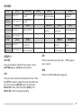
CYCLING THE KEY GROUPS
OVERVIEW
The TS-2000(X)/ TS-B2000 transceiver has many
function controls. However, the RC-2000 mobile
controller has only 12 keys and 5 controls. In order to
access all the available functions of the transceiver from
the RC-2000 mobile controller, the functions are divided
into 3 groups: A, B, and C. Group A is a primary
function group with most of the commonly used keys.
Group B is a secondary function group. Group C is a
special group whose functions change, depending on
the current operating mode.
Within each group, there are several sub-groups, each
identified by their suffix numbers. Momentarily press
[F1] to cycle through each sub-group within your
selected group (A, B, or C). The suffix numbers change
to reflect the currently selected sub-group. To change
the main group (A, B, or C), press and hold [F1].
As you change the group and sub-group, the available
functions for [F2] ~ [F6] change. Press one of [F2] ~
[F6] to activate the function which appears on the
display above each key.
The following diagram illustrates how to access each
group and sub-group.
For further information on each function, refer to the
TS-2000(X)/ TS-B2000 instruction manual. A Quick
look-up table of each operating mode is available,
starting on page 47.
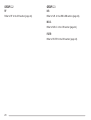
DIAGRAM
GROUP A
[F1]
(1 s)
A–1
[F1]
(1 s)
B–1
[F1]
A–2
C–2
B–3
A–4
[F1]
[F1]
C–3
[F1]
[F1]
[F1]
[F1]
(1 s)
[F1]
[F1]
[F1]
A–3
GROUP C
C–1
B–2
B–4
[F1]
To access your desired function, first select the
appropriate group by pressing and holding [F1]. Next,
cycle within the group to the appropriate sub-group by
continuously pressing [F1]. The selected group and
corresponding number appears on the display above the
[F1] key.
GROUP B
(C–4)
[F1]
[F1]
(A–5)
[F1]
Press [F1]
• A–5 appears only when recalling
Memory Channels 290~299.
Press [F1] (1 s) • C–4 appears only in FM mode.
13
GROUP A KEYS
Group A–5 appears only when you recall Memory Channel 290 ~ 299. Detailed explanations of each function are
provided on the following pages:
Action
[A–1]
Press the key: Move to A–2
Press and
hold the key:
Action
Move to group B–1
[A–2]
Press the key: Move to A–3
Press and
hold the key:
Action
Move to group B–1
[A–3]
Press the key: Move to A–4
Press and
hold the key:
Action
Move to group B–1
[A–4]
Press the key: Move to A–5 or A–1
Press and
hold the key:
Action
Move to group B–1
[A–5]
Press the key: Move to A–1
Press and
hold the key:
14
Move to group B–1
[MODE]
[FINE]
Change the
FINE function
operating mode pair ON/ OFF
Toggle the mode
within the selected
—
pair
[A/B]
Select another VFO
—
[MENU]
Enter Menu mode
–
[CLR]
Exit, abort, or reset
various functions
[SPLIT]
SPLIT function
ON/ OFF
—
[STEP]
Change the
frequency step
—
[M>V]
[1MHz]
1 MHz Up/ Down
control ON/ OFF
Change the step
size for the 1 MHz
control
[TF SET]
Check and change
the TX frequency in
SPLIT operation
—
[NB]
—
[SET]
[OPEN]
Add the current freq. Display the start
to the Prog. Scan
frequency of the
Partially Slowed
memory channel
Clear all the above
—
freq. points
[UP]
Move up one
amateur radio band
Continuously move
down the band
Continuously move
up the band
[A=B]
[MG SEL]
—
[XIT]
Copy the current
XIT function
VFO data to another
ON/ OFF
VFO
Clear the XIT
—
frequency offset
[AGC]
Noise Blanker
AGC ON/ OFF
ON/ OFF
Configure the Noise Configure the AGC
Blanker level
time constant
Transfer data from a
Enter Memory
Memory channel to
Group Select mode
a VFO
—
[DOWN]
Move down one
amateur radio band
[M.IN]
[PF]
Activate PF (Prog.
Function)
—
[V/M]
Write data into
VFO or Memory
memory or enter
Recall mode
Memory Scroll mode
—
—
[CLOSE]
—
—
Display the end
frequency of the
memory channel
—
—
—
GROUP A-1
GROUP A–2
MODE
A/B
Press to change the operating mode pair. There are 3
pairs: USB/ LSB, FM/ AM, and CW/ FSK. Press and
hold to toggle the mode within each pair: USB
LSB,
FM
AM, or CW
FSK.
Press to alternate between VFO A and VFO B on the
main transceiver.
FINE
Press to activate SPLIT operation on the main
transceiver.
Press to toggle the FINE tuning function ON or OFF. “F”
appears on the display when this function is ON.
TF SET
1MHz
Press to toggle the 1MHz Up/ Down function ON or OFF.
“M” appears on the display when this function is ON.
Press and hold to change the 1MHz Up/ Down frequency
step size. Press the [c]/ [d] keys or turn the
MULTI/ CH control to change the frequency step size,
then press either [EXIT] or the MULTI/ CH control to
accept the new setting.
DOWN
Press to move down the amateur radio band one step.
Press and hold to continuously cycle down through the
amateur radio bands.
UP
SPLIT
When SPLIT operation is activated, press and hold this
key, then turn the Tuning control to adjust the TX
frequency. Press the Tuning control to toggle between
the Tuning control and MULTI/ CH control mode. “TUN”
or “MLTI” appears on the display to indicate the selected
control mode.
A=B
Press to copy the data of the currently selected VFO to
another VFO.
XIT
Press to switch the Transmit Incremental Tuning function
ON or OFF. When it is ON, “XIT” appears on the display,
along with the offset frequency. Press and hold to clear
the XIT offset frequency.
Press to move up the amateur radio band one step.
Press and hold to continuously cycle up through the
amateur radio bands.
15
GROUP A-3
MENU
Press to enter the Menu mode. Menu mode is used to
activate and configure the various functions of the
TS-2000(X)/ TS-B2000 {TS-2000 page 21}. Press
[ADD] to add the current Menu No. to the Quick Menu.
“ ” appears on the display when the Menu No. is added
to the Quick Menu. Press [MNU SEL] to activate the
Quick Menu function.
STEP
Press to change the frequency step size used for the
MULTI/ CH control {TS-2000 page 37}. Select the
desired step size using the [c]/ [d] keys or by turning
MULTI/ CH control, then press either [EXIT] or the
MULTI/ CH control to accept the new setting.
NB
Press to switch the Noise Blanker function ON or OFF.
When it is ON, “NB” appears on the display. Press and
hold to change the Noise Blanker Level. Select the
desired level using the [c]/ [d] keys or by turning the
MULTI/ CH control, then press either [EXIT] or the
MULTI/ CH control to accept the new setting.
AGC
Press to switch the AGC function ON or OFF. When it is
ON, “AGC” appears on the display. Press and hold to
change the AGC Level {TS-2000 page 38}. Select the
desired time constant using the [b]/ [a] keys or by
turning the MULTI/ CH control, then press either [EXIT]
16
or the MULTI/ CH control to accept the new setting.
PF
Press to activate the PF (Programmable Function) key
assignment. The default assignment is VOICE1
{TS-2000 page 77}.
GROUP A–4
CLR
Press to exit from, abort, or reset various functions. Also
used for erasing memory channels {TS-2000 page 62} or
locking memory channels out of the scan list {TS-2000
page 62}.
M>V
Press to transfer data from a memory channel to a VFO
{TS-2000 page 61}.
MG SEL
Press to enter Memory Group Select mode {TS-2000
page 64}. The selected group numbers are highlighted.
You can select your desired group numbers using the
[b]/ [a] keys, or by turning or pressing the MULTI/ CH
control, then press [SEL] to toggle the selection. You
can also press [ALL] to unselect all the group numbers.
Press [OK] to save the setting or [CLR] to cancel the
selection.
M.IN
GROUP A–5
Press to enter the Memory Scroll mode {TS-2000
page 60}. “MSR” appears on the display. Turn the
MULTI/ CH control to select your desired memory
channel number. Press [M.IN] to write the data to
memory. You can also press [MN.IN] to enter and select
the Memory Name and Memory Group. Select your
desired character using the MULTI/ CH control, or the
[b]/ [a] and [DEL] keys. Press [OK] to store the
Memory Name. Press [G-SEL] to enter the Memory
Group selection. Select a desired Memory Group using
the MULTI/ CH control or [b]/ [a] keys, then press
[SEL]. Press [OK] to store the new Memory Group
selection.
A–5 functions appear only when recalling Memory
Channels 290 ~ 299 {TS-2000 page 62}.
V/M
Press to select either VFO or Memory Recall mode
{TS-2000 page 59}. In Memory Recall mode, “tM” or
“Ms” appears on the display. Turn the MULTI/ CH
control to select your desired memory channel.
SET
Turn the Tuning control and press [SET] to set the
frequency point of Program Scan Partially Slowed on the
main transceiver {TS-2000 page 67}. The “ ” icon
appears on the display when you tune to the marked
frequency. Press and hold the key to clear all the
frequency points that you have configured.
OPEN
Press to confirm the start frequency when you recall a
memory channel from 290 ~ 299 {TS-2000 page 62}.
CLOSE
Press to confirm the end frequency when you recall a
memory channel from 290 ~ 299 {TS-2000 page 62}.
17
GROUP B KEYS
“ANT1” or “ANT2” appears only when you are operating on the HF ~ 50 MHz band. “ANT” appears for all other bands
in group B–1. Detailed explanations of each function are provided on the following pages:
Action
[B–1]
Press the key: Move to B–2
Press and
hold the key:
Action
Move to group C–1
[B–2]
Press the key: Move to B–3
Press and
hold the key:
Action
Move to group C–1
[B–3]
Press the key: Move to B–4
Press and
hold the key:
Action
Move to group C–1
[B–4]
Press the key: Move to B–1
Press and
hold the key:
18
Move to group C–1
[PRE]
Pre-amplifier
ON/ OFF
—
[ATT]
—
[REC]
Stand-by for
recording a
message
—
[SCAN]
Scan ON/ OFF
[ANT1]
Select another
Attenuator ON/ OFF
antenna
[P.C.T.]
—
—
—
[CH1]
[CH2]
[CH3]
—
Play the CH1
message
—
Record a voice
Record a voice
Record a voice
message on CH1 in message on CH2 in message on CH3 in
REC mode
REC mode
REC mode
[AUTO]
Auto-mode function
ON/ OFF
Play the CH2
message
[SG SEL]
Select the Scan
Group
[VISUAL]
—
—
—
—
—
[DUAL]
[CTRL]
[LOCK]
[Q.M]
—
Move the Control
band to another
receiver
—
Activate the Key
lock function
Exit the Key lock
function
Play the CH3
message
Visual Scan
ON/ OFF
—
Sub-receiver
ON/ OFF
[SATL]
Packet Cluster Tune Satellite Mode
ON/ OFF
ON/ OFF
Recall a Quick
Memory channel
—
[METER]
Change the meter
mode (SWR, ALC,
and COMP only)
while transmitting
Toggle the meter
mode: PWR or
SWR/ ALC/ COMP
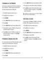
GROUP B–1
GROUP B–2
PRE
REC
Press to switch the receiver preamplifier ON or OFF
{TS-2000 page 57}. “PRE” appears on the display when
this function is ON. “P/A” appears on the display when
both “PRE” and “ATT” are ON.
Press to enter stand-by mode for message recording
{TS-2000 pages 43, 89}. To start recording a message,
press [CH1], [CH2], or [CH3].
CH1
ATT
Press to switch the receiver attenuator ON or OFF.
“ATT” appears on the display when this function is ON.
“P/A” appears on the display when both “PRE” and “ATT”
are ON.
Press to play back the message which has been
recorded in channel 1. When [REC] is pressed and the
transceiver is standing by for recording, press this key to
start recording in CH1.
CH2
ANT1/ ANT2/ ANT
When operating on the HF ~ 50 MHz band, “ANT1” or
“ANT2” appears. “ANT” appears when operating on the
144 MHz ~ 1.2 GHz bands. Press to select another
antenna when operating on the HF ~ 50 MHz band.
Press to play back the message which has been
recorded in channel 2. When [REC] is pressed and the
transceiver is standing by for recording, press this key to
start recording in CH2.
CH3
P.C.T.
Press to switch the P.C.T. (Packet Cluster Tune) function
ON or OFF {page 37, TS-2000 page 53}.
Press to play back the message which has been
recorded in channel 3. When [REC] is pressed and the
transceiver is standing by for recording, press this key to
start recording in CH3.
SATL
Press to switch the Satellite mode ON or OFF {page 31,
TS-2000 page 53}.
19
GROUP B–3
GROUP B–4
SCAN
DUAL
Press to start or stop various Scan functions.
Press to switch the sub-receiver ON or OFF.
AUTO
CTRL
Press to switch the Auto mode selection function ON or
OFF. When it is active, “A” appears on the display.
Press to move the Control band to another receiver. The
frequency display of the Control band appears in a large
font. If the same band is selected for the TX band and
Control band, only “PTT” appears on the display.
SG SEL
Press to enter the Scan Group select mode. Select your
desired memory group numbers using the [b]/ [a] key,
or by turning or pressing the MULTI/ CH control, then
press [SEL] to toggle the selection. The selected group
numbers are highlighted. You can also press [ALL] to
deselect all the group numbers. Press [OK] to save the
setting or [CLR] to cancel the selection.
LOCK
VISUAL
Press to recall the Quick Memory channel. “Qnn”
appears, indicating which Quick Memory channel is
recalled (where “nn” = 00 ~ 09). Turn the MULTI/ CH
control to scroll through the Quick Memory channels.
Press to activate the Visual Scan function {page 39,
TS-2000 page 70}.
Press to lock all the keys and controls of the RC-2000.
Press and hold to unlock the keys and controls of the
RC-2000.
Q.M
METER
Press to change the meter mode between SWR, ALC,
and COMP. Press and hold to toggle the meter mode
between PWR and SWR/ ALC/ COMP.
20
GROUP C KEYS
The available group C keys change, depending on the current operating mode. Detailed explanations of each function
are provided on the following pages:
USB/ LSB MODE
Action
[C–1]
Press the key: Move to C–2
Press and
hold the key:
Action
Move to group A–1
[C–2]
Press the key: Move to C–3
Press and
hold the key:
Action
Move to group A–1
[C–3]
Press the key: Move to C–1
Press and
hold the key:
Move to group A–1
[PROC]
[MIC]
Speech Processor
ON/ OFF
Speech Processor
input level
adjustment
[VOX]
VOX ON/ OFF
—
—
[N.R.]
—
[V GAIN]
—
[V DLY]
[PWR]
Output power
adjustment
—
[RF]
VOX gain
adjustment
VOX delay
adjustment
—
RF gain adjustment
—
—
—
—
[M.B.C.]
[FILTER]
—
Noise Reduction 1
or 2 ON/ OFF
Adjust the Noise
Reduction parameter
[T-MON]
TX Monitor level
MIC gain adjustment
adjustment
[A.N.]
Auto Notch
ON/ OFF
Auto Notch level
adjustment
[B.C.]
Beat Cancel
ON/ OFF
—
Manual Beat Cancel Configure DSP filter
ON/ OFF
setting
Adjust Manual Beat
—
Cancel frequency
GROUP C–1
MIC
PROC
Press to enter the Mic Gain adjustment mode. While
pressing Mic [PTT], speak in your normal tone and level
of voice. Adjust the microphone gain using the [c]/ [d]
keys or by turning the MULTI/ CH control, then press
either [EXIT] or the MULTI/ CH control to store the
setting. While the Speech Processor function is ON, it
works as the Speech Processor output level adjustment
control.
Press to switch the Speech Processor function ON or
OFF. “PROC” appears on the display when it is ON.
Press and hold to configure the Speech Processor
compression level. While pressing Mic [PTT], speak in
your normal tone and level of voice. Adjust the input
level using the [c]/ [d] keys or by turning the
MULTI/ CH control, then press either [EXIT] or the
MULTI/ CH control to accept the new setting.
21
T-MON
Press to adjust the monitor level of your transmission
signal. Adjust the monitor level using the [c]/ [d] keys
or by turning the MULTI/ CH control, then press either
[EXIT] or the MULTI/ CH control to store the setting.
PWR
Press to adjust the output power {TS-2000 page 20}.
Adjust the output power using the [c]/ [d] keys or by
turning the MULTI/ CH control, then press either [EXIT]
or the MULTI/ CH control to store the setting.
GROUP C–2
VOX
Press to switch the Voice-Operated Transmission
function ON or OFF {TS-2000 page 39}.
V GAIN
Press to adjust the VOX gain {TS-2000 page 39}. While
pressing Mic [PTT], adjust the VOX gain using the [c]/
[d] keys or by turning the MULTI/ CH control, then
press either [EXIT] or the MULTI/ CH control to store the
setting.
V DLY
Press to adjust the VOX delay time. Select your desired
delay time using the [c]/ [d] keys or by turning the
MULTI/ CH control, then press either [EXIT] or the
MULTI/ CH control to change the setting.
RF
Refer to RF in the CW section {page 24}.
GROUP C–3
N.R.
Press to activate Noise Reduction 1, Noise Reduction 2,
or to turn the function OFF. When the noise reduction
function is ON, “N.R.1” or “N.R.2” appears above the
key. When it is ON, press and hold the key to change
the noise reduction level. Adjust the noise reduction
level using the [c]/ [d] keys or by turning the
MULTI/ CH control, then press either [EXIT] or the
MULTI/ CH control to store the setting.
A.N.
Press to switch the Auto Notch function ON or OFF.
Press and hold the key to change the Auto Notch level.
Adjust the Auto Notch tracking time constant using the
[c]/ [d] keys or by turning the MULTI/ CH control, then
press either [EXIT] or the MULTI/ CH control to store the
setting.
B.C.
Press to switch the automatic Beat Cancel function ON
or OFF. “B.C.” and “DSP” appear when it is ON.
M.B.C.
Refer to M.B.C. in the CW section {page 24}.
FILTER
Refer to FILTER in the CW section {page 24}.
22
CW MODE
Action
[C–1]
Press the key: Move to C–2
Press and
hold the key:
Action
Move to group A–1
[C–2]
Press the key: Move to C–3
Press and
hold the key:
Action
Move to group A–1
[C–3]
Press the key: Move to C–1
Press and
hold the key:
Move to group A–1
[CW TUN]
CW Tune function
ON/ OFF
CW Tune function
ON/ OFF
[CAR]
[REV]
Reverse the sideAdjust a carrier level
tone pitch frequency
—
—
[VOX]
Break-in ON/ OFF
—
[BK DLY]
—
Adjust the Break-in
delay time
—
—
[N.R.]
Noise Reduction 1
or 2 ON/ OFF
Adjust the Noise
Reductoin parameter
—
—
—
—
[PWR]
—
Output power
adjustment
—
—
[KEY]
[RF]
Adjust the electric
keyer speed
RF gain adjustment
—
—
[M.B.C.]
[FILTER]
Manual Beat Cancel Configure DSP filter
ON/ OFF
setting
Adjust Manual Beat
—
Cancel frequency
GROUP C–1
REV
CW TUNE
Press to reverse the side-tone pitch. “CWR” appears
when it is ON.
Press to activate the CW Auto Tune function. Press
[CW TUN] again or [CLR] to exit the function.
CAR
PWR
Refer to the USB/ LSB section {page 22}.
Press to enter the carrier level adjustment mode. Press
Mic [PTT] to transmit. Adjust the carrier level within the
ALC zone using the [c]/ [d] keys or by turning the
MULTI/ CH control, then press either [EXIT] or the
MULTI/ CH control to change the setting.
23
GROUP C–2
GROUP C–3
VOX
N.R.
Press to switch the CW break-in function ON or OFF.
Refer to N.R. in the USB/ LSB section {page 22}.
BK DLY
M.B.C.
Press to adjust the CW break-in delay time {TS-2000
page 42}. Select your desired break-in delay time using
the [c]/ [d] keys or by turning the MULTI/ CH control,
then press either [EXIT] or the MULTI/ CH control to
change the setting. The values range from FBK (full
break-in) to 100 which is the slowest delay time.
Press to switch the Manual Beat Cancel function ON or
OFF. Press and hold the key to enter the manual beat
cancel frequency adjustment mode. Adjust the beat
cancel frequency using the [c]/ [d] keys or by turning
the MULTI/ CH control, then press either [EXIT] or the
MULTI/ CH control to store the setting.
KEY
FILTER
Press to adjust the keying speed of the electric keyer.
Select your desired keying speed using the [c]/ [d]
keys or by turning the MULTI/ CH control, then press
either [EXIT] or MULTI/ CH control to change the setting.
The adjustable keying speed is between 10 (WPM) and
60 (WPM).
USB/ LSB/ FM/ AM mode:
Press to adjust the low cut-off or high cut-off frequency
of the DSP. Press [HI] or [LOW] to select the high or
c]/ [d
d] or turn the MULTI/ CH
low cut-off, then press [c
control to select the desired cut-off frequency. Press
[EXIT] or MULTI/ CH control to accept the new setting.
RF
Press to adjust the Radio Frequency (RF) gain for the
main transceiver. Select your desired RF gain value
using the [c]/ [d] keys or by turning the MULTI/ CH
control, then press either [EXIT] or the MULTI/ CH
control to change the setting. The minimum RF gain
value is 0 and the maximum value is 255.
24
CW/ FSK mode:
Press to adjust the DSP filter width or shift frequency.
Press [SFT] to adjust the shift frequency, then press
c]/ [d
d ] or turn the MULTI/ CH control to select the
[c
desired shift frequency. Press [EXIT] to accept the new
setting. Press [WID] to adjust the filter width, then press
c]/ [d
d ] or turn the MULTI/ CH control to select the
[c
desired shift frequency. Press [EXIT] or MULTI/ CH
control to accept the new setting.
FM MODE
Action
[C–1]
Press the key Move to C–2
Press and
hold the key
Action
Move to group A–1
[C–2]
Press the key Move to C–3
Press and
hold the key
Action
Move to group A–1
[C–3]
Press the key Move to C–4
Press and
hold the key
Action
Move to group A–1
[C–4]
Press the key Move to C–1
Press and
hold the key
Move to group A–1
[PROC]
Speech Processor
ON/ OFF
Speech Processor
input level
adjustment
[ASC]
[REV]
Automatic Simplex
Check ON/ OFF
Shift reverse
ON/ OFF
—
[VOX]
—
[V GAIN]
[V DLY]
[T-MON]
TX Monitor level
adjustment
—
—
[NAR]
[RF]
VOX gain
adjustment
VOX delay
adjustment
—
—
—
—
[CTCSS]
[TONE]
[DCS]
[ALT]
VOX ON/ OFF
CTCSS ON/ OFF
TONE ON/ OFF
DCS ON/ OFF
Select CTCSS tone
Transmit 1750 Hz
tone
Select DCS code
[N.R.]
[T.SEL]
Narrow bandwidth
ON/ OFF
ALT ON/ OFF
—
[M.B.C.]
Noise Reduction1
Select a sub-tone
ON/ OFF
frequency
Configure the Noise
—
Reduction parameter
—
—
[PWR]
Output power
adjustment
RF gain adjustment
—
[SHIFT]
Select the
SHIFTdirection
Adjust the offset
frequency
[FILTER]
Manual Beat Cancel Configure DSP filter
ON/ OFF
settings
Adjust Manual Beat
—
Cancel frequency
GROUP C–1
REV
PROC
Refer to PROC in the USB/ LSB section {page 21}.
Press to swap the TX and RX frequency when the
SHIFT function is ON.
ASC
T-MON
Press to switch the Automatic Simplex function ON/ OFF.
When it is ON, “[R]” appears.
Refer to T-MON in the USB/ LSB section {page 22}.
PWR
Refer to PWR in the USB/ LSB section {page 22} .
25
GROUP C–2
DCS
VOX
Press to activate the DCS function. Press and hold the
key to select your desired DCS code using the [c]/ [d]
keys or by turning the MULTI/ CH control, then press
either [EXIT] or the MULTI/ CH control to change the
setting. Press [SCAN] to start the DCS code ID Scan.
Refer to VOX in the USB/ LSB section {page 22} .
V GAIN
Refer to V GAIN in the USB/ LSB section {page 22}.
ALT
V DLY
Refer to V DLY in the USB/ LSB section {page 22}.
Press to activate the Auto Lock Tuning (ALT) function
(1.2 GHz band only). When it is ON, “ ” appears.
NAR
SHIFT
Press to select FM narrow bandwidth operation. “FMN”
appears when you operate FM narrow bandwidth.
Press to select the desired repeater shift direction. “–”,
“+”, or “=” appears to indicate the shift direction.
RF
GROUP C–4
Refer to RF in the CW section {page 24}.
N.R.
Refer to N.R. in the USB/ LSB section {page 22}.
GROUP C–3
CTCSS
T.SEL
Press to activate the CTCSS function. Press and hold
the key to select your desired CTCSS tone using the
[c]/ [d] keys or by turning the MULTI/ CH control, then
press either [EXIT] or the MULTI/ CH control to change
the setting. Press [SCAN] to start the CTCSS Freq. ID
Scan.
Press to select your desired TONE frequency using the
[c]/ [d] keys or by turning the MULTI/ CH control, then
press either [EXIT] or the MULTI/ CH control to change
the setting. Press [SCAN] to start the TONE ID Scan.
TONE
Press to activate the TONE function.
M.B.C.
Refer to M.B.C. in the CW section {page 24}.
FILTER
Refer to FILTER in the CW section {page 24}.
26
FSK MODE
Action
[C–1]
[CAR]
Press the key: Move to C–2
—
Press and
hold the key:
—
Action
Move to group A–1
[REV]
Adjust a carrier level Reverse the shift
—
—
[T-MON]
TX Monitor level
adjustment
—
[C–2]
[PWR]
Output power
adjustment
—
[RF]
Press the key: Move to C–3
—
—
—
—
RF gain adjustment
Press and
hold the key:
—
—
—
—
—
[M.B.C.]
[FILTER]
Action
Move to group A–1
[C–3]
Press the key: Move to C–1
Press and
hold the key:
Move to group A–1
[N.R.]
Noise Reduction 1
or 2 ON/ OFF
Adjust the Noise
Reduction parameter
—
—
—
—
Manual Beat Cancel Configure DSP filter
ON/ OFF
setting
Adjust Manual Beat
—
Cancel frequency
GROUP C–1
PWR
CAR
Refer to PWR in the USB/ LSB section {page 22} .
Refer to CAR in the CW section {page 23}.
REV
Press to reverse the FSK shift. “FSR” appears when it is
ON.
T-MON
Press to adjust the monitor level of your FSK
transmission signal.
27
GROUP C–2
GROUP C–3
RF
N.R.
Refer to RF in the CW section {page 24}.
Refer to N.R. in the USB/ LSB section {page 22}.
M.B.C.
Refer to M.B.C. in the CW section {page 24}.
FILTER
Refer to FILTER in the CW section {page 24}.
28
AM MODE
Action
[C–1]
Press the key Move to C–2
Press and
hold the key
Action
Move to group A–1
[C–2]
Press the key Move to C–3
Press and
hold the key
Action
Move to group A–1
[C–3]
Press the key Move to C–1
Press and
hold the key
Move to group A–1
[PROC]
Speech Processor
ON/ OFF
Speech Processor
input level
adjustment
[CAR]
[T-MON]
TX Monitor level
Adjust a carrier level MIC gain adjustment
adjustment
—
[VOX]
VOX ON/ OFF
[MIC]
—
[V GAIN]
[V DLY]
VOX gain
adjustment
VOX delay
adjustment
—
—
—
[N.R.]
Noise Reduction 1
or 2 ON/ OFF
Configure the Noise
Reduction parameter
[B.C.]
—
Beat Cancel ON/
OFF
—
—
[PWR]
Output power
adjustment
—
—
[NAR]
[RF]
Narrow bandwidth
ON/ OFF
RF gain adjustment
—
—
[M.B.C.]
[FILTER]
Manual Beat Cancel Configure DSP filter
ON/ OFF
settings
Adjust Manual Beat
—
Cancel frequency
GROUP C–1
T-MON
PROC
Refer to T-MON in the USB/ LSB section {page 22}.
Refer to PROC in the USB/ LSB section {page 21}.
CAR
PWR
Refer to PWR in the USB/ LSB section {page 22}.
Refer to CAR in the CW section {page 23}.
MIC
Refer to MIC in the USB/ LSB section {page 21}.
29
GROUP C–2
GROUP C–3
VOX
N.R.
Refer to VOX in the USB/ LSB section {page 22} .
Refer to N.R. in the USB/ LSB section {page 22}.
V.GAIN
B.C.
Refer to V.GAIN in the USB/ LSB section {page 22}.
Refer to B.C. in the USB/ LSB setion {page 22}.
V DLY
M.B.C.
Refer to V DLY in the USB/ LSB section {page 22}.
Refer to M.B.C. in the CW section {page 24}.
NAR
FILTER
Press to perform AM narrow bandwidth operation.
“AMN” appears when you operate AM narrow bandwidth.
Refer to FILTER in the CW section {page 24}.
RF
Refer to RF in the CW section {page 24}.
30
SATELLITE MODE
SATELLITE OPERATION
GROUP A–2 KEYS
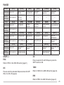
Amateur satellites receive on one band and transmit on
another. This transceiver can handle uplink/ downlink
frequency combinations simultaneously as shown below.
While in the Satellite mode, group A–2 keys are changed
as follows.
UPLINK
Band
HF ~
50 MHz
HF ~
50 MHz
DOWN
LINK
430/
144 MHz
440 MHz
√
144 MHz
√
430/
440 MHz
√
√
1.2 GHz
√
√
1.2 GHz
√
√
√
√
√
√
ENTERING THE SATELLITE MODE
1 Press [F1] (1 s) until you select group B.
Action
[A–2]
Press the Move to
A–3
key:
Press and
Move to
hold the
group B
key:
[M/S]
[T.REV]
Swap
T.REV
MAIN
ON/ OFF
and SUB
—
—
[TRACE]
—
—
[XIT]
TRACE XIT
ON/ OFF ON/ OFF
—
Clear XIT
offset
M/S
Press to swap the main band frequency with the sub
band frequency.
T.REV
While the TRACE function is ON, press to toggle the
Trace Reverse function ON or OFF.
2 Confirm that you have selected group B–1.
•
If B–1 is not selected, press [F1] until you select
B–1.
3 Press [SATL].
TRACE
Press to switch the Trace function ON or OFF.
XIT
Press to switch the XIT function ON or OFF. Press and
hold to clear the XIT offset frequency.
31
BASIC OPERATION
When you enter the Satellite mode, you are always
controlling one of 10 Satellite Memory channels with the
adjustable frequency function. The Satellite Memory
channel number (0 ~ 9) appears above the main band
frequency display when you enter this mode.
1 Press [SATL] while in group B–1 to enter Satellite
mode.
• The default downlink (435.9 MHz) and uplink
(145.9 MHz) frequencies appear.
• “TRC”, “R”, and “SATL” appear to indicate the current
selections.
6 To adjust the frequency on the sub-band display:
Press [M/S] while in group A–2 to swap the main
band with the sub-band frequency, then turn the
Tuning or MULTI/ CH control. The following table
shows which control to use when adjusting
frequencies with tracing ON and OFF.
Press to toggle
TRACE/
TRACE/
the mode
TRACE R ON TRACE R OFF
Tuning control
Main and Sub
Main
(“TUN”)
MULTI/ CH
Main and Sub
Main
control (“MLTI”)
2 On VFO A, tune to the downlink (RX) frequency of the
satellite.
STORING SATELLITE MEMORY CHANNELS
3 Press or press and hold [MODE] while in group A–1
to select the desired operating mode.
You can store all the above settings to one of 10 Satellite
memory channels for future operations.
4 As the Satellite moves, fine tune to the changing
downlink (RX) frequency of the satellite using the
Tuning control (adjusting the Doppler effect).
1 Press [M.IN] while in group A–4, then turn the MULTI/
CH control to select a channel from 0 to 9.
• As you adjust the downlink (RX) frequency, the Trace
function automatically changes the uplink frequency so
that the sum of the two frequencies is kept the same
(Reverse Trace).
• If necessary, press [TRACE] while in group A–2 to quit
the Trace function. “TRC” disappears.
• The trace function can also change the uplink (TX)
frequency so that the difference between the two
frequencies is kept the same (Normal Trace).
5 If you want to switch to the normal trace mode, press
[T.REV] while in group A–2. “R” disappears.
32
2 Press [M.IN] again to store the selection to the
memory channel. To quit, press [CLR].
Note: The Satellite Memory channel does not hold the frequency
adjustment values when the channel is changed. So, when you change
the channel number or switch the transceiver OFF, the adjusted
frequency values are cleared unless you stored it by pressing [M.IN].
RECALLING A SATELLITE MEMORY CHANNEL
1 Press [V/M] while in group A–4.
2 Turn the MULTI/ CH control to select your desired
Satellite Memory channel.
3 Press [V/M] to return to the frequency adjustment
mode. If necessary, press the Tuning control to
toggle between the Tuning and MULTI/ CH control.
SATELLITE CHANNEL NAME
You can name each Satellite Memory channel using a
maximum of 8 alpha-numeric characters. First, store the
settings to the Satellite Memory channel {above}.
1 Press [M.IN] while in group A–4, then turn the
MULTI/ CH control to select your desired Satellite
Memory channel.
2 Press [MN.IN].
•
An entry cursor appears.
3 Select a character by turning the MULTI/ CH control,
[]/ [a
a]. Press [M.SR]
then move the cursor using [[
to go back to Memory Scroll mode. Press [DEL] to
erase the character at the cursor. You can also use
the optional MC-52DM microphone to enter a name
{TS-2000 page 63}.
4 Press [OK] to store the name to the Satellite Memory
channel. Press [CLR] to quit.
5 The stored Satellite Memory name appears above the
main band frequency display on the RC-2000.
Memory in Satellite mode, press [Q.IN] (L2). The
settings are stored to Satellite Memory channel 9.
To recall the Quick Memory, press [Q.M] while in group
B–4 or press [V/M] while in group A–2, then turn the
MULTI/ CH control to recall the Satellite Memory
channel 9.
CHECKING THE UPLINK FREQUENCY
When you need to monitor the uplink (TX) frequency,
press [M/S] while in group A–2. Each time you press
[M/S], the uplink (TX) frequency and the downlink (RX)
frequency are swapped.
USING XIT/ RIT IN SATELLITE MODE
You can also use the RIT or XIT function while in the
Satellite mode. Press [RIT] (R2) or [XIT] while in group
A–2 to activate the function. When the RIT or XIT
function is ON, the sub-band frequency display shows
the current RIT or XIT offset frequency instead of the
operating frequency. To clear the RIT or XIT offset
frequency, press and hold [RIT] or [XIT].
Note: You cannot activate both the RIT and XIT functions at the same
time in the Satellite mode.
CHANGING THE FREQUENCY BAND
QUICK MEMORY IN SATELLITE MODE
While in the Satellite mode, only 1 Quick Memory
channel is available. It uses Satellite Memory channel 9
to store the settings. To store the settings to the Quick
Press [M/S] while in group A–3 to select the band you
want to change on the main band, then press [UP]/
[DOWN] while in group A–1 to select the band you want
to operate. Press [M/S] again to swap the bands.
33
EASY VIEWING MODE
OVERVIEW
KEYS (F1 ~ F6)
Since the RC-2000 is designed to be used in a vehicle, it
has an unique Easy Viewing mode for mobile operation.
When you enter this mode, the display shows only the
current Control band frequency in a large font. Also,
only 2 key function groups are available for quick
function access. Unlike normal mode, 2 key function
groups can be toggled by simply pressing [F1].
Press [F1] to toggle between 2 groups. “F” appears for
the first key group. “F” appears for the second key
group.
[F]
OPERATION
While operating in the regular VFO mode or Memory
Recall mode:
[F]
The frequency and operating mode of the current
Control band is displayed in a large font.
•
To change the Control band, press either the
MAIN AF control or the SUB AF control.
•
To toggle the available key functions, press [F1].
[CLR]
Toggle
Exit or
the group clear
Press [EASY] (L3) to enter the Easy Viewing mode.
•
[MODE]
[PF]
[1MHz]
[DOWN]
[M>V]
[MENU]
Copy the Enter
memory Menu
data to a mode
VFO
[M.IN]
Store the
data to a
Memory
channel
MODE
Refer to the [MODE] instructions {page 15}.
PF
Refer to the [PF] instructions {page 16}.
1MHz
Refer to the [1MHz] instructions {page 15}.
DOWN
Refer to the [DOWN] instructions {page 15}.
34
[UP]
Toggle
Change Program- 1MHz Up/ Move
Move up
the group the mode mable
Down
down the the band
Function
band
[V/M]
Toggle
VFO and
Memory
channel
UP
Refer to the [UP] instructions {page 15}.
CLR
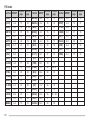
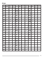
Refer to the [CLR] instructions {page 16}.
KEYS (L1 ~ L3)
AT/ AT IN/ AT R IN (L1 key)
Press to activate the Automatic Antenna Tuner function
for the HF ~ 50 MHz bands. When it is in-line, [AT IN] or
[AT R IN] appears {page 10}.
M>V
Refer to the [M>V] instructions {page 16}.
CALL (L1 key)
Refer to the [MENU] instructions {page 16}.
Appears only when you operate the 144 MHz ~ 1.2 GHz
bands. Press to recall the Call channel for the current
operating band {page 10}.
M.IN
RIT (L2 key)
Refer to the [M.IN] instructions {page 17}.
Press to activate the RIT function. Turn the RIT/ SUB
control to adjust the offset frequency. Press and hold the
key to clear the offset {page 12}.
MENU
V/M
Refer to the [V/M] instructions {page 17}.
XIT (L2 key)
Press to activate the XIT function. Turn the RIT/ SUB
control to adjust the offset frequency. Press and hold the
key to clear the offset {page 15}.
OFF (L3 key)
Exit the Easy Viewing mode.
35
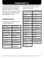
CHANGING THE FONT STYLE
While you are in Easy Viewing mode, two different types
of font styles are available. To change the font:
1 Press [MENU].
2 Turn the MULTI/ CH control to select Menu No. 58.
3 Press [+]/ [–] to select “FONT2” or “FONT1” (default).
4 Press [OK] to accept the change.
FONT1
FONT2
Note: Changing the font in the Easy Viewing mode does not change the
font in the normal display mode.
36
PACKET CLUSTER TUNE
PACKET CLUSTER TUNE FUNCTION
DX Packet Cluster is a packet network consisting of
nodes and stations who are interested in DXing and
contesting. If one station finds a DX station on the air,
he or she sends a notice to his or her node. This node
then passes the information to all its local stations as
well as to another node. This transceiver can display
received DX information and hold the latest information
on up to 10 DX stations.
6 If you are not using the Auto Tune function, press
[SET] (L3).
• The main transceiver is tuned to the frequency of the
reported DX station on the sub-receiver’s display.
NORMAL P.C.T. MODE
• Transmitting on the tuned frequency, the transceiver
exits the P.C.T. mode. Press [P.C.T.] again to reactivate
it if necessary.
1 Press [A/B] while in group A–2 to select VFO A or
VFO B on the main transceiver.
• In order to use the Auto Tune function, access Menu
No. 49A and select “AUTO”; the default is “MANUAL”.
2 Press and hold the SUB AF control to switch the subreceiver ON, if the sub-receiver is switched OFF.
7 Press [P.C.T.] while in group B–1 to exit the P.C.T.
mode.
3 Tune to the frequency of the target DX Packet Cluster
node on the sub-receiver.
4 Press [MENU] while in group A–3, then turn the
MULTI/ CH control to select Menu No. 46. Confirm
that “SUB” is selected. If not, press [+] to select
“SUB”.
5 Press [P.C.T.] while in group B–1 to enter the Packet
Cluster Tune (P.C.T.) mode.
• Each time new DX Packet Cluster data is received, the
DX station’s callsign, in Morse code, sounds and the
information is displayed on the sub-band display.
37
LIST FUNCTION IN P.C.T. MODE
NEW PACKET CLUSTER DATA
To access your desired DX information from the P.C.T
memory in the P.C.T. mode:
The transceiver can be set to output a beep instead of a
Morse code when new DX Packet Cluster data is
received. Press [MENU] while in group A–3, then turn
the MULTI/ CH control to select Menu No. 49. Press
[SUB], then turn the MULTI/ CH control to access Menu
No. 49B. Select “OFF”. “VOICE” can also be set when
you install the optional VS-3 {TS-2000 page 91}.
1 Press [LIST] (L2).
2 Press [c]/ [d] or turn the MULTI/ CH control to
select the report.
•
“s” indicates which DX report is currently
selected.
3 Press [SET] to tune the main transceiver to the
reported frequency.
38
•
Press [DEL] to erase the selected DX information
from the P.C.T. memory. Press [EXIT] to return to
normal P.C.T. information display.
•
Press [OK] to view all the comments of the
selected DX station.
Note:
◆ You cannot send DX information to a node using the P.C.T. mode.
◆ The DX Packet Cluster data in memory is retained when the
transceiver is turned OFF. However, the sub-receiver’s frequency
display returns to the receiving frequency of the DX Packet Cluster
node.
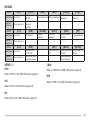
VISUAL SCAN
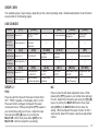
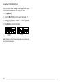
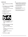
SELECTING THE NUMBER OF CHANNELS
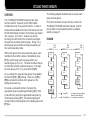
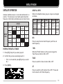
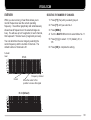
OVERVIEW
While you are receiving, Visual Scan allows you to
monitor frequencies near the current operating
frequency. Visual Scan graphically and simultaneously
shows how all frequencies in the selected range are
busy. You will see up to 21 segments, for each channel,
that represent 7 S-meter levels (3 segments per level).
You can determine the scan range by selecting the
center frequency and the number of channels. The
default number of channels is 61.
S-meter
level
1 Press [F1] (1 s) until you select group A.
2 Press [F1] until you select A–3.
3 Press [MENU].
4 Turn the MULTI/ CH control to select Menu No. 11.
5 Press [+]/ [–] to select 31, 61 (default), 91, or
181.
6 Press [OK] to complete the setting.
31 ch
7
6
5
4
3
2
1
Frequency channel
Cursor
Move the cursor to this
position to receive this signal
61 ch (Default)
7
6
5
4
3
2
1
39
USING VISUAL SCAN
1 Select your desired frequency using the Tuning
control.
2 Turn the Tuning control or press Mic [UP]/ [DWN]
to select the operating frequency.
• This frequency will be used as the center frequency
for the Visual Scan.
3 Press [F1] (1 s) until you select group B.
4 Press [F1] until you select B–3.
5 Press [VISUAL] to start the Visual Scan.
• To pause the Scan, press [PAUSE]. “P” appears on
the display. Press [PAUSE] again to resume
scanning.
6 To change the center frequency, turn the Tuning
control or press Mic [UP]/ [DWN].
• The displayed frequency changes and the cursor
moves.
• Press [SET] to use the changed operating frequency
as the center frequency.
• Press [RESET] to restore the original center
frequency.
7 To quit Visual Scan, press [EXIT].
40
Note:
◆ You can press the Tuning control to change the Tuning control
and MULTI/ CH control to adjust the operating frequency. “TUN”
or “MLTI” appears to indicate which control mode is selected.
◆ If you start Visual Scan in Memory Recall mode, the memory
channel frequencies will be scanned.
◆ Visual Scan stops while transmitting.
◆ During the Visual Scan, the scanning frequency cannot be
monitored through the speaker.
◆ Depending on conditions, Visual Scan and the conventional
S-meter may indicate different signal strength levels.
PROGRAMMABLE MEMORY (PM)
Programmable Memory (PM) stores virtually all settings
currently set on the transceiver. This transceiver
provides 5 PM channels to store 5 sets of transceiver
configurations. Later you can quickly recall one of these
memories, depending on the operations you have in
mind or the operating environment.
The following settings are shared by both the main
transceiver and the sub-receiver:
1MHz Up/ Down ON/ OFF
1MHz Up/ Down frequency
step
AT ON/ OFF
AGC ON/ OFF
Satellite mode ON/ OFF
VOX ON/ OFF
PROGRAMMABLE INFORMATION
CW break-in ON/ OFF
FINE ON/ OFF
The following settings can be separately stored for the
main transceiver and sub-receiver:
RIT/ XIT ON/ OFF
Sub-receiver ON/ OFF
N.B. ON/ OFF
N.B. level
VFO A/ B frequency
VFO A/ B selection
A.N./ B.C. ON/ OFF
A.N./ B.C. level data
Operating mode (MAIN)
VFO frequency (SUB)
M.B.C. ON/ OFF
M.B.C. frequency data
Operating mode (SUB)
N.R. 1 level
TX monitor level
Carrier level
Memory Group setting
Signalling settings (FM)
Output power
VOX gain level
ANT 1 or ANT 2
Break-in delay
VOX delay time
Mic gain level
Electric keyer speed
ATT/ PRE ON/ OFF
Speech Processor level
Dimmer level
ASC ON/ OFF
Scanning speed
Beep level
Negative/ Positive display
Visual Scan mode
Noise Reduction setting
Contrast level
Auto mode ON/ OFF
Repeater offset frequency
MULTI/ CH control
frequency step
Display status when it is
switched OFF
41
APPLICATION EXAMPLES
The following are examples of how you might use Programmable Memory.
Solution
Solution
Situation
Situation 11
You share your transceiver with other members in
your family or club. However, each individual has
personal preferences for how they like to set various
functions. You have to keep changing many settings
each time you use the transceiver.
Situation
Situation 22
While operating mobile on the way to work every
morning, you prefer a silent transceiver that does not
interrupt the morning calm. In addition, you feel that a
bright display is a waste of electricity in sunlight.
At night when driving home, you realize the Beep
function truly serves a purpose and you feel it is nice
to see a bright display after dark.
Because 5 PM channels are available, up to
5 persons can separately program the transceiver and
store their customized environment. Then each
person can quickly change to his or her favorite
settings simply by recalling a PM channel.
It is too much trouble to change back the settings
after somebody else has reconfigured them. So this
application may avoid having a feature-rich
transceiver but never using many useful features.
Solution
Solution
In two PM channels, store the same operating data
such as frequency, offset, tone, etc., and store
different settings for the Display Dimmer and Beep
functions. Then you can quickly recall the best
settings for day or night operating.
PM CHANNEL DEFAULT VALUES
The default values of the PM channels are set as follows.
PM Channel
PM1
PM2
PM3
PM4
PM5
42
Freq. and Mode (MAIN)
14 MHz/ USB
21 MHz/ USB
50 MHz/ USB
144 MHz/ FM
430 or 440 MHz/ FM
Freq. and Mode (SUB)
144 MHz/ FM
144 MHz/ FM
430 or 440 MHz/ FM
144 MHz/ FM
430 or 440 MHz/ FM
Display
Negative
Positive
Negative
Negative
Positive
Dimmer
3
3
3
2
2
Beep
4
4
4
4
4
Key Group
A–1
A–2
A–3
B–1
B–3
STORING DATA IN PM CHANNELS
RECALLING A PM CHANNEL
1 Confirm that the following conditions have been
satisfied:
1 Press [PM].
• The transceiver is in the receive mode.
• PM channel numbers 1 to 5 appear at the bottom of the
display.
• Scan is not being used.
• The Microphone Control is OFF.
2 Configure the transceiver as you like.
• For the items that can be stored, see page 41.
3 Press [PM], [P.IN].
• PM channel numbers 1 to 5 appear and blink at the
bottom of the display.
2 Press [1] to [5] corresponding to your desired PM
channel.
• The contents of the selected PM channel are recalled.
• The recalled PM channel number appears in the upper
right corner.
• To exit PM Recall mode, press [PM], then press [OFF].
Note: You cannot recall a PM channel while transmitting.
4 Press [1] to [5] corresponding to your desired PM
channel.
• The settings listed on page 41 are stored in the PM
channel.
• Press [OFF] to cancel.
AUTO PM CHANNEL SAVE
After you recalled a PM channel, the function
automatically overwrites the current PM channel with the
present operating environment when:
• You recall another PM channel.
• You press [OFF] in PM channel recall mode.
• You switch the transceiver OFF.
Note: You cannot switch this function OFF.
43
SKY COMMAND II+ (K-TYPE ONLY)
The Sky Command II+ allows you to remotely control a
TS-570, TS-870, or TS-2000 series HF transceiver from
a separate location. Before operating Sky Command II+
with the RC-2000, read the Sky Command II+ section of
the TS-2000(X)/ TS-B2000 instruction manual, starting
on page 83. After completing the setup, refer to pages
84 ~ 88 of the TS-2000(X)/ TS-B2000 instruction manual
for the control operations using a TM-D700A, TH-D7A,
or another TS-2000(X) transceiver.
8 Turn the Tuning control to select a character.
PROGRAMMING CALL SIGNS
1 Press [F1] (1 s) until you select group A.
The TS-2000(X)/ TS-B2000 can serve as either
Commander or Transporter. Program the same callsign
for both Commander and Transporter. Refer to page 83
of the TS-2000/ TS-B2000 instruction manual for the
possible callsign entries.
2 Press [F1] until you select A–3.
On the TRANSPORTER:
1 Press [F1] (1 s) until you select group A.
2 Press [F1] until you select A–3.
3 Press [MENU].
4 Turn the MULTI/ CH control to select Menu No. 62.
5 Press [SUB].
6 Turn the MULTI/ CH control to select Menu No. 62A.
7 Press [OK].
• The Commander callsign entry prompt appears.
• You can enter 0 to 9, A to Z, and –.
b]/ [a
a] to move the cursor. Press [DEL] to
9 Press [b
delete the character at the cursor. Press [CLR] to
cancel the entry.
10 Press [OK] to store the callsign.
On the COMMANDER:
3 Press [MENU].
4 Turn the MULTI/ CH control to select Menu No. 62.
5 Press [SUB].
6 Turn the MULTI/ CH control to select Menu No. 62B.
7 Press [OK].
• The Transporter callsign entry prompt appears.
8 Turn the Tuning control to select a character.
• You can enter 0 to 9, A to Z, and –.
b]/ [a
a] to move the cursor. Press [DEL] to
9 Press [b
delete the character at the cursor. Press [CLR] to
cancel the entry.
•
The callsign must match the Transporter callsign
to perform Sky Command II+ operation.
10 Press [OK] to store the callsign.
44
PROGRAMMING A TONE FREQUENCY
6 Turn the MULTI/ CH control to select Menu No. 62D.
You must also program the CTCSS tone to operate the
Sky Command II+. Select the same CTCSS tone for
both the Commander and the Transporter.
7 Press [–]/ [+] to select either 1200 bps or 9600 bps.
1 Press [F1] (1 s) until you select group A.
2 Press [F1] until you select A–3.
3 Press [MENU].
4 Turn the MULTI/ CH control to select Menu No. 62.
8 Press [OK] to store the TNC communication speed
for the Sky Command II+ operation. Press [CLR] to
cancel the selection.
Note: 9600 bps can be used only when you use TS-2000(X)/ TS-B2000
for both the Commander and the Transporter.
CONFIGURING A TNC BAND
5 Press [SUB].
If you are using a TS-2000(X)/ TS-B2000, confirm that
the built-in TNC is assigned to the sub-receiver.
6 Turn the MULTI/ CH control to select Menu No. 62C.
1 Press [F1] (1 s) until you select group A.
7 Press [–]/ [+] to select a CTCSS tone frequency for
the Sky Command II+ operation.
2 Press [F1] until you select A–3.
8 Press [OK] to store the CTCSS tone frequency for
the Sky Command II+ operation. Press [CLR] to
cancel the selection.
4 Turn the MULTI/ CH control to select Menu No. 46.
PROGRAMMING COMMUNICATION SPEED
6 Press [OK] to store the TNC band for the Sky
Command II+ operation. Press [CLR] to cancel the
selection.
You must configure the same TNC communication speed
between the Commander and the Transporter.
3 Press [MENU].
5 Press [–]/ [+] to select “SUB”.
1 Press [F1] (1 s) until you select group A.
2 Press [F1] until you select A–3.
3 Press [MENU].
4 Turn the MULTI/ CH control to select Menu No. 62.
5 Press [SUB].
45
STARTING SKY COMMAND II+ OPERATION
TO EXIT SKY COMMAND II+ OPERATION
1 Select an open 144 MHz frequency on the main
transceiver.
1 Press [MENU].
2 Select an open 440 MHz frequency for the subreceiver.
3 Press [F1] (1 s) until you select group A.
4 Press [F1] until you select A–3.
5 Press [MENU].
6 Turn the MULTI/ CH control to select Menu No. 62.
7 Press [SUB].
8 Turn the MULTI/ CH control to select Menu No. 62E.
9 Press [–]/ [+] to select either “COMMAND”
(Commander) or “T-PORTER” (Transporter).
10 The Sky Command II+ operation starts.
Note: “CLIENT” is used when you use another TM-D700A or TH-D7A for
the Transporter of the Sky Command operation. Refer to “USING A
SEPARATE TRANSPORTER” {TS-2000 page 88}.
46
2 Press [–]/ [+] and select “OFF” to exit the Sky
Command II+ operation.
QUICK KEY REFERENCE
USB/ LSB mode
RC-2000 TS-2000
Function
page
page
[A/B]
A–2
15
18
[MENU]
A–3
16
21
[SET]
A–5
17
67
[A=B]
A–2
15
38
[METER]
B–4
20
19
[SG SEL]
B–3
20
69
[AGC]
A–3
16
38, 103 [MG SEL]
A–4
16
64
[SPLIT]
A–2
15
31
[A.N.]
C–3
22
C–1
21
28
[STEP]
A–3
16
37
[MIC]
GROUP
RC-2000 TS-2000
page
page
GROUP
56
GROUP
RC-2000 TS-2000
Function
page
page
Function
[ANT1/2]
B–1
19
72
[M.IN]
A–4
17
58
[TF SET]
A–2
15
31
[ATT]
B–1
19
57, 73
[MODE]
A–1
15
19
[T-MON]
C–1
22
79
[AUTO]
B–3
20
73
[M>V]
A–4
16
61
[UP]
A–1
15
10
[B.C.]
C–3
22
56
[NB]
A–3
16
57
[VISUAL]
B–3
39
70
[CH1]
B–2
19
89
[N.R.]
C–3
22
56
[V DLY]
C–2
22
39
[CH2]
B–2
19
89
[OPEN]
A–5
17
62
[V GAIN]
C–2
22
39
[CH3]
B–2
19
89
[P.C.T.]
B–1
37
53
[V/M]
A–4
17
59
[CLOSE]
A–5
17
62
[PF]
A–3
16
77
[VOX]
C–2
22
39
[CLR]
A–4
16
10, 62
[PRE]
B–1
19
57
[XIT]
A–2
15
40
[CTRL]
B–4
20
45
[PROC]
C–1
21
40
[1MHz]
A–1
15
37
[DOWN]
A–1
15
10
[PWR]
C–1
22
20, 79
[DUAL]
B–4
20
45
[Q.M]
B–4
20
65
[FILTER]
C–3
24
55
[REC]
B–2
19
89
[FINE]
A–1
15
38
[RF]
C–2
24
18
[LOCK]
B–4
20
—
[SATL]
B–1
19, 31
53
[M.B.C.]
C–3
24
56
[SCAN]
B–3
20
66 ~ 69
47
CW mode
RC-2000 TS-2000
Function
page
page
GROUP
RC-2000 TS-2000
Function
page
page
GROUP
RC-2000 TS-2000
page
page
Function
GROUP
[A/B]
A–2
15
18
[LOCK]
B–4
20
—
[SCAN]
B–3
20
66 ~ 69
[A=B]
A–2
15
38
[M.B.C.]
C–3
24
56
[SET]
A–5
17
67
[AGC]
A–3
16
38, 103
[MENU]
A–3
16
21
[SG SEL]
B–3
20
69
[ANT1/2]
B–1
19
72
[METER]
B–4
20
19
[SPLIT]
A–2
15
31
[ATT]
B–1
19
57, 73
[MG SEL]
A–4
16
64
[STEP]
A–3
16
37
[AUTO]
B–3
20
73
[M.IN]
A–4
17
58
[TF SET]
A–2
15
31
[BK DLY]
C–2
24
42
[MODE]
A–1
15
19
[UP]
A–1
15
10
[CH1]
B–2
19
43
[M>V]
A–4
16
61
[VISUAL]
B–3
39
70
[CH2]
B–2
19
43
[NB]
A–3
16
57
[V/M]
A–4
17
59
[CH3]
B–2
19
43
[N.R.]
C–3
22
56
[VOX]
C–2
24
42
[CLOSE]
A–5
17
62
[OPEN]
A–5
17
62
[XIT]
A–2
15
40
[CLR]
A–4
16
10, 62
[P.C.T.]
B–1
37
53
[1MHz]
A–1
15
37
[CTRL]
B–4
20
45
[PF]
A–3
16
77
[CAR]
C–1
23
30
[PRE]
B–1
19
57
[CW TUN]
C–1
23
30
[PWR]
C–1
22
20, 79
[DOWN]
A–1
15
10
[Q.M]
B–4
20
65
[DUAL]
B–4
20
45
[REC]
B–2
19
43, 89
[FILTER]
C–3
24
55
[REV]
C–1
23
—
[FINE]
A–1
15
38
[RF]
C–2
24
18
[KEY]
C–2
24
42
[SATL]
B–1
19, 31
53
48
FM mode
RC-2000 TS-2000
Function
page
page
GROUP
RC-2000 TS-2000
Function
page
page
GROUP
RC-2000 TS-2000
page
page
Function
GROUP
[A/B]
A–2
15
18
[LOCK]
B–4
20
—
[RF]
C–2
24
18
[A=B]
A–2
15
38
[M.B.C.]
C–4
24
56
[SATL]
B–1
19, 31
53
[AGC]
A–3
16
38, 103
[MENU]
A–3
16
21
[SCAN]
B–3
20
66 ~ 69
[ALT]
C–3
26
72
[METER]
B–4
20
19
[SET]
A–5
17
67
[ANT1/2]
B–1
19
72
[MG SEL]
A–4
16
64
[SG SEL]
B–3
20
69
[ASC]
C–1
25
34
[M.IN]
A–4
17
58
[SHIFT]
C–3
26
32
[ATT]
B–1
19
57, 73
[MODE]
A–1
15
19
[SPLIT]
A–2
15
31
[AUTO]
B–3
20
73
[M>V]
A–4
16
61
[STEP]
A–3
16
37
[CH1]
B–2
19
89
[NAR]
C–2
26
29
[TF SET]
A–2
15
31
[CH2]
B–2
19
89
[NB]
A–3
16
57
[T-MON]
C–1
22
79
[CH3]
B–2
19
89
[N.R.]
C–4
22
56
[TONE]
C–3
26
33
[CLOSE]
A–5
17
62
[OPEN]
A–5
17
62
[T.SEL]
C–4
26
33
[CLR]
A–4
16
10, 62
[P.C.T.]
B–1
37
53
[UP]
A–1
15
10
[CTRL]
B–4
20
45
[PF]
A–3
16
77
[VISUAL]
B–3
39
70
[CTCSS]
C–3
26
35
[PRE]
B–1
19
57
[V DLY]
C–2
22
39
[DCS]
C–3
26
36
[PROC]
C–1
21
40
[V GAIN]
C–2
22
39
[DOWN]
A–1
15
10
[PWR]
C–1
22
20, 79
[V/M]
A–4
17
59
[DUAL]
B–4
20
45
[Q.M]
B–4
20
65
[VOX]
C–2
22
39
[FILTER]
C–4
24
55
[REC]
B–2
19
89
[XIT]
A–2
15
40
[FINE]
A–1
15
38
[REV]
C–1
25
34
[1MHz]
A–1
15
37
49
FSK mode
RC-2000 TS-2000
Function
page
page
GROUP
RC-2000 TS-2000
Function
page
page
GROUP
RC-2000 TS-2000
page
page
Function
GROUP
[A/B]
A–2
15
18
[METER]
B–4
20
19
[SPLIT]
A–2
15
31
[A=B]
A–2
15
38
[MG SEL]
A–4
16
64
[STEP]
A–3
16
37
[AGC]
A–3
16
38, 103
[M.IN]
A–4
17
58
[TF SET]
A–2
15
31
[ANT1/2]
B–1
19
72
[MODE]
A–1
15
19
[T-MON]
C–1
27
79
[ATT]
B–1
19
57, 73
[M>V]
A–4
16
61
[UP]
A–1
15
10
[AUTO]
B–3
20
73
[NB]
A–3
16
57
[VISUAL]
B–3
39
70
[CAR]
C–1
23
51
[N.R.]
C–3
22
56
[V/M]
A–4
17
59
[CH1]
B–2
—
—
[OPEN]
A–5
17
62
[XIT]
A–2
15
40
[CH2]
B–2
—
—
[P.C.T.]
B–1
37
53
[1MHz]
A–1
15
37
[CH3]
B–2
—
—
[PF]
A–3
16
77
[CLOSE]
A–5
17
62
[PRE]
B–1
19
57
[CLR]
A–4
16
10, 62
[PWR]
C–1
22
20, 79
[CTRL]
B–4
20
45
[Q.M]
B–4
20
65
[DOWN]
A–1
15
10
[REC]
B–2
—
—
[DUAL]
B–4
20
45
[REV]
C–1
27
51
[FILTER]
C–3
24
55
[RF]
C–2
24
18
[FINE]
A–1
15
38
[SATL]
B–1
19, 31
53
[LOCK]
B–4
20
—
[SCAN]
B–3
20
66 ~ 69
[M.B.C.]
C–3
24
56
[SET]
A–5
17
67
[MENU]
A–3
16
21
[SG SEL]
B–3
20
69
50
AM mode
RC-2000 TS-2000
Function
page
page
GROUP
RC-2000 TS-2000
page
page
GROUP
[A/B]
A–2
15
18
[MENU]
A–3
16
21
[SCAN]
B–3
20
66 ~ 69
[A=B]
A–2
15
38
[METER]
B–4
20
19
[SET]
A–5
17
67
38, 103 [MG SEL]
GROUP
RC-2000 TS-2000
Function
page
page
Function
[AGC]
A–3
16
A–4
16
64
[SG SEL]
B–3
20
69
[ANT1/2]
B–1
19
72
[MIC]
C–1
21
29
[SPLIT]
A–2
15
31
[ATT]
B–1
19
57, 73
[M.IN]
A–4
17
58
[STEP]
A–3
16
37
[AUTO]
B–3
20
73
[MODE]
A–1
15
19
[TF SET]
A–2
15
31
[B.C.]
C–3
22
56
[M>V]
A–4
16
61
[T-MON]
C–1
22
79
[CAR]
C–1
23
29
[NAR]
C–2
30
29
[UP]
A–1
15
10
[CH1]
B–2
19
89
[NB]
A–3
16
57
[VISUAL]
B–3
39
70
[CH2]
B–2
19
89
[N.R.]
C–3
22
56
[V DLY]
C–2
22
39
[CH3]
B–2
19
89
[OPEN]
A–5
17
62
[V GAIN]
C–2
22
39
[CLOSE]
A–5
17
62
[P.C.T.]
B–1
37
53
[V/M]
A–4
17
59
[CLR]
A–4
16
10, 62
[PF]
A–3
16
77
[VOX]
C–2
22
39
[CTRL]
B–4
20
45
[PRE]
B–1
19
57
[XIT]
A–2
15
40
[DOWN]
A–1
15
10
[PROC]
C–1
21
40
[1MHz]
A–1
15
37
[DUAL]
B–4
20
45
[PWR]
C–1
22
20, 79
[FILTER]
C–3
24
55
[Q.M]
B–4
20
65
[FINE]
A–1
15
38
[REC]
B–2
19
89
[LOCK]
B–4
20
—
[RF]
C–2
24
18
[M.B.C.]
C–3
24
56
[SATL]
B–1
19, 31
53
51
MAINTENANCE
GENERAL INFORMATION
SERVICE NOTE
This product has been factory aligned and tested to
specification before shipment. Attempting service or
alignment without factory authorization can void the
product warranty.
If you desire to correspond on a technical or operational
problem, please make your note legible, short, complete,
and to the point. Help us help you by providing the
following:
• Model name
SERVICE
When returning this product to your dealer or service
center for repair, pack it in its original box and packing
material. Include a full description of the problem(s)
experienced. Include your telephone number along with
your name and address in case the service technician
needs to call you; if available, also include your fax
number and e-mail address. Don’t return accessory
items unless you feel they are directly related to the
service problem.
You may return this product for service to the authorized
KENWOOD dealer from whom you purchased it, or any
authorized KENWOOD service center. Please do not
send subassemblies or printed circuit boards only. Send
the complete product. A copy of the service report will
be returned with the product.
52
• Question or problem you are having
• Other equipment in your station pertaining to the problem
Do not pack the equipment in crushed newspapers for shipment!
Extensive damage may result during rough handling or shipping.
Note:
Record the date of purchase and the name of the dealer from whom
this product was purchased.
◆ For your own information, retain a written record of any maintenance
performed on this product.
◆ When claiming warranty service, please include a photocopy of the
bill of sale or other proof-of-purchase showing the date of sale.
◆
CLEANING
To clean the case of this product, use a neutral detergent
(no strong chemicals) and a damp cloth.
SPECIFICATIONS
RC-2000 MOBILE CONTROLLER
General
RC-2000 Control Panel
Supply Voltage
9.5 V DC ±0.5 V
Current
Less than 200 mA
Usable temperature range
–20°C ~ +60°C (–4°F ~ +140°F)
Dimension (W x H x D Projections included)
140 x 60 x 49.3 mm/ 5.5" x 2.4" x 2.0"
Weight
Approx. 180 g/ 0.4 lb
EXTERNAL SPEAKER
General
External Speaker
Speaker impedance
4Ω ±15 %
Input power
3 W (nominal), 5 W (maximum)
Output audio level
85 ±2 dB/ W
Frequency response
300 ~ 9000 Hz
Dimension (W x H x D Projections included)
113 x 66 x 58.5 mm/ 4.5" x 2.6" x 2.3"
Weight
Approx. 360 g/ 0.79 lb
53
APPENDIX
RESETTING MEMORY DATA
You can reset the stored memory data to the factory
default values if necessary. By performing the reset, you
will lose all the relative contents of memory data. So, we
recommend you write down any important memory data
before performing the reset. To perform the reset, first
switch the transceiver OFF.
Instruction
Function
Press
[R1]+
[ ] (POWER)
Resets the contents of PM
(Programmable Memory) to the
factory default values {page 42}.
Press
[L2]+
[ ] (POWER)
Performs a Partial Reset
{TS-2000 page 92}.
Press
[L3]+
[ ] (POWER)
Performs a Full Reset
{TS-2000 page 92}.
1 Press [F1]+[ ] (POWER) on the RC-2000 to switch
the transceiver ON.
2 To exit the demonstration mode, first turn the
transceiver OFF, then press [F1]+[ ] (POWER) on
the RC-2000 to turn the transceiver ON.
Note: You cannot exit the demonstration mode by simply switching the
transceiver OFF or performing a full reset {TS-2000 page 92}.
CONFIGURING THE AUTO MODE FREQUENCY TABLE
To configure the Auto Mode frequency table:
1 Press [F6]+[ ] (POWER) on the RC-2000 to switch
the transceiver ON.
2 Use the following controls to configure the table.
Tuning control: Adjust the frequency
MULTI/ CH control: Change the channel number
[MODE]/ [REV]: Change the operating mode
[UP]/ [DWN]/ [1MHz]: Change the operating band
When a confirmation message appears, press [OK] to
proceed. Otherwise, press any other key to cancel the
operation.
3 Press [OK] to store the settings.
DEMONSTRATION MODE
The RC-2000 control panel can be used in place of the
TM-D700A/E panel. Switch the TM-D700A/E OFF then
remove the TM-D700A/E panel. Plug the RC-2000
panel and press [ ] (POWER). The RC-2000 panel
automatically detects the TM-D700A/E transceiver and
will operate the same as the original TM-D700A/E panel.
The RC-2000 mobile controller and the transceiver can
be configured to enter demonstration mode for display
purposes. To enter the demonstration mode:
54
CONCERNING THE TM-D700A/E PANEL
NOTICES TO THE USER
CAUTIONS
One or more of the following statements may be
applicable:
Please observe the following cautions to prevent fire,
personal injury, and transceiver damage:
FCC WARNING
•
This equipment generates or uses radio frequency energy. Changes or
modifications to this equipment may cause harmful interference unless
the modifications are expressly approved in the instruction manual. The
user could lose the authority to operate this equipment if an unauthorized
change or modification is made.
Do not attempt to configure your transceiver while
driving; it is too dangerous.
•
Be aware of local laws pertaining to the use of
headphones/headsets while driving on public
roads. If in doubt, do not wear headphones while
mobiling.
INFORMATION TO THE DIGITAL DEVICE USER REQUIRED BY
THE FCC
•
This equipment has been tested and found to comply with the limits for a
Class B digital device, pursuant to Part 15 of the FCC Rules. These
limits are designed to provide reasonable protection against harmful
interference in a residential installation.
Do not modify this mobile controller unless
instructed by this manual or by other KENWOOD
documentation.
•
Do not expose the mobile controller to long periods
of direct sunlight nor place it close to heating
appliances.
•
Do not place the mobile controller in excessively
dusty, humid, or wet areas, nor on unstable
surfaces.
•
If an abnormal odor or smoke is detected coming
from the mobile controller or transceiver, turn OFF
the power immediately. Contact a KENWOOD
service station or your dealer.
•
The mobile controller is designed only to work with
compatible KENWOOD transceivers. Never
attempt to connect the mobile controller to other
transceivers.
This equipment generates, uses and can generate radio frequency
energy and, if not installed and used in accordance with the instructions,
may cause harmful interference to radio communications. However,
there is no guarantee that the interference will not occur in a particular
installation. If this equipment does cause harmful interference to radio or
television reception, which can be determined by turning the equipment
off and on, the user is encouraged to try to correct the interference by
one or more of the following measures:
• Reorient or relocate the receiving antenna.
• Increase the separation between the equipment and receiver.
• Connect the equipment to an outlet on a circuit different from that to
which the receiver is connected.
• Consult the dealer for technical assistance.
When condensation occurs inside the controller:
Condensation may occur inside the controller in such cases where the
room is warmed using a heater on cold days or where the controller is
quickly moved from a cold room to a warm room. When condensation
occurs, the microcomputer and/or other circuits may become unstable,
resulting in transceiver malfunction. If this happens, unplug the controller
and wait for a while. When the condensed droplets disappear, the
controller will function normally.
55