1
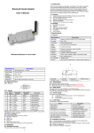
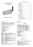
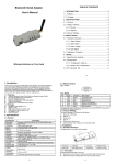
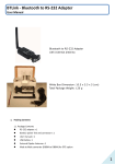
User Manual V1.4
Date: 2009.04.30
Bluetooth RS-232 adapter user manual
1. Packing contents
1.1 Contents:
z
RS-232 adapter x 1
z
Battery power line and connector x 1 (10 cm)
z
User manual x 1
z
USB Cable x 1 (1.5 m)
1.2 Pictures:
White box dimension: 13 x 10 x 6 (cm)
(Red: “+” , Black: “-“)
(Open the box)
(USB Cable)
(Battery cable & Connector)
2. Quick Guide
2.1 Plug the mini USB connector into the Bluetooth RS-232 adapter and connected with the
power adapter with USB or PC
2.2 Turn on the power from the slide switch. The red power LED is on.
Slide Power S/W
External Battery
Mini USB
Red LED: Power
Reset button hole
Blue LED: BT Status
2.3 Generally use the CTS/RTS side
CTS/RTS
(Default)
2.4 Please make sure the RS-232 setting on both sides are the same.
z Baud rate: 19200 bps
z Data bit: 8
1
User Manual V1.4
Date: 2009.04.30
z Parity: none
z Stop bit: 1
z Flow control: H/W or none
If not, please modify the setting by using hyper terminal software and the setup
command via COM port. The setup command shows on the section 11.
2.5 Two RS-232 adapter connections (Please refer to the section 3): One is master and the
other is slave. The slave is default setting and the master will be modified by the Setup
command, please check the section 11.
2.6 If you use the PC or NB, please start the IVT software or the built in Bluetooth
management software, like Toshiba.
3. Connection scenarios
3.1 Built in Bluetooth and RS-232 adapter
Remote site: (Serial Port)
1. Controller
2. Sensor
3. POS
4. Receipt printer
5. RFID
6. Card reader
7. LED Display
8. etc..
Built-in Bluetooth module
3.2 USB Bluetooth dongle and RS-232 adapter
Remote site: (Serial Port)
1. Controller
2. Sensor
3. POS
4. Receipt printer
5. RFID
6. Card reader
7. LED Display
8. etc..
External Bluetooth USB Dongle
3.3 Two RS-232 adapters: One is master and the other one is slave (default), The PC or NB
equipped with RS-232 connector.
Remote site: (Serial Port)
1. Controller
2. Sensor
3. POS
4. Receipt printer
5. RFID
6. Card reader
7. LED Display
8. etc..
With RS-232 Connector
3.4 Two RS-232 adapters: without RS-232 but with USB connector
Remote site: (Serial Port)
1. Controller
2. Sensor
3. POS
4. Receipt printer
5. RFID
6. Card reader
7. LED Display
8. etc..
USB to RS-232
Cable
With USB Connector
2
User Manual V1.4
Date: 2009.04.30
3.5 Two RS-232 adapters for micro controller.
Remote site: (Serial Port)
1. Controller
2. Sensor
3. POS
4. Receipt printer
5. RFID
6. Card reader
7. LED Display
8. etc..
Controller with RS-232
3.6 Handheld terminal with SPP profile
Remote site: (Serial Port)
1. Controller
2. Sensor
3. POS
4. Receipt printer
5. RFID
6. Card reader
7. LED Display
8. etc..
Handheld Terminal with
Bluetooth SPP profile
4. How to use external battery
4.1 Options: (The cable with connector : Red: “+” , Black: “-“)
z Standard A, AA or AAA battery: 3 units for each model.
z
Note:
1. If you use the rechargeable battery, the mini USB cable could be used to charge
the battery.
2. If the battery is not rechargeable, please don’t plug the mini USB. It will cause the
damage to the adapter and the batteries. It will be beyond the warranty.
3. Regard with the cable and connector for the battery connection, please check the
appendix 2.
Rechargeable Li-Polymer Battery: 3.3~3.7 VDC. The capacity is depend on the
applications. Generally working power consumption: 100 mAh (for reference)
Note: Please use the rechargeable Li-Polymer Battery.
4.2 Example:
Note: Please check the section 2.2, the “-“ pole is near the power S/W.
3
User Manual V1.4
Date: 2009.04.30
5. Factory Settings for COM port and Bluetooth:
z
Baud rate: 19200 bps
z
Data bit: 8
z
Parity: none
z
Stop bit: 1
z
Flow control: H/W or none
z
Bluetooth PIN code is "1234"
Bluetooth default setting: Please refer to Setup command sets table in the section 11.
6. Reset Button
6.1 Disconnect and reconnect a wireless connection (after a short press).
6.2 Restore the factory settings (after over three seconds' press).
7. Slide Switch
The slide switch can swap TXD/RXD and CTS/RTS signals.
By switching, you can set the adaptor either as a DTE (towards antenna connector) or a DCE
(towards RS232 connector).
8. Power Supply: The adaptor can be powered via the following source.
8.1 USB cable
8.2 External Battery: Please refer to section 4.
9. LED Status:
Status
Description
Power LED off
No power supply.
Power LED on
Firmware is running OK.
Link LED off
No pairing established.
Link LED fast (0.1 sec) blinking
Pairing (slave or master mode).
Discoverable and waiting for a
Link LED fast (0.3 sec) blinking
connection (slave mode).
Link LED slow (0.9 sec) blinking
Inquiring (master mode).
Link LED very slow (1.2 sec) blinking Connecting (master mode).
Link LED steadily on
Connection established.
10. Configuration the parameters of the COM port
10.1 Configure via Hyper terminal or Telnet
10.2 Use 3rd Party COM port tools: PuTTYtel, Hypertrm, Terminal, Virtual Serial Ports Driver XP
or etc…
11. Setup Command set (Please type in all capital letter)
Command
ADDRESS=
Value
?
AT
AUTO=
Description
This command is used to display the Bluetooth address of
the local adaptor.
Inquire the Bluetooth address of the local adaptor.
Check the connection status between control terminal and
the RS-232 adapter. Response: “OK” when the connection
is ok. Response: “ERROR” when the connection is not ok.
This command is used to enable/disable auto-connection
4
User Manual V1.4
(Default)
Date: 2009.04.30
Y
N
?
BAUD=
(Default)
BIT=
(Default)
1200
2400
4800
9600
19200
38400
57600
115200
?
8
?
CONNECT=
DEVICE
1~8
DEFAULT=
Y
DEVICE=
xxxx-xx-xxxxxx
R
I
DISCOVER=
N
feature. It is available only when the adaptor is in the master
role.
Automatically connect the adaptor to a device specified by
"DEVICE" or any available device if
"DEVICE=xxxxxxxxxxxx" is not executed.
Disable auto-connection feature. After it is executed, you
need to execute "CONNECT" to manually connect a remote
device.
Inquire the current setting.
This command is used to specify the baud rate of COM port.
1200 bps
2400 bps
4800 bps
9600 bps
19200 bps
38400 bps
57600 bps
115200 bps
Inquire the current baud rate.
Setup the data bit of the COM port
8 data bit
Inquire the current data bit.
This command is used to establish a connection. It is
available only when the adaptor is in the master role.
Connect the adaptor to a specified Bluetooth device.
It is available only when "DEVICE=xxxxxxxxxxxx" is
executed.
Connect the adaptor to a Bluetooth device in the
neighborhood found through "SEARCH=?"
This command is used to restore the default settings and
originate a warm start.
Restore the default settings (e.g. 19200 bps).
For security purpose, this command is used to specify a
unique remote Bluetooth serial adaptor to be connected.
In the master role, the adaptor pairs and connects with the
designated remote slave address. If the adaptor is in the
slave mode, this command is a filter condition to accept the
inquiry of the master device.
"xxxx-xx-xxxxxx" is a string of 12 hexadecimal digits.
Restore the status in which the adaptor can connect with
any remote address.
Inquiry the designated address that can be paired and
connected.
This command is used to specify whether the adaptor can
be discovered or connected by remote devices.
The adaptor enters the undiscoverable mode. If a pair has
been made, the original connection can be resumed. But
5
User Manual V1.4
(Default)
Date: 2009.04.30
Y
?
ECHO=
N
(Default)
Y
?
FLOW=
(Default)
N
Y
?
NAME=
xxxxx
?
PARITY=
(Default)
N
O
E
?
PIN=
xxxxx
N
?
PROMPT=
(Default)
Y
N
?
ROLE=
M
other remote master device cannot discover this adaptor.
The adaptor enters the discoverable mode.
Inquire the current setting.
This command is used to specify whether the adaptor
echoes characters received from the UART back to the
DTE/DCE.
Command characters received from the UART are not
echoed back to the DTE/DCE.
Command characters received from the UART are echoed
back to the DTE/DCE.
Inquire the current setting.
This command enable or disable flow control signals
(CTS/RTS) of the UART port. Note, the setting is not
affected by DEFAULT.
Disable flow control.
Enable flow control.
Inquire the current setting
This command is used to specify a name for the adaptor.
You can specify a friendly name using 0 to 9, A to Z, a to z,
space and –, which are all valid characters. Note that "first
space or -, last space or – isn’t permitted". The default name
is “Serial Adaptor”.
"xxxxx" is a character string with a maximal length of 16.
Inquire the name of the local adaptor.
This command is used to specify parity bit setting of COM
port.
None parity bit
Odd parity
Even parity
Inquire the current setting.
This command is used to specify a PIN. The default PIN is
"1234". Paired adaptors should have a same PIN.
"xxxxx" is a 4~8-digit string.
Cancel authentication by PIN.
Inquire the current PIN.
The command is used to decide whether result messages
are prompted when Setup commands are executed. The
result messages are: OK/ERROR for command execution,
or CONNECT/DISCONNECT for connection status.
Prompt result messages.
Not prompt result messages.
Inquire the current setting.
This command is used to specify whether the adaptor is in
the master or slave role. If the device role is changed, the
adaptor will reboot and all paired addresses will be cleared.
Set the adaptor to the master role.
6
User Manual V1.4
(Default)
Date: 2009.04.30
S
?
SEARCH=
?
STOP=
(Default)
1
2
?
VERSION=
?
Set the adaptor to the slave role.
Inquire the current role of the adaptor.
This command is used to search for any Bluetooth device in
the neighborhood within one minute. If any device is found,
its name and address will be listed. The search ends with a
message "Inquiry ends. xx device(s) found."
This command is available only when the adaptor is in the
master role.
Inquire Bluetooth devices in the neighborhood, listing 8
devices the maximum
This command is used to specify one or two stop bits of
COM port.
One stop bit.
Two stop bits.
Inquire the current setting.
This command is used to inquiry the firmware version.
Inquire the version codes.
Appendix 1: Specifications:
Specification
Baud Rate
Coverage
Connection
Signal
RS-232 Interface
Standard
Profiles
Data Bit
Frequency
Hopping
Modulation
Tx. Power
Rx. Sensitivity
Antenna
Antenna Gain
Power Supply
Description
Supports 1.2/2.4/4.8/9.6/19.2/38.4/57.6/115.2 Kbps
Up to 100 m
Point-to-point (pico net)
TxD, RxD, GND, CTS/RTS and DSR/DTR
D_SUB 9-pin female
Bluetooth specification version 2.0+EDR
Serial Port Profile(SPP)
8 bit
2.400 to 2.4835 GHz
1,600/sec, 1MHz channel space
GFSK-1 Mbps, DQPSK-2 Mbps, and 8-DPSK-3 Mbps
Max. 18 dBm (Class 1)
-86 dBm typical
Chip antenna (Default), SMA or Dipole (optional)
Chip antenna max. 1 to 2 dBi
+5 to +6 V DC
Current Consumption
Max. 90 mA
Operation
-20°C to +75°C
External Battery Input
3~5 VDC input
3.3 VDC Rechargeable Li-Polymer Battery or AAA x 3
Dimensions
35 mm (W) x 45 mm (H) x 15 mm (D)
7
User Manual V1.4
Date: 2009.04.30
Appendix 2: External Battery Connector Specification
1. Figures:
(Red: “+” , Black: “-“)
2. Electric Specification:
z Pitch Between Poles: 1.25 mm
z Current Rating: 1A AC/DC
z Voltage Ration: 100V AC/DC
z Contact Resistance: 20mΩ Max.
z Withstand Voltage: 500V AC/Minute
z Insulation Resistance: 100MΩ Min.
z Temperature Range: -25℃ To +85℃
Appendix 3: RS232 Interface
1. Pin-out:
2 Signals:
Pin
Signal
1
CD
DTE Direction
Input
DCE Direction
Description
Output
Not connected
Input
2
TxD
Output
Transmitted data
Output
3
RxD
Input
Received data
Output
4
DSR
Input
Not connected
N/A
5
GND
N/A
Signal ground
Input
6
DTR
Output
Not connected
Output
7
CTS
Input
Clear to send (Remarks)
8
RTS
Output
Input
Request to send (Remarks)
Input
9
Vcc
Input
Power supply
Remarks: The default hardware configuration is for using CTS/RTS. The DSR/DTR is rarely
used.
Declaration:
1. The information contained in this document is subject to change without notice.
2. Document Release V1.4, Date: 2009.04.30
8