1
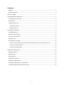
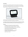
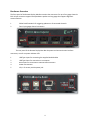
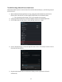
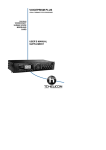
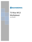
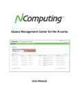
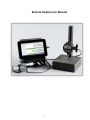
Remote Display User Manual 1 Contents Features .................................................................................................................................................... 3 Hardware Overview .................................................................................................................................. 4 Quickstart Guide ........................................................................................................................................... 5 Android Application Operation ..................................................................................................................... 6 Launching and Connecting ........................................................................................................................ 6 Main Display.............................................................................................................................................. 7 Configuring Channels ................................................................................................................................ 7 Quadrature Devices .............................................................................................................................. 8 Digimatic Devices .................................................................................................................................. 9 External Data Connection ............................................................................................................................. 9 PC USB Connection ................................................................................................................................... 9 RS-232 Serial Connection ........................................................................................................................ 12 Communication Protocol ........................................................................................................................ 12 Parameter List ......................................................................................................................................... 13 File Transfer from Tablet......................................................................................................................... 14 Transfer via SD Card (microSD cards can be purchased from you local computer store) .................. 14 Transfer via USB Connection............................................................................................................... 16 Transfer to Cloud Storage ................................................................................................................... 16 Supplemental Information .......................................................................................................................... 18 Digimatic Interface .................................................................................................................................. 18 Signal Timing ........................................................................................................................................... 18 Data Ordering.......................................................................................................................................... 19 Digimatic Data Format ............................................................................................................................ 20 Quadrature Signal Format ...................................................................................................................... 21 Installing Unsigned Drivers in Windows 8 .............................................................................................. 22 Troubleshooting Android Connection Issues .......................................................................................... 27 2 Introduction The Remote Display is a richly-featured measurement system that allows for the simultaneous connection of up to four gauges and displays their current measurements on a connected Android tablet. In addition, the Remote Display can connect to up to two external data consumers (desktop computer, laptop, PLC, or any generic serial device) over RS-232 and USB. The Remote Display has been designed to work with nearly any gauge that outputs data in Digimatic format. In addition, device that output raw quadrature can be used as well. As a standalone measurement system, the Remote Display provides a very intuitive and user-friendly way to configure and monitor several gauges at once. Connecting the Remote Display to a computer or other serial device makes data collection and statistical process control (SPC) simple and easy. Features Simultaneous connection of up to four measurement instruments Both Digimatic or raw quadrature devices supported on all four ports Nearly any Digimatic gauge – regardless of manufacturer – supported. User-friendly and intuitive Android application for easy process monitoring. Global footswitch makes triggering data updates easy External USB and RS-232 connections facilitate simple SPC Wide supply voltage range (9V to 24V) USB power can be used instead of an external AC adapter High quality, low profile enclosure and tablet stand Bright LED power indication 3 Hardware Overview The front panel of the Remote Display Mux Box contains the connectors for up to four gauge channels. Each 10-pin connector supports both quadrature probes and any gauge that supports Digimatic communications. 1 Global send footswitch for triggering updates on all connected channels. 2 Four 10-pin gauge channel connectors The rear panel of the Remote Display Mux Box the power and communication interface connectors, as well as a power indicator LED. 1 USB Type A port for connecting the supplied Android tablet 2 3 4 5 USB Type B port for connection to a computer RS-232 port for connection to external data consumers Power LED indicator 12V, 1.5A center-positive power jack 4 Quickstart Guide The following instructions will demonstrate how to operate the Remote Display with one Digimatic indicator and one quadrature Probe. 1. Plug in the supplied power adapter to the Remote Display Mux Box (item 5 on page 3). The red LED on the rear panel will light up. 2. Power up the supplied Android tablet. Press and hold the On Button (approx. 5 seconds) until HP logo appears on screen and then release the On button. The display will take approx. 30 seconds to startup. Using the supplied USB Micro to USB Type-A cable (item 1 page 3 on Back Panel), connect the Android tablet to the Remote Display Mux Box. Do not connect the tablet to the USB Type-B connector, as this will not function properly! 3. The Remote Display application should automatically start on the Android tablet. If it does not start, unplug the tablet from the gauge, wait a few seconds, and then reconnect. 4. Plug a quadrature probe into channel 1 a. The Android application defaults all channels to quadrature mode, so the gauge should start reporting counts immediately after connecting. Confirm this by moving the spindle of the probe. 5. Plug the device (with Digimatic output) into channel 2 To configure channel 2 for Digimatic communication mode, long-press on the CH 02. Channel 2 Properties page will appear on tablet. S oll do to the setti g fo Gage T pe, the ake su e Digimatic is selected. Press the back button on the tablet to return to the main display. 6. Fo all Digi ati de i es, data a e a uall e uested p essi g the Re uest utto fo the associated channel. Alternatively, data can be automatically updated at constant intervals using the automatic update feature. To set an automatic update interval ( the Remote Display will not update the Digimatic Data unless requested): a. Long-press on the appropriate channel (CH 01, CH 02, CH 03, or CH 04) b. Scroll down to the optio titled Auto- e uest i te al c. Select the desired update rate ( fastest rates may not be supported by all devices) Note that the Re uest utto ill o lo ge e isi le fo that ha el. It is ot possi le to manually request while the automatic function is active. 5 Android Application Operation Launching and Connecting The Remote Display Android application will automatically launch and connect when the tablet is connected to the Remote Display Mux Box. Alternatively, the app can be launched by clicking on the Remote Display icon from the App Drawer. After connecting the Android tablet to the Remote Display Mux Box and launching the app, the system will establish communication. The connection status text at the top-left corner the application will read Remote Display as see elo . If the de i e sho s a status of Dis o e ted o E o , e su e that the Re ote Displa is po e ed using the external AC adaptor and that the Android tablet is connected to the USB-A plug on the back of the display. Refer to Hardware Overview section for more information about identifying the connectors. 6 Main Display The main screen of the Remote Display application is shown below. As channels are enabled and disabled, the screen will update dynamically to maximize the amount of screen area available. This example shows two con e ted de i es ha els is a Quad atu e QUAD i st u e t a d ha el is a Digi ati DIGI i st u e t. If Digi ati is hose as Gage T pe a d o device is connected to that channel, then TIMEOUT will appear on the display. The primary features of the main screen are illustrated in the list below. 1. Clear Button (quadrature devices only) – Press and Hold the Clear Button to zero the displayed measurement for that channel. 2. Hold Button (quadrature devices only) – Press Hold to toggle on or off hold function. To enable /disable Hold function and configure (min, max, or freeze) go to Channel Properties page. 3. Log Data Button – Press to record current measurement 4. Request Button (Digimatic devices only) – Press to request reading from selected channel 5. Clear All Button – Press to zero all quadrature channels 6. Request All Button – Press to request reading from all Digimatic channels 7. Log All Button – Press to record current measurement for all channels Configuring Channels Regardless of the connected gauge type, all channels have a set of common settings. To access the settings for a given channel, swipe from the left side of the screen towards the center of the tablet (alternatively, press the a k utto o the ta let’s soft ke e u , a d the li k o the a e of the appropriate channel. 7 Regardless of the type of connected device (Quadrature or Digimatic) there are several settings that are always available. These settings are summarized in the following list: Setting Channel Enabled Gage Type Unit Type Mode Absolute Offset Travel Direction Tolerance High Tolerance Low Tolerance Ratio Mode Ratio Value Automatic Log Log Interval (s) Show Analog Scale Analog Scale Show Leading Zero Notes Enables/Disables channel. Disabling a channel will hide it from the main display. Selects the channel function between Quadrature and Digimatic modes. Selects measurement unit between Inch, Millimeter, and Hidden Selects indication mode between Incremental (default), Absolute, and Total Indicated Runout (TIR). TIR is only available for Quadrature Devices Entry of absolute offset (ABS mode only) Selects between forward and reverse travel direction. Enables/Disables tolerance mode. If this mode is enabled, the analog indication for this channel will turn red when the measurement falls outside of the specified bounds. Sets the maximum allowable tolerance value for this channel. Sets the maximum allowable tolerance value for this channel. E a li g Ratio ode ill s ale the u e t alue the alue of the Ratio Value setti g. Scale multiplier for current gage measurement. Enables automatic data logging on an interval Sets the logging interval if Automatic Log is enabled Enables display of the analog scale in addition to the readout value Selects the maximum value to display on the analog scale readout. Enables/Disables leading zeros on current measurement. Quadrature Devices By default, channels are set up in quadrature mode, which provides a real-time display of the current i di ato ’s easu e e t. The following settings are only available for quadrature channels: Setting Hold Hold Mode Notes Turns on/off hold mode for this chancel. This setting can be accessed by p essi g the Hold button for the current channel on the main screen. If Hold is enabled, this setting selects between the available hold modes: Min, Max, and Freeze Set the Encoder Resolution of the device fo e a ple . 5 o . Encoder Resolution Encoder Unit Type Selects the unit type of the encoder glass scale (Metric or Imperial) Sets the display resolution of the remote display Resolution Enables display of min and max readings in addition to the readout value Show Min/Max 8 Digimatic Devices Channels can also be set up to read output from Digimatic devices. These devices need to be polled for their current data. The following settings are only available for Digimatic channels: Setting Log on Request Auto Request Request Interval (s) Notes If enabled, a timestamped entry will be made to the data log every time the data is refreshed manually Enables/Disables automatic data refresh. Sets the data update interval if Auto Request is enabled. External Data Connection The remote display supports data connections over both USB and RS-232 communications. PC USB Connection The device may work with older operating systems but only Windows 7 and 8 are supported by the manufacturer. When connecting the Remote Display to a host computer over USB, the Remote Display will function as a Virtual COM Port (VCP), which emulates a standard RS-232 serial connection. To use this feature, follow these steps to establish communication between the display and the host PC (these instructions assume that host computer is running Windows 7): 1. Install the USB drivers that were bundled with the Remote Display. Be sure to install the correct drivers for the version of Windows (32-bit or 64-bit) that you are installing on. This can be determined by opening the System properties (Control Panel -> System and Security -> System) and checking the System Type field. 2. Power the Remote Display Mux Box using the supplied AC adapter. The red LED on the rear panel will light up to indicate the device has turned on. 3. Connect the Remote Display Mux Box to the host computer by plugging a USB cable between the USB Type B connector on the rear panel of the Remote Display and a USB port on the host computer (this cable can be purchased at your local computer store). 4. If the drivers have been installed correctly, Windows will recognize the Remote Display and will show a notification that the device has been connected. Now that the PC USB has been properly established, the VCP can be opened either by data logging software or manually through a terminal client. Most terminal clients that support standard serial communications will be compatible with the Remote Display. One free application, PuTTY, is the recommended application to use with the Remote Display. You can download it using the following link http://www.chiark.greenend.org.uk/~sgtatham/putty/ 9 To install PuTTY, follow this procedure: 1. Once on the Putty we site s oll do to “ite ap a d li k o Download PuTTY! 2. Scroll down to Windows Installer for everything except PuTTYtel click on Installer: putty-0.63installer.exe. 3. When the installer finished downloading, double-click on it to start. Follow the prompts to complete the installation. To open the VCP and query the Remote Display for the current gauge reading on channel one, follow these steps. This guide will assume the user is using PuTTY to make the connection. 1. Open the terminal client and u de Co e tio t pe he k the i le a ked “e ial . 2. Enter the COM po t u e i the “e ial Li e o . If this is ot k o , it a e fou d i the Device Manager: a. Open the Start menu (or press the Windows key on the keyboard) b. T pe De i e Ma age a d the p ess e te c. E pa d Po ts COM & LPT d. The Remote Displa ill appea as Vi tual COM Po t CDC COM he e is the port number. 10 3. Click on Connection -> Serial on the left sidebar, and make sure the connection parameters are set as shown below (Enter COM Port number if different from COM1) 4. Cli k Ope to o e t to the Re ote Displa . A su essful o e tio ill ope a la k terminal window. 5. To test the o e tio , p ess the E te ke . The essage No su h o a d! should appea on the screen. If nothing is displayed on the terminal screen, disconnect the device, cycle power, and then repeat this procedure. 6. Refer to the Communication Protocol section below for a list of available commands. 11 RS-232 Serial Connection The Remote Display supports an RS-232 connection to data consumers, such as a computer or PLC. To connect the Remote Display to an external RS-232 device, use the following procedure: 1. Find the female RS-232 connector on the rear panel of the Remote Display Mux Box. 2. Using a shielded RS-232 cable, connect the Mux Box to the external data consumer. a. Depending on the device and cable configuration, it may be necessary to use a femaleto-male gender changer. They can be used freely without any impact on the Remote Display functionality. 3. Use the following RS-232 settings on the external device to establish communication with the Remote Display Mux Box. 9600 8 1 None XON/XOFF Speed (baud) Data Bits Stop Bits Parity Flow Control 4. Refer to the Communication Protocol section below for a list of available commands. Many modern computers use USB ports in lieu of RS-232 ports. The Remote Display can still communicate to these devices over RS-232 by using a Serial-to-USB converter. There are many such devices available. When searching, ensure that the device is compatible with the Operating System version that is being used on the computer. Communication Protocol The following list summarizes the serial commands available for exchanging data with the Remote Display Mux Box. These commands apply to both the RS-232 and PC USB communication modes. Type e te or return afte o a d. Command A N:A D N:D R N:R C N:C rstErr N:pXXX=? N:pXXX=<new value> Save help Description Print current gauge readings for all channels P i t cu e t gauge eadi g fo Cha el N . ex: 1:A for channel 1 Print data packet* for all channels P i t data packet* fo cha el N Request a measurement update on all Digimatic channels on Tablet Re uest a easu e e t update fo cha el N on Tablet Clear gauge measurements for all channels (quadrature only) Clea gauge easu e e t fo cha el N (quadrature only) Resets global errors Get the alue of co figu atio pa a ete XXX fo cha el N “et the alue of pa a ete XXX fo cha el N to < e alue> Saves any modified parameters to retentive flash Show help text and command list * Data Packet format: Channel:Reading:Analog Scale:New Data:Max:Min Note that the Analog Scale field has a maximum value of 1000Note N = channel number 12 Parameter List The following list summarizes the configuration parameters available for configuring each device channel. When editing these values over RS-232 and/or USB, make sure to call the Save command to commit the values. Otherwise, they will be reset if the Remote Display is powered down. Important Note: While these parameters can be changed over RS-232 and USB, the preferred way to edit these settings is by using the Channel Settings menu on the Android application. While the Android tablet is connected to the Remote Display, writing to these parameters will be blocked (reading is still allowed). If parameter writing over the external data connection is required, the Android tablet must be disconnected first. Parameter p003 Description Channel Enabled p004 Units p005 Measurement Mode p006 Travel Direction p007 Hold Enabled p008 Hold Mode p009 Tolerance Enable p910 Upper Tolerance p911 Lower Tolerance p914 Absolute Offset p016 Gage Type p017 Glass Type (encoders only) Base Multiplier (one encoder tick) p018 p019 Ratio Mode Enabled p020 Ratio Multiplier 13 Values 0 – No 1 – Yes 1 – Inches 2 – Millimeters 3 – Hidden 0 – Absolute (ABS) 1 – Total Indicated Runout (TIR) 2 – Incremental (INCR) 0 – Normal 1 – Reverse 0 – Disabled 1 – Enabled 0 – Freeze 1 – Min 2 – Max 0 – Disabled 1 – Enabled Enter value without decimal Ex: 012345 = 0.12345 Enter value without decimal Ex: 012345 = 0.12345 Enter value without decimal Ex: 012345 = 0.12345 0 – Digimatic 1 – Encoder 1 – Inches 2 – Millimeters 5– . 5 10 – . 100 – 0.001mm 200 – 0.002mm 0 – Disabled 1 – Enabled Enter value without decimal p921 Analog Scale p023 Gage Resolution p024 Leading Zero Ex: 012345 = 0.12345 Enter value without decimal Ex: 012345 = 0.12345 1– . o . 2– . 5 o . 3– . o . 4– . 5 o . 0 – Disabled 1 – Enabled File Transfer from Tablet There are three common ways to transfer stored data (.csv files) to other devices: transferring via the microSD card; transfer via USB connection; and transfer using email. Transfer via SD Card (microSD cards can be purchased from you local computer store) Files can be saved to the external microSD Card and transferred to any PC with a microSD card reader. To copy logging data to the card from within the Remote Display Android application, swipe right from the left side of the screen (or press the back button) to show the appli atio e u, a d li k Vie Data Logs. 14 F o this s ee , li k the Cop to “D utto . The appli atio data to a folder on the external microSD card. Remove the card from the slot on the tablet (locatio sho to access the files. 15 ill auto ati all t a sfe the loggi g elo a d o e it to the PC’s a d eade Transfer via USB Connection Files can be copied directly from the tablet to a PC over USB. To do this, connect the tablet to a PC over USB and wait for Windows to install the driver for the tablet. Once the drivers are installed successfully, open a new Explorer window and navigate to My Computer. The tablet should appear under the list of drives and devices, as shown below. The data logs for the Remote Display application will be found in the following location: Internal Storage\Logs Transfer to Cloud Storage If the tablet is connected to the internet over WiFi, data logs can be sent directly to cloud storage services like Google Drive, SkyDrive, and DropBox. To do this, go to the Remote Display application and return to the View Data Logs screen as shown previously. Click the Edit button and choose the channel number of the data log that you want to transfer. 16 This will open the Spreadsheet application. Click “a e As o the top heade if this is ot displa ed, li k o the “ utto i the top left side of the appli atio to sho it , a d the li k o Cloud “to age at the top of the dialog o . Find the preferred cloud storage service and follow the instructions to save the logs. 17 Supplemental Information Digimatic Interface The following describes the standard 10-pin Digimatic connector pinout. Signal Timing Figure 1-1 shows a timing chart for the case where the host device triggers a data transfer by asserting the active-low request signal (/REQ). The gauge then sends data (the DATA signal) that is clocked by the CK line. In this case, the data ready (RDY) line is not applicable. Figure 1-2 shows a timing chart for the case where the gauge asserts its active-low data ready signal (/RDY) to indicate that a new gauge measurement is available. This triggers a data transfer that is initiated by the host device. 18 Data Ordering 19 Digimatic Data Format 20 Quadrature Signal Format The following diagram and schematic describe the format of quadrature data that the Remote Display is expecting to receive. Failure to meet these specifications will not guarantee proper functionality of quadrature devices. Expected Quadrature Signal Quadrature Conditioning Circuit The following circuit is used internally in the Remote Display to condition the quadrature signals for decoding. Ensure that any quadrature devices connected to the Remote Display are compatible with the electrical specifications of this circuit. 21 Installing Unsigned Drivers in Windows 8 Users of Windows 8 or Windows 8.1 may experience difficulty installing unsigned drivers. The following procedure can be used to install these drivers . 1. From the desktop, move the cursor to the right side of the screen to show the Charms menu. Cli k o “etti gs. 22 2. Cli k o Cha ge PC “etti gs at the otto 3. “ele t Update & e o e fo to ope the o t ol pa el. the list of optio s 23 4. “ele t Re o e f o the esulti g the Advanced Startup heading. 5. F o this e u, li k o e u a d the T ou leshoot 24 li k o the Resta t o utto u de 6. “ele t Ad a ed Optio s f o the Troubleshoot menu 7. “ele t “ta tup “etti gs 25 8. O the e t s ee , li k Resta t to e oot the PC i e o e ode. O e the o pute e oots, the follo i g e u ill e sho . P ess F7 o the ke oa d to sele t Disa le d i e sig atu e e fo e e t 9. When Windows loads, it will not look different than usual, but it will be possible to install unsigned drivers. Follow the typical driver installation process to install the drivers. Be sure to reboot the computer normally immediately after installing the drivers. 26 Troubleshooting Android Connection Issues If the Android tablet reports a communication Error with the Remote Display, try the following steps to resolve the issue: 1. With the Remote Display application running, unplug the Android tablet from the Remote Display. Wait a few seconds, and then plug the tablet back into the Remote Display. a. If the connection status sho s E o still, p o eed to the e t step. 2. Unplug the Android tablet from the Remote Display, and exit the Android application. 3. On the ta let, ope the app d a e , lau h “etti gs, a d li k o Apps. 4. Cli k o Re ote Displa to sho the App i fo s ee . Cli k o the popup warning window. Fo e “top a d li k OK o 5. Plug the Android tablet back into the Remote Display, and the application will launch automatically. 27