1
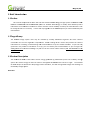
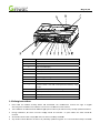
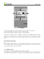
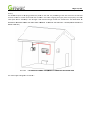
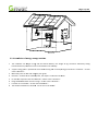
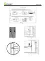
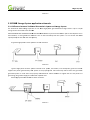
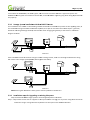
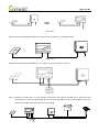
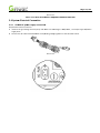
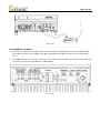
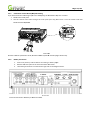
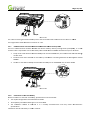
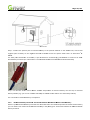
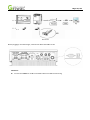
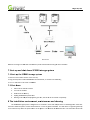
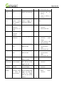
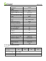
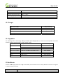
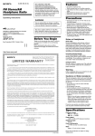
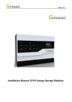
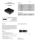
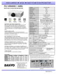
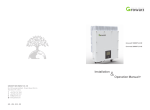
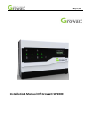
Page P 1/45 Instaallation n Manual Off Grow watt SP2000 Page P 2/45 list 1 Brief Intrroduction ............................................................................................................................. 4 4 1.1Prefaace ......................................................... .............................................................. ....................................... 4 4 1.2Targeet Group ................................................ .............................................................. ....................................... 4 4 1.3Product Description ..................................... .............................................................. ....................................... 4 4 ns ...................................... .............................................................. ....................................... 5 5 1.4 Safeety Instruction 2 Safety ............................................................................................................................................... 6 2.1 Purp pose Use ................................................ .............................................................. ....................................... 6 6 2.2 Safeety Measure ........................................... .............................................................. ....................................... 6 6 2.3 Sym mbols introducction on the SSP2000 unit . .............................................................. ....................................... 7 7 3 Product Description n ......................................................................................................................... 8 8 3.1 Grow watt SP2000 .......................................... .............................................................. ....................................... 8 8 3.2 Labeel Explanation n ........................................ .............................................................. ....................................... 8 8 3.3 Size and weight ........................................... .............................................................. ....................................... 9 9 2000 storage solution ................................................ ..................................... 10 0 3.4 The advantage off Growatt SP2 4 Unpackin ng....................................................................................................................................... 10 0 5 Installatiion ..................................................................................................................................... 11 5.1 Basic installation requirementts .................. .............................................................. ..................................... 11 1 uctions .............................. .............................................................. ..................................... 12 2 5.2 Instaallation Instru 5.3 SP20000 energy sttorage solutio on and appliccation schematic .................................... ..................................... 16 6 5.4 System Electrical Connection ..................... . 9 .............................................................. ..................................... 19 unding ................................................... .............................................................. ..................................... 27 7 5.5 Grou 6 Commisssioning ............................................................................................................................... 28 8 6.1 Com mmissioning o of SP2000 sto orage system . .............................................................. ..................................... 28 8 6.2 Opeeration modess ........................................ .............................................................. ..................................... 28 8 6.3 LED AND LCD’S D DISPLAY .............................. .............................................................. ..................................... 30 0 4 6.4Communication............................................ .............................................................. ..................................... 34 7 Start‐up and shut down SP200 00 .................................................................................................... 36 7.1Startt‐up SP2000 ........................................... .............................................................. ..................................... 36 6 7.2 Shutt down ................................................... .............................................................. ..................................... 36 6 8 Attention n of the insstallation en nvironmentt, maintena ance and cle eaning ....................................... 36 9 Fault rem moval .................................................................................................................................. 37 10 Manufaacturer Warrranty ............................................................................................................... 39 9 11 Decomm missioning ........................................................................................................................ 41 11.1 Dissmantling SP2 2000 .................................. .............................................................. ..................................... 41 1 11.2 Paccking SP2000 0 ......................................... .............................................................. ..................................... 41 1 11.3 Sto oring SP2000 .......................................... .............................................................. ..................................... 41 1 11.4 Dissposing of SP2 2000 .................................. .............................................................. ..................................... 41 1 12 Productt specificaation ................................................................................................................ 42 12.1 Gro owatt SP2000 0 specification .................. .............................................................. ..................................... 42 2 12.2 DC C input termin nal parameter ................... .............................................................. ..................................... 43 3 12.3 Torrque ....................................................... .............................................................. ..................................... 44 4 12.4 Appendix ................................................... .............................................................. ..................................... 44 4 Page P 3/45 13 Certificaate ..................................................................................................................................... 44 4 14 Contactt ......................................................................................................................................... 45 Page P 4/45 1 Brief In ntroductio on 1.1Prefacce This manual will p provide the u users who usse the Growatt SP2000 en nergy storagee system of G GROWATT NEW W GY CO.LTD.SH HENZHEN (Shhort for Grow watt New En nergy as beloow) with detailed product ENERGY TECHNOLOG uctions. Plea se read this manual careffully and keeep the manua al where it caan informattion and instaallation instru be easilyy referred to if necessary. If there aree any upgrad des to the SP2 2000 System you will be n notified by th he manufaccturer. 1.2Targett Group The SP22000 storage system must only be installed by suitably acccredited eng ineers who have relevant certificattion for the local regulattion requirem ments. Carefu ul reading off this manuaal will provide the relevant informattion for installing, troubleshooting andd communicaations set‐up for Growatt SP 2000. Iff you have an ny question ns in the proccess of installation or set up, you can contact your local distribbutor or you can login intto www.gro owatt.com an nd email messsage. Or youu can call our 24‐hour serrvice hotline (+86 755‐29 9467281 & +4 44 7580‐0755‐155) 1.3Producct Descrip ption The Grow watt SP 2000 0 is used to store s excess energy gene erated by pho otovoltaic pa nels into a battery b storagge system. TThe excess energy can then be called on through tthe SP2000 a and the inverrter at night. The Growaatt SP 2000 adopts the cconversion off topology inn both directiions, and will manage botth charge an nd discharge of the batteery storage syystem. Overview: Page P 5/45 Po osition Description D A Tap on the m marked area B LCD display sscreen C LED of statuss display D DC output E panel input F DC switch G Secondary grrounding term minal H AC socket I The reservedd antenna hole J Current sennsor and NTC C sensor(Lead‐acid batterry only) socket K LAN cable soocket(for cable es monitoring) L RS232 port ccover M battery connnection point N BMS RS485 ccommunicatio on cable socke et(Lithium batttery only) 1.4 Safetyy Instructiions 1. Pease reead this man nual carefully before thee installation n. The manu ufacturer res erves the right to negatte warrantyy if the installlation has nott been carrie d out in acco ordance to thiis manual. 2. The instaallation of thee Growatt SP 2000 storagee system musst only be carrried out by s uitably qualiffied installerss. 3. During installation, no n covers orr outer casinngs should be removed ‐ ‐ no parts w within the un nits should be b touched. must comply w with the local electrical saffety standard ds. 4. All electrrical works m 5. Any elecctrical work m must be carried out by a ssuitably qualiified engineer. It is recom mmended thatt you establissh Page P 6/45 with your insstaller any ongoing service e and supportt arrangemen nts for any wo ork carried ouut. 6. Any equipment supplied to the grid should be registered to o the local grid should be rregistered witth. odules are beeing installed or worked w with in dayligght, the panels should be covered or isolated due tto 7. If PV mo risk from DC voltage geneeration. 2 Safety 2.1 Purpo ose Use The systeem chart of SSP2000 storagge solution: Chart 1.1 As sshown abovee, a standard complete griid‐connected d PV storage ssystem consissts of PV modules, SP2000, battery, PV inverter, utility grid and a other co mponents. When includ ding or retroofitting the SP2000 Storagge no other coree componentss are requiredd. System n Attention: The SP2000 Storage sysstem uses Lithium or Leead‐acid battteries to store DC electrricity from the PV panells. he installation environment should havve ventilation, and should d ideally be aat the temperrature range in Therefore, th between 0‐440 degree C with tempe erature contrrol, moisture range of 5% %‐85%. The installation environmenttal conditions sh hould be at leeast IP20. 2.2 Safetyy Measure e Risk o of high voltagge! R Relevant operration only byy professionaal personnel K Keep children n, disabled aw way from the storage syste em Page P 7/45 Risk off burns due to o hot enclosu ure parts! SSome parts of the enclosure e may becomee hot during o operation. Do not touch anyy parts other tthan the front lid du uring operatio on. SP20000 may emit slight amount of electromaagnetic wave d during operattion! Don’t stay a long tim me within the range of 20cm m from the SP P2000 storage e unit. Grounding Please ensure grou unding connecction of SP20000 is reliable tto make sure personal safetty. 2.3 Symbols introd duction on n the SP20000 unit symb bol description Dan ngerous voltagge! Risk of burns! Point of connecttion for ground ding protectio on Dire ect Current(D DC) Alte ernating Curreent(AC) The e SP2000 storaage unit comp plies with the requirementss of the app plicable CE gu idelines Page P 8/45 3 Producct Descrip ption 3.1 Growaatt SP 200 00 storage e unit Display an nd labels of SP2000 0 Unit Mark Description D Tap symbol Explanaation Tap to operate T e SP2000 unit (Detailed in ssection 6) Green light on G n Stattus symbol of SP2000 Red light on R Red R blinking b 3.2 Produ uct Label EExplanatio on Label contain ns the followiing informatio on: SP2000 running normally, ng chargingg or dischargin fault statte lig ght 1.Alarm state 2.Softwaare updating Page P 9/45 Description o of label: Prod duct Model Growatt SP20000 Input voltage range e 10 00‐580Vdc Max input power range of SP20000 30 000‐6000W Max input current 30A Max ccharge and disscharge poweer 2000W Discharge voltage rrange at nightt 15 50‐500Vdc Max charge and d discharge current of 10A 00 SP200 Battery voltage ran nge 46‐58Vdc 4 Max charge and d discharge current of ≤45A battery Lead acid battery or lithium Suitab ble battery typ pes battery Recom mmended batttery capacity range 90‐200Ah 9 Lead b battery50%DO OD The d discharge deptth control of bbattery Lithium battery80%D DOD Discharge capacity at night 2‐9kWh Safetyy certification CE LED status displayy Displaay LCD info ormation dispplay Degreee of protectio on IP20 Comm munication typ pe RS232/LLAN/WIFI(chooice) 3.3 Size and weightt Chart 3.1 A(mm) B(mm) C(mm) weeight(kg) Page P 10/45 5 Grow watt SP 2000 482 355 166 12 3.4 The ad dvantagess of Grow watt SP20000 storage e system Features belo ow: mple addition n to existing P PV system witth standard sttring inverterr Sim Batttery manageement system m, To satisfy ppattern of Leaad battery and lithium batt ttery Wide working vvoltage range:100V~580V V。 n。 Eassy installation Maax efficiency 9 94%。 Wireless or cabled monitorin ng via Interneet. 4 Unpackking Please checkk whether extternal packagging has any ddamage beforre unpacking At the pointt of unpackin ng the system, please chheck for anyy damage or missing parrts. This musst be reporteed immediately to the suppliier. ories are folloows: Growatt SP20000 unit partts and accesso A B C D E Chart 4.1 Item m Number Description A 1 Growatt SP20 000 unit B 1 User Manual C 1 electric curre ent sensor (Sta andard wire leength 5m) D 1 Battery temp perature senso or(Standard w wire length 1.5m/ only for lead‐acid battery)) E 4 M6 Setscrew F 1 Paper board(installation gu uide) F Page P 11/45 5 5 Installaation 5.1 Basic installatio on require ements A The installaation location n must be suitable for thee SP2000(and d the lithium battery packk)’s weight forr a long perio od time n must be suitable for the dimension of the SP2000 storage systeem(SP2000 u unit + battery) B The installaation location C Do not insttall the units on structuress constructedd of flammable materials D Do not insttall the SP200 00 storage sysstem near flaammable matterial. E The (Ingresss protection)) rate is IP20 which meanss the unit can n only be insta alled indoorss. F The batteryy unit should be installed cclose to the CController unit. G The humid dity of the installation location should bbe 0 ~ 95% HThe ambien nt temperature should be within ‐25℃ ℃ ~40 ℃ I The SP20000 Storage Un nit can be in nstalled in veertical or lean ning back po osition, but nnot leaning forward f or flat position. Pleaase refer to the below Chart 5.1 on and easy aaccess to the SP2000 unit, please refer r to the diagra am J In order tto ensure opttimal operatio below for tthe installatio on: Page P 12/45 5 Chart 5.2 00 unit near ttelevision anttenna or any other antenn nas and antennna cables K Do not insttall the SP200 L Do not install the system m in a living area – roof sppaces and garages are idea al. m is out of the e reach of chi ldren or non‐‐competent a adults. M Ensure thaat the system 000 storage system CAN NNOT BE INSTALLED NEAR FLAMMA ABLE MATER RIAL. Impropeer PLEASE NOTTE: The SP20 installation o or broken cable may cause arc whichh may cause serious fire if there is fl ammable ma aterial nearb by. Growatt will assume no lliability for any loss causeed by improp per installatio on or failure to observe tthe installatio on manual. 5.2 Installation Insttructions Note: Before installlation, pleasee first confirm m if it is an eexisting grid‐cconnected PV V system or aa totally new installation. If it’s a new insstallation, pleease install and commissioon the grid‐cconnected invverter first, thhen follow th he steps belo ow to integrate tthe Storage p plus system in nto the PV syystem. 5.2.1 Instaallation Layyout The installation plan for in nstalling the SSP2000 Systeem in a prope erty is as follo ows: n the mai ns entry to the t propertyy.(The red linne in the diagram below is The SP 20000 needs to be installed near current senso or line, The w wire length is 5m(no moree than 15m),Installation position nee ds to conside er distance less Page P 13/45 5 than it) AC plug pointt for AC poweer to the unitt. The positio oning of the uunit must also consider th he The SP2000 requires an A nect a curren nt sensor from m the controoller unit to tthe outgoing AC supply frrom the prop perty. The RJ4 45 need to conn cable (with ssensor attach hed) is 5m in n length. Thee maximum length l should d not exceedd 25m. YOU MAY NEED TO T PROVIDE A N NETWORK CA ABLE AND RJ45 CABLE CO OUPLER TO EXTEND E THE LENGTH IF TTHE REQUIRED DISTANCE IS MORE THAN 5M.) Chart 5 5.3 * AN AC C SUPPLY SOCCKET IS REQU UIRED TO POW WER UP THE SP2000 UNIT T m is as follow ws : The whole syystem diagram Page P 14/45 5 Chart 5.4 5.2.2 Instaallation of e energy storrage machin ne w 12 kgg, and the Liithium Battery unit weighs 45 kg. Thherefore suffficiently stron ng 1. The conttroller unit weighs locationss must be pro ovided in order to attach tthe units verttically. 2. A paper fixing guide is provided tto assist withh locating the e necessary ffixing points ffor the contrroller.(As th he chart 5.55a below) 3. Mark fou ur points on tthe wall usingg the plan gu ide. 4. Drill fourr Ф8 holes aat the marked d points, the depth is a miinimum of 55 5mm. 5. Fix the fo our expansion bolts intoФ Ф8 holes(Ass the chart 5.5b below) 6. Hang thee SP2000 unitt on the four fixings(As tthe chart 5.5cc below) 7. Lock the nut of setscrrew(As the chart 5.5d beelow) ole installation has finished d(As the ch art 5.5e belo ow) 8. The who Page P 15/45 5 a) b) c) d) e) Page P 16/45 5 Chart 5.5 5.3SP20000 Storage e System a application n schematic 5.3.1 Differrence between Traditio onal Photovvoltaic Systtem and Sto orage Syste m The Growattt SP 2000 sto orage system m is for use w with single‐ph hase grid‐con nnected strinng inverters. Up to 3 equ ual strings can be connected to the SP 200 00. M IS NOT DESIGNED FOR M MULTI‐TRACKKING INPUTS.. If you have dual MPPTs (this is where e panels are in THIS SYSTEM odd numberrs, or facing different dire ections such as East and West) then the option iis to use one e of the MPP PT inputs(usuallly the one witth the most p panels). wn as below: A typicaal single‐phasse inverter sysstem is show Chart 5.6 els, PV invertter, load andd power grid d. The inverteer Typical single‐phasee inverter sysstem consistss of PV pane ar panels to the propertyy load. Extra electricity w will be fed to the grid wheen supplies the power generated by sola mand is higheer than the PV panels are generated power is morre than the property loaad demands. Where dem generating, tthe grid will supply the additional requuired load. PV Storaage System w with SP2000 is shown as b elow: Chart 5.7 Page P 17/45 5 In the above the SP2000 u unit, the batttery pack, andd the sensor have been ad dded to a typpical PV system. The Battery pack are installed on the DC sidde, and the SSP2000 is regiistering any ppower being e exported from m SP2000 and B the propertyy. 5.3.2 Storrage System m installatio on with Duaal‐MPPT invverter If an installattion uses a Du ual or Twin trracking invertter because tthe installatio on has panelss on two oppo osing roofs, o or the installatio on strings have different n number of paanels, then yo ou can use on ne of the 2 M MPPT inputs – – generally whichever haas the greateest generation n, and leave tthe other string(s) going directly to thee inverter. Insstallation diagram as b below: Chart 5.8 If the installaation wishes tto use both strings of a Duual Tracking inverter, then n as in the diaagram below each string will need its own storage system(SP20 000, battery ppack and senssor). Chart 5.9 Notice: During the in nstallations above, please note the possition of the ssensors. 5.3.3 Insttallation ste eps for Upgrading an eexisting PV ssystem Steps to o add the SP2 2000 storage system to ann existing PV ssystem are ass follow: Step 1: Fullyy isolate the DC and AC supplies to thhe system be efore carrying g out any woork. Using MC4 connecto ors atttach the string or strings frrom the PV ppanels into the inputs on the SP2000 Coontroller. Page P 18/45 5 Chart 5.10 Step 2: Connect the outpu ut of SP2000 to the input of your PV in nverter, as the diagram sh ow: Chart 5.11 Step3: Conneect the battery to SP2000,, you can refeer to 5.4.7 for connection of battery. Chart 5.12 mp the curren nt sensor on the propertty inlet live line, l and con nnect the RJ445 end to th he RJ45 socket Step 4: clam marrked with CT sensor on th he SP2000, att the same time plug the e AC PLUG onn the SP2000 0 to electricitty, ntire system iis ready to w ork smoothlyy. and finally the en Page P 19/45 5 Chart 5.13 Please note: A AN AC PLUG PPOINT IS REQ QUIRED FOR T THE SP2000 U UNIT 5.4 System m Electriccal Connecction 5.4.1 SP22000 AC pow wer supply connection n Preparationss before connection: A measure the grid voltage and frequency and m make sure the e voltage is 22 20/230Vac , tthe frequencyy is 50/60Hz in single phase. with correspoonding safetyy regulation to the AC PLU UG section. B Connect the AC cable certificated w Chart 5.14 Page P 20/45 5 Chart 5.15 5.4.2 SP20000 PV Conn nection 1. Ensure th hat any cables are not insttalled with crrossed polaritty. Any reversse may causee unrecoverab ble damage. Ensure tthat the shorrt‐current (am mps) of the PV V strings do n not exceed th he max input current of th he Storage Plus. V connectionns. The conne ectors are installed in pa irs (male and d female). Th he 2. The diaggrams below show the PV connecttors for PV arrrays and inve erters are staandard MC4. Chart 5.16 Page P 21/45 5 Chart 5.17 ws the maxim mum input cu rrents: 3. The tablee below show Type M Max PV input ccurrent Growatt SP 2000 30A Max output currrent to invert rter 30A 2 * Reco ommended ccable size ≥4 4mm /12 AW WG 5.4.3 Conneection of Te emperature e sensor forr Lead‐acid battery 1. Please co onfirm your battery type before conneection. For in nstallations using Lead‐aciid battery, yo ou will need tto use the temp perature senssor. Lithium b battery has B MS system to o communica ate with the SSP2000 unit, all the runnin ng data will be acquired thrrough the communicationn, so temperrature sensorr is not need ed, but a ne etwork cable is onnect the SP P2000 unit to lithium batteery. needed to co 2. Remove the cover plaate at the terrminal beforee connection.. Chart 5.18 Page P 22/45 5 As pictured above, with the cover pllate removedd, take the white w 2PIN fe emale plug oof the batteryy temperature nsert it into thhe 2PIN male plug marked d with NTC/SEENSOR. sensor through the cover plate, and in 1.5m in lengthh) specificatio ons: UL1332 26 AWG TS 2200℃ 300V. Remark: teemperature sensor wire (1 nnection of cu urrent sensorr 5.4.4 Con NTC/SENSOR,, If you are using lead‐acid battery, booth temperatu ure sensor an nd There are 2 ssockets at thee section of N current senso or need to bee plugged in. but for Lithiuum battery, only current se ensor needs tto be conneccted. Chart 5.19 Install the temperature seensor for lead d‐acid batteryy as the diagrram above. on Current senssor connectio The SP22000 installattion requires a current sennsor to be clamped on th he live line off the incomin ng property A AC supply. The ccurrent senso or should be p plugged in thee socket show wn below, Chart 5.20 Remark: The RJ45 sensor cable is 5m iin length (onee end with 8P P modular plug, the otherr connected w with sensor). If Page P 23/45 5 this length iss not sufficieent an extenssion can be uused as show wn below up p to a maxim mum of 25m. This is show wn below: Chart 5.21 MPORTANT TO O INSTALL THE E AC SENSOR R CORRECTLY. Please see th he diagram beelow: IT IS VERY IM Chart 5.22 As illustrated above, open the sen nsor and clam mp on the live e line of the A AC supply cabble with the a arrow pointin ng towards the Grid and awaay from the p property. Thenn close and secure the sen nsor to compplete the fittin ng. Page P 24/45 5 5.4.5 Con nnection of Hard Wired (LA AN) Monitorring o monitor thee storage systtem via cablee (LAN), the in nstallation ste eps are as fol low: If you wish to 1. Rem move the coveer plate. 2. Use the second access hole through the cover plate (Lan line), and a insert it into the soccket under th he AN/RS485. labeeled words LA 23 Chart 5.2 N line specification: RJ45, sstandard LAN N line (with 8P P modular plu ug at both ennds). Remark: LAN 5.4.6 Batttery Connection 1. Ensure the polarity is co orrect before connecting to battery inp put. onnection. 2. Remove thee cover plate at the termi nal before co 3. The batteryy connection is located onn the right side as the diagram below: Chart 5.24 hown as beloow: Electrical cconnection off battery is sh Page P 25/45 5 CChart 5.25 The cable connecting the Lithium Batttery Pack to t he Controllerr needs to be e sized at leasst 8mm2 or AW WG8. hould be a maximum of 1 .5m. The length off this cable sh 5.4.7 Com mmunication connection b between SP22000 and Lith hium battery’’s BMS There are co ommunication between SP2000 S and lithium batte ery’s battery managemennt system(BM MS), so a RJ4 45 network cable is required d to connect tthe battery too the COM so ocket of SP200 00. Installatioon steps are a as follow: he distance be etween Batteery Pack and the SP2000 u unit, the netw work cable ha as RJ45 fittinggs 1. Firsttly confirm th on b both ends. 2. Ensu ure the LED status indicato or on the batttery is OFF b before connecting betweeen the Batteryy Pack and th he SP20000. 3. Conn nect to the Liithium Batterry Pack and innto the COM port on the S SP2000 unit aas shown belo ow. CChart 5.26 nnection to Le ead‐acid Batttery 5.4.8 Con Before conneection to the lead‐acid batttery, please cconfirm the items below: 1. The outp put voltage off the lead‐aciid batteries iss 48V. 2. Total Cap pacity of lead d‐acid batteryy is no less th an 80AH. 3. The insttallation cab binet of lead d‐acid is in a suitably ventilated area a and fuully meets manufacturer m rs’ specificaations. Installation o of lead‐acid battery is show wn as follow: Page P 26/45 5 CChart 5.27 nect the positive pole of lead‐acid baattery to the positive term minal on thee SP2000 unit, connect th he Step 1. Conn 2 negative pole of battery to the nega ative terminaal of SP2000. Ensure the power cablee used is at least 8mm or o AWG8. nd convenien nce to mainttain, A pair oof Anderson connectors(e e.g. KST BMCC2S or same kind of otheer For safety an brand battery connectorss) or a DC isolator is recom mmended bettween the SP2 2000 and lea d‐acid batterry. Step 2. Fix tthe NTC senssor used to detect d ambieent temperatture of lead‐acid battery onto the to op of lead‐accid battery cabin net. (e.g. you can use a do ouble‐sided taape to adhere e the NTC sen nsor onto thee battery cabiinet). The connectiion of lead‐accid battery is completed. ommendatorry connection n: Connectioon Between SSP2000 and D Darfon Lithium m Battery 5.4.9 Reco Darfon is quaalified lithium m battery manufacturer off Growatt. Ass to the detailed operationn of Darfon LLithium battery you can referr to user man nual of Darfon n lithium batttery in the paacking box. Connection beetween SP 20 000 and Darfo on battery as follow: Page P 27/45 5 1. Firsttly insure the’’ status’ LED indicator of liithium batterry is in the exxtinguished sttatus. 2. Prep pare to conneect the DC po ower cables and commun nication cable e between litthium batterry and SP2000, 2 the ssectional areea of the DC p power cable should be at least 8mm , you are advvised to use the KST BMC2 2S conn nector, which h is within th he battery paacking box, to connect th he battery. Thhe communication cable is standard straightt through RJ45 network caable crimped with RJ45 mo odular plugs. nection of terminals is sho own as below w: 3. Conn CChart 5.28 After alll connection ns done, gently press thee ‘wake up’ KEY of the lithium l batteery. While th he ‘status’ LEED indicatorr turns green, the battery starts workinng. 5.5 Groun nding PV Array Grrounding The frame an nd mounting racks of PV p panels shouldd be firmly and securely co onnected to gground. DC Groundiing SP2000 storagge system can n be used in both groundingg system and floating syste em. If it is usedd in groundingg PV system(P PV positive or neegative connected to groun nd), there musst be a galvan nic isolation transformer insstalled between inverter an nd utility grid. Grounding Device ed in the PV ssystem, the in nverter output If the positivee pole or thee negative pole of the PV aarray needs to be grounde should be inssulated by an n Isolation Tra ansformer. Connection aas below: Page P 28/45 5 L PV V array Transform me r In verte r Griid N P E CChart 5.29 6 Commiissioning 6.1 Comm missioningg of Energyy storage machine ngs into the SP2000’s inp puts. Keep th he 1. Cheeck the polarrity of PV strring inputs, tthen connectt the PV strin buillt‐in DC switcch in OFF position. 2. Con nnect the battery b to th he SP2000 unit. Make sure the NTC N sensor(ffor lead‐acid d battery) or o com mmunication cable(for lith hium battery)) is well and ccorrectly conn nected. 3. Plugg the SP2000 0 unit to an AC C supply. 4. Theen the SP2000 unit will be e turned on and enter standby mode. If there is eelectricity power over thaan 1000W flowing in n from the grid, the SP20000 unit will en nter discharging mode in 11 minute.(If there is no loaad in tthe property at that mom ment, it’s reccommended to turn on a home appli ances over than t 100W fo or seveeral minutes to check if th he SP2000 ca n go into disccharging) 5. Cheeck the polarrity and volta age on SP20000 output, th he voltage sh hould be arouund 450VDC in dischargin ng mod de. 6. Unp plug the SP20 000 unit, con nnect the outtputs of SP20 000 to the in nverter(positiive to positivve, negative tto neggative). 7. Plugg again, if theere is electriccity power gr eater than 10 00W flowing into the propperty, the SP P2000 will staart disccharging and the inverterr will be firedd up and con nnect to the grid in 1 miinute. SP2000’s LCD would scro oll the state information. LLED area wouuld display th he current sta ate. 8. Turn on the builtt‐in DC switch, the whole system will sstart working. 6.2 Operaation mod des 6.2.1 Normal charge mode When there is good PV geeneration, the SP2000 Stoorage system will work in ccharge Modee. he DC voltagee is above 150 0V and the SPP2000 unit has detected p power being exported to the grid, it w will ● When th send anyy residual electricity to the e battery storrage. ● When th he DC voltagee is less than 130V, The ennergy storage e machine will leave the ccharge mode e automaticallly and retu urn to standbyy mode until the PV voltagge increases. ● When th he PV voltagee is greater than 150V, annd the curren nt sensor didn’t detect eleectricity flow wing out to th he grid, the SP2000 unit doesn’t charrge battery annd remains in n standby mo ode. Page P 29/45 5 CTED TO AN A AC POWER SOURCE FOR IT TO WORK. NOTICE: SP2000 MUSST BE CONNEC 6.2.2 Normal discharrge mode When the PV V generation is low or stop pped, then thhe system will operate norrmal dischargge mode. ● When D DC input volttage is less than t 100V a nd SP2000 unit u has dete ected demannd from the property, th he controlleer will supplyy energy from m the batteriees to the inve erter, which w will in turn suupply the pro operty. the LEED indicatorr will show co onstant green n light. ● When DC C voltage is leess than 100V V but there iss no detectio on of demand d from the prroperty, the sstorage system will remaain in stand‐b by mode. ● When PV V voltage is greater than 1 120V, the SP22000 unit willl exit discharg ge state and rreturn to standby mode. NOTICE: Must connecct to AC, or th he energy stoorage system won’t start u up. 6.2.3 Faullt mode The SP2000’’s intelligent control systtem will connstantly mon nitor and adjjust the systtem status, if any fault is detected in tthe system th he LCD displayy will show thhe fault information. The fault light willl illuminate. NOTICE: ormation plea ase refer to 9..1 a)For detailed fault info ult informatio on is in relatio on to the inveerter side issu ues causing the Storage Syystem to be u unable to b)Some fau function. 6.2.4 Shuttdown mod de The SP2000 u unit will be in n working sta atus all the tim me if plugged d to AC supply. If you needd to shut dow wn the SP200 00 unit, just unp plug the AC p power cable. NOTICE: ated any suppply from the panels. Always switcch off the DC Switch to be certain you hhave disconnected or isola Page P 30/45 5 6.3 LED A AND LCD’SS DISPLAY 6.3.1 LED display are ea Chart 6.2 location A B C D E F description PV panel power Batteriess of the Storagge system The Prop perty PV invertter Grid Pow wer Power directional flow w 6.3.2 Each h status’ LED light indication scheematic State one: Beefore sunrise, the battery is empty andd the property demands electricity eneergy. The pow wer is supplied d from the Grid d: Chart 6.3 State two: A After sunrise the PV output starts incrreasing, the p power will be e first used tto supply the e property an nd offset the deemand. The insufficient part will be suupplied by grrid. As the PV V output goees up, the ele ectricity poweer from the grid d will becomee less and lesss. Page P 31/45 5 State three: with the sunlight getting sstronger and stronger, the e PV panels w will generate eexcess power to charge th he 2000 starts chharging at the e moment, th he battery apartt from the paart being used to offset thhe local demaand, The SP2 energy flow iss illustrated ass follow: Chart 6.4 with the sunlight being mo ore stronger, the PV output will be gre eater than prroperty load plus maximum State four: w charging pow wer of SP2000 0(2kW) , the rresidual poweer will be fed tto the grid, po ower flow is shhow as follow w: Chart 6.5 Chart 6.6 Batt ery is fully ch harged he same situaation as state e two, with ti me going by, the power o of the photovvoltaic panelss is not enouggh State five: Th to satisfy thee property loaad ever due to insufficientt sunlight, the en the powerr grid would ssupply the shortage part. Page P 32/45 5 Chart 6.7 hen the sun goes out com mpletely, thee photovoltaicc panel will not n generatee power, Whe en SP2000 haas State six: wh detected elecctricity beingg supplied from grid, it wil l start discharging to satisffy the properrty’s load, Chart 6.8 hen the outpu ut of SP2000 cannot satissfy the property demand ddue to insuffficient capacity State seven: At night, wh he shortage part will be supplied from tthe grid, in battery, th Chart 6.9 6.3.3 LCD display collumn LCD display ccolumn is useed to show th he current staatus, basic information an nd fault infor mation. The correspondin ng information w will be scrolleed in turn on LCD display w when the SP2 2000 is powe ered up. Page P 33/45 5 Chart 6.10 locatio on A B C de escription The ccurrent SP20000 Status Vario ous performannce informatio on Statu us indication liight ons for line A:: Display optio 1、 Standby state: The machine is in standby state,, no chargingg or dischargin ng. 2、 Chargingg state: The generated PV power is cha rging the battteries. 3、 Dischargging state:Th he batteries a are discharginng power to tthe inverter. 4、 Warningg state: The m machine is sho owing warninng, this does n not affect the e normal ope ration of the system. 5、 Fault state :The SP2 2000 unit hass detected a ffault, and sto opped operating. d. 6、 Programming state:The SP2000 unit is being programmed The second line displays aas follow: ally, when ta pping on the e tap sign are ea, the displaays will chan nge in order as a In normal staatus, it scrolls automatica follows: operating: 1. Normal o Battery Info Vpv and Vac Ppv Pc harge Pd discharge Vbuckout Ec_todayy Ed__today PttoUser P PtoGrid BatteryInfo(change everry 5s) 2. When taapping on fron nt lid Vac Ppvv Pchargge Pdisccharge V Vbuckout Ec_today Ed_todaay BatteryInfo VpvandV d Vbus SN M Model FWVersion ComModee ComAd ddr PtoUserr PtoGrid SysttemTime BlueTooth_ _Zigbee_Wifi SetWind dow BatteryInfo 3. In the following pages, display will remain two minutes whe en double tap pping nfo/VpvandV Vac/Ppv/Pcharge/Pdischargge/Vbuckout//Ec_today/Ed d_today/PtoU User/PtoGrid/Vbus/SN/Mo BatteryIn del/FWV Version/ComM Mode/ComAd ddr/SystemTiime/BlueTootth_Zigbee_W Wifi 4. Under FFW Version paage,double tap, the Firm mware build vversion will ap ppear 5. In Set W Window page,double tap p will enter thhe setting inte erface: Set Wind dow knockk on twice continuously Input 123(finish enterin ng the passwoord, triple tap p)languagge Set ComAddr Set ComM Mode Set SystemTime e Set measuremen nt Accuracy of m Display valuees shown by tthis system are guideliness only. The daata is not calib brated to be accurate for purposes succh Page P 34/45 5 as billing. 6.4Comm munication n 6.4.1 Use the PlusBu us software to set up th he SP2000 storage con ntroller The PlusBus software can n be downloaded from dow wnload sectio on of Growattt official webbsite. onnect the SPP2000 to yourr laptop for th he parameterr check or mo odifying. The A USB to RS2232 cable is reequired to co 2‐bit DIP swittch adjacent to the RS232 2 port should be in OFF po osition for parrameter setti ng: The wiring diiagram is as ffollows: Chart 6.11 6.4.2 Mon nitoring thee SP2000 Sto orage Systeem The SP2000 ccan be monittored either b by a Wi‐Fi donngle or by a h hardwired solution. Both oof these solutions will work only with thee Growatt Shine Server software. Schemee A : Usee the Wi‐Fi dongle for wireless remotee monitoring. Page 35/45 5 Chart 6.12 Before pluggging in the WIFI dongle, set both bits off the DIP swittch to ON: Schemee B : Connect the SP2 2000 to route er via networrk cable for hardwired monitoring. Page P 36/45 5 Chart 6.13 NOTICE: the length of LAN N cable is deccided by userrs themselvess according to o actual situattion 7 Start‐up and shu ut down SP2000 sstorage syystem 7.1Start‐u up the SP2 2000 stora age system m 1. Switch on AC and DC isolator of the inverter; AC power cord d of SP2000 in nto the wall ssocket, it will start automa atically; 2. Plug the A he built‐in DC switch of SP2 2000. 3. Turn on th 7.2 Shut d down 1. 2. 3. 4. 5. Switch off DC an nd AC isolatorr Turn off the inveerter battery Discconnect the b Unp plug SP2000’ss AC power co ord Waiting until LED D,LCD displayy have gone oout, the SP wiill be shut down completeely 8 The insstallation environm ment, maaintenancce and cle eaning The SP22000 Storage System is dessigned to be installed in areas with tem mperatures oof 0‐40 degree es C. Particular attention sho ould be paid to locate the e installation in areas of go ood ventilatio on. This will aassist in regulating build u up to heat which may affect the performa ance of the sy system. The G Growatt SP 20 000 Controlleer unit functio ons without aan Page P 37/45 5 inbuilt fan, ttherefore go ood ventilatio on is requireed to assist with w cooling. The Lithium m Battery pa ack does havve integrated fans, although again good vventilation wiill assist in temperatures b being controllled. m fails due to temperature parameters, check the following pointts: If the storage system osition for th he Cheeck there arre no obstrucctions to airfflow around the units, choose an apppropriate po insstallation. using lead‐aciid batteries, ccheck if the N NTC sensor is fitted correcttly. If u Cheeck whether the battery ttemperature is within the operational rrange. 9 Fault Fiinding All products are fully testeed and certified before leaaving the manufacturing ffacility. If youu are having d difficulties witth on please conntact you disttributor, or lo og on to ww ww.growatt.co om, where yo ou planning or ccarrying out an installatio can check thee Q&A prograam. If a fault occu urs with yourr SP2000 Energy storage syystem, please e inform Grow watt and be pprepared to p provide relateed information iin order to asssist with fault deduction. Our professional aftersale es service peersonnel will a assist you. mation that w will be needed will be as foollows: Typical inform Serial numbeer Model Fault informaation on LCD Brief descripttion of probleems The battery vvoltage The dc input voltage Can you retell the failure problem? If yyou can, whatt kind of a sittuation Did the problem happen iin the past? Solar panels model and PV array configguration ease also proovide If you are usiing lead‐acid batteries, ple ufacturer and d model. Battery manu The total outtput voltage o of the batteries How long havve the batterries been worrking since coommissioningg. 9.1 System m fault info ormation lisst and troub bleshootingg suggestion ns LCD display Fault description Fa ault When Error: 100 Firmware version Firrmware mismatch mismatch Error: 101 Communiccation fault SP P Sttatus version Faault M3 cannot receive Faault ata from DSP da Sug ggestion Upd date FW w with right verssion 1. Check communicattion cable Page P 38/45 5 2. Restart Sola r Plus BMS COM Communiccation fault Fault Co ommunicatio n failure Faault be etween M3 annd BMS 1. Check 4855 cable between SSP and battery 2. Check if bbattery is sleeping BMS Error: BMS failu ure and BM MS failuree and Faault neither either chargge and xxx charge ne harge is disscharge is alloowed and disch allowed Dep pend on BM MS error code Error: 116 Over current Ovver‐current protection triggered by Trip Zone Faault 1. Check PVV input terminals 2. Restart Sola r Plus Error: 117 Over current Ovver‐current protected by software Faault 1. Restart Sola r Plus Error: 118 Over BUS‐voltage BU US voltage higgh protection Faault 1. Check battery terminals when charge 2. Check dum mmy load when dischaarge Error: 119 Communiccation fault DSSP cannot receive Faault da ata from M3 1. Check communicattion cable 2. Restart Sola r Plus Error: 119 Communiccation fault DSSP cannot receive Faault da ata from M3 3. Check communicattion cable 4. Restart Sola r Plus PV Voltage PV Voltagee High High PV V voltage highher than Faault 58 80V for 100m ms Che eck PV input vvoltage PV PV input PV V voltage low wer than Faault uited 20 0V and PV current Short‐circuit short‐circu higgher than 5A A Battery reversed Battery teerminals PV V voltage low wer than Faault reversed ‐10V for 100mss PV Access PV input and Wrong discharge output of Solarr Plus misconneccted V voltage low wer than Faault PV 20 0V and BUCKK voltage higgher than 550V and cannot be dragged own by 30s dummy do loa ad on 1. Check PVV terminals 1. Check terminals input battery 1. Check PV innput and BUCK output terminals Page P 39/45 5 PV Reversed PV teerminals PV V voltage check Faault reversed siggnal is high er than 2.5 57V Che eck PV terminnals L‐N Reversed AC teerminals Th he voltage bbetween Faault reversed N and Earth higher than 100V for 1100ms Che eck AC terminnals No AC AC voltagee low AC C voltage low wer than Faault 50 0V Che eck AC voltagee NTC Open NTC open NT TC open Che eck NTC term inals Fuse Open Fuse Open n Vd drop on fusee higher Faault than 10V for 2000ms Battery Open Battery terminal t attery voltage Faault Ba open (on nly for sampled by SPP is 10V lithium batttery) wer or highher than low BM MS MPPT Trouble MPPT Trou uble SS Timeout Soft start run out Bu us or BUCK voltage Faault cannot get target of time min soft value after 2m sta art Faault Exxit discharge for no Faault MPPT five timees Che eck fuse Che eck battery teerminal Che eck state inverter of PV Che eck voltage s ample of BUS or BUCKK BMS Error: BMS failu ure and BM MS failure annd either Warning W either chaarge or ch harge or disccharge is xxx discharge is alllowed allowed Dep pend on BM MS error code Bat voltage Battery low low Che eck battery teerminals voltage Ba attery voltagge lower Warning W than 44V for 1000ms Bat T Battery ure out Outrange temperatu of specifieed range for charrge or discharge attery tempperature Warning W Ba ou ut of specifieed range for chargee or is disscharge(rangge settable) Che eck battery temperaturee No AC No AC pow wer flow Po ower flow bbetween Warning W grid and use r lower power flow than 50W for 10 minutes Che eck if AC current sensor is coonnected well 10 Manu ufacturer Warrantyy This certificaate representts a 5 year w warranty for tthe Growatt products listed below. Poossession of this certificatte validates a sttandard facto ory warranty of 5 years froom the date o of purchase. Warranted products Page P 40/45 5 This warrantyy is applicable solely to th he following pproducts: Growatt SP2000. Limited Pro oduct Warranty (Applicable u under normaal application, installation , use and service conditions)Growatt warrants the above listeed products to b be free from defects and//or failure sp ecified for a period not exxceeding fivee (5) years fro om the date of sale as shown in the Proo of of Purchase e to the Origi nal purchaser. d in these “LLimited Warrranty” are exxclusive and are a expresslyy in lieu of and a exclude all a The warranties described ed, including g but not llimited to, warranties of o other warraanties, whether written,, oral, exprresser implie merchantabiility and of fittness for a pa articular purppose, use ,or application, a and all other r obligations o or liabilities o on GROWATT , u unless such o other obligati ons or liabilities are expressly agreed to it in writiing signed an nd the part of G approved byy GROWATT , GROWATT shall have nno responsibility or liabilitty whatsoeveer for damagge or injury to t persons or property, or fo or other loss or injury resuulting from aany cause whatsoever arissing out of orr related to th he hout limitation, any deffects in the modules orr from use or installatio on. Under no n modules, inccluding, with circumstancees shall GROW WATT be liable for incidenntal, consequential or special damagess howsoever caused; loss o of use, loss of p production, lloss of revenues are therrefore specifically and witthout limitatiion excluded d to the extent legally permiissible, GROW WATT ’s aggre egate liabilityy, if any, in daamages or otherwise, sha ll not exceed the invoice aas paid by the ccustomer. The “Limite ed Product Warranty” described abbove shall noot apply to, aand Growatt shall have noo obligation oof any kind whaatsoever with h respect to, a any machine which has be een subjected d to: Misuse, abuse, neglect or acccident; ation or appliccation; Altteration, imprroper installa modification o or attemptedd repairs; Unauthorized m e product; Inssufficient ventilation of the Traansport damaage; Breeaking of the original man nufacturers seeal; No on‐observancee of Growatt installation aand maintenaance instruction; Failure to obserrve the appliccable safety rregulations wer failure su urges, lightin ng, flood, fire,, exposure to o incorrect usse, negligencce, accident, fforce majeurre, Pow exp plosion, terro orist act, vandalism or daamage caused d by incorrecct installationn, modificatio on or extrem me weeather conditions or otherr circumstancces not reasonably attributable to Grow watt. The warranty shall also cease c to app ply if the prooduct cannot be correctlyy identified aas the product of Growattt. ber on the machines havee been altere ed, removed o or Warranty claaims will not be honored if the type off serial numb rendered illeegible. Liability The liability o of Growatt in n respect of a any defects inn its machines shall be lim mited to comppliance with tthe obligation ns as stated in these terms and conditio ons of warraanty. Maximu um liability shall be limiteed to the sale price of th he owatt shall acccept no liability for loss off profit, resultant of indire ect damage, aany loss of ellectrical poweer product. Gro and / or com mpensation off energy supp pliers within tthe express m meaning of that term. Page P 41/45 5 The warrantyy rights as meant m herein are not trannsferable or assignable to o any third pparty excepting the nameed warranty hollder. Warranty C Conditions If a device beecomes defeective during the agreed G Growatt facto ory warranty period and pprovided that it will not b be impossible or unreasonab ble, the devicce will be, as sselected by G Growatt: e center for rrepair; 1、 Shiipped to a Grrowatt service 2、 Repaired on‐site; nt device of eequivalent vallue according g to model annd age. 3、 Excchanged for aa replacemen over transporrtation costs in connectio on with the re eturn of defeective module es. The cost of The warrantyy shall not co the installation or reinstaallation of the modules shhall also be e expressly exccluded as aree all other related logisticcal and process costs incurreed by all parties in relationn to this warraanty claim. 11 Decom mmission ning 11.1 Dism mantling th he energyy storage 1. 2. Dissconnect the storage mach hine such as mentioned in n section 7。 Dissconnect the upper cable of the storag e machine watch out the SP’s shell heat and prrevent to scald d minutes until tthe SP coolingg and then to d disassembly! wait 20 m 3. 4. Unscrew all the connecting ccable diator and wall‐mountted’s anchor sscrew and the en take downn the machine e from wall Unscrew the rad 11.2 Packking the en nergy storrage mach hine Usually placeed energy sto orage machin ne in the packking box with h tape sealing g, If the energ rgy storage m machine canno ot reoccupy, Yo ou can choosee a cheap ca arton for pac kaging. Carto on requireme ents must meeet the size of o the inverteer port energy sttorage machiine overall weeight. and can supp 11.3 Storiing energyy storage machine Store the eneergy storage machine in a dry place w where ambient temperatu ures are alwa ys between ‐‐ 25°C and +600°C 11.4 Disposing of the energyy storage machine Do not dispose of energgy storage macchine togethe er with househ hold waste. Pleaase accordancce with the di sposal regulattions for electtronic waste whicch apply at the installation site at that tim me. Ensure th hat the old Page P 42/45 5 unit and, wheere applicablee, any accessories are dispo sed of in a pro oper manner 12 Produ uct speccification 12.1 Grow watt SP se eries energgy storagee machine e product specificattion M Model Speccification Growattt‐SP2000 PV array input a and output data: Inputt PV voltage e range 100V~580VDC Max input current from m PV arrayy 30 0A *1 Max power 20 000W Full load inpu ut DC vooltage rangee 200V~450VDC output voltage e range 150V~500VDC Rated outputt voltage((mpp voltaage for inverter) 380V Max current to SSP2000 10A 1 Rated output cu urrent 5.3A 5 Number of ind dependent MPP trackkers/strings per MPP trackker 1/3 1 Outp put strings from f SP20000 to inverrter 3 Batte ery data Batteery voltage range 44V~58VDC Max charging vo oltage 57VDC/58VDC*2 Max charging cu urrent ≤45A Max dischargingg current ≤45A Typee of battery Lead‐acid ba L attery/Lithi um batttery) Batteery capacityy 90~2 200AH Deep p of dischargge 50% DOD/80% DOD**3 Page P 43/45 5 dailyy nightt consumption electtricity Othe ers: 2~9 9KWH Maxiimum efficiency 94 4.0% Inputt grid voltagge range(ssingle phase) 230Vac±15% Operrating temp perature rannge: 0℃~ ~+40℃ Altitu ude 20 000m Cooliing conceptt Na atural Envirronmental Ratin ng Prote ction IP20 (in ndoor used)) Noisee emission (typical) ≤4 40dB Certificates and approvals: CE over voltage pro otection yes y Low voltage pro otection yes y over current pro otection yes y over load protecction yes y Outp put currrent proteection sshort yes y PV and battery reverse po larity proteection yes y (Five e years) Warrranty: Conn nection for P PV array sidde H4/M MC4(opt) Conn nection for b battery comm munication: Screw terminal RS232/LAN/WIFI(optt) display LED D+LCD Dimeensions(W/H/D) 520/3 340/160 Weigght 15kg 12.2 DC in nput term minal parameter H4 specification: Rated current ( (90 2.5mm2/14AW WG 4mm2/12 AWG 6mm2/10 AW WG 10mm m2/8AWG 32A 40 0A 44A 65A ℃ environm ment) Nominal system voltagge 600V DC(UL) 600V DC(TUV)) Contact rresistance 0.2 25mΩ(moddel) Protectio on grade IP6 68 Page P 44/45 5 Socket co ontact materiaals Co opper, tin Insulation materials Thermoplastics UL94 V‐0 Ambient temperature range ‐40 0℃ to +90℃ Wire stripping length 7.0 0mm(9/32) Cable cassing diameter 4.5 5 to 7.8mm(3//16: to 5/16”)) 12.3 Torq que Up pper cover screews 1.3N Nm(10.8 1bf.in n) Sheell and RS232screws 0.7N Nm(6.2 1bf.in) Dc connector 1.8N Nm(16.0 1bf.in n) M66 screwdriver 2N Nm(18 1bf.in) Gro ounding screw w 2N Nm(18 1bf.in) 12.4 Appeendix The following chart is th he energy sto orage machinne optional appendix a list, if there is aa need pleasse contact th he w Energy Tech hnology Co., LLtd or dealer orders. Growatt New naame desccription GRO OWATT P/N Sh hine Webbox Com mmunication ddata record MRR00.0001700 Sh hine Vision recceiver Rece eptor of Comm munication daata record MRR00.0000201 Sh hine Vision em mitter Laun nchers of Com mmunication d data record MRR00.0000601 Zigbee COM M interface 2000.0007000 W Wi‐Fi COM M interface MRR00.0001400 Bluetooth COM M interface MRR00.0002200 13 Certificate Growatt SP20000 apply within the scop pe of the worrld, So the invverter have to satisfy diffeerent countries and region ns of different ssafety standards mod del Growatt SP2000 e Certificate CE,SAA,RCM M Page P 45/45 5 14 Contaact If you have technical problems abou ut our produucts, contact the Growatt Service lin e or dealer. We need th he ormation in o order to provide you with the necessarry assistance: following info mber 1. Energy sttorage machine Serial num 2. Energy sttorage machine module in nformation 3. Energy sttorage machine communiication modee 4. Energy sttorage machine fault information codee 5. Energy sttorage machine Display co ontent 6. The man nufacturer and model of th he battery 7. Battery capacity and connection m mode w Energy Tech hnology Co.,LLtd Growatt New Building B, JJiayu Industriial Zone, 28 G Guangming Rooad, Longten ng Communityy, Shiyan, Baooan District, SShenzhen T: + 86 7555 2951 5888 8 F: + 86 7555 2747 2131 1 E: [email protected]