1
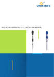
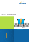
APOX sensor user manuAl
Cable includes guard
AP Sensor and
shield connections
LEMO plug
3
APOX sensor user manual
Copyright © 2010 · Unisense A/S
Version October 2010
APOX sensor user manual
Unisense A/S
TABLE OF CONTENTS
Congratulations with your new Product! . . . . . . . . . . . . . . . . . . . . . . . . . . . . . . 1
Support, ordering, and contact information
1
Overview . . . . . . . . . . . . . . . . . . . . . . . . . . . . . . . . . . . . . . . . . . . . . . . . . . . . . . . . . . . . . . . . . . . . 3
Getting started . . . . . . . . . . . . . . . . . . . . . . . . . . . . . . . . . . . . . . . . . . . . . . . . . . . . . . . . . . . . 4
Unpacking a new sensor
Test the oxygen sensing part Test the action potential unit 4
4
4
Measurements . . . . . . . . . . . . . . . . . . . . . . . . . . . . . . . . . . . . . . . . . . . . . . . . . . . . . . . . . . . . . . 6
Mounting the sensor
Electrical noise
6
6
Storage and maintenance . . . . . . . . . . . . . . . . . . . . . . . . . . . . . . . . . . . . . . . . . . . . . . . . 7
Cleaning the sensor
7
References . . . . . . . . . . . . . . . . . . . . . . . . . . . . . . . . . . . . . . . . . . . . . . . . . . . . . . . . . . . . . . . . . . 8
Warranty and liability . . . . . . . . . . . . . . . . . . . . . . . . . . . . . . . . . . . . . . . . . . . . . . . . . . . . 9
Repair or adjustment
9
Troubleshooting . . . . . . . . . . . . . . . . . . . . . . . . . . . . . . . . . . . . . . . . . . . . . . . . . . . . . . . . . 10
Congratulations with your new Product!
Support, ordering, and contact information
If you wish to order additional products or if you encounter any
problems and need scientific/technical assistance, please do not
hesitate to contact our sales and support team. We will respond to
your inquiry within one working day.
E-mail: [email protected]
Unisense A/S
Tueager 1
DK-8200 Aarhus N, Denmark
Tel: +45 8944 9500
Fax: +45 8944 9549
Further documentation and support is available at our website
www.unisense.com.
Replacement of sensors
Unisense will replace sensors that have been damaged during shipment provided that:
•
The sensors were tested immediately upon receipt in accordance with the delivery note
and the manual
•
The seal is still intact.
•
The sensors are returned to Unisense for inspection within two weeks.
•
The sensors are correctly packed for return to Unisense, in accordance with the note
included in the sensor box.
1
Recommended amplifiers
One-channel amplifier: OXY-Meter or Microsensor Monometer
Multi-channel amplifiers: Microsensor Multimeter or Microsensor
Multimeter - 4-channel Oxymeter
The action potential sensing part must be connected to an action
potential meter
Overview
The Unisense APOX microsensor is a miniaturized Clark-type
oxygen sensor combined with a platinum action potential
microsensor. The sensor is designed for research within
neurophysiology.
The Unisense oxygen microsensor is a miniaturized Clark-type
oxygen sensor with an internal reference and a guard cathode.
The action potential electrode consists of a platinum tip
protruding through a glass coating.
With its minute tip size, excellent response time, and insignificant
stirring sensitivity the APOX microsensor facilitates reliable and
fast measurements with a high spatial resolution.
AP Sensor and
shield connections
We recommend that the Unisense Oxygen
microsensor and the Unisense Redox
microelectrode manuals are consulted before
proceeding.
Warning
Unisense sensors
are neither
intended nor
approved for use
on humans
Cable includes guard
The signal from the oxygen sensing part of
the APOX sensor should be connected to a
high-precision picoammeter.
The action potential sensing part must be
connected to an action potential meter and a
reference electrode must be provided. In many
set-ups, this reference consists of the metal
support for the experimental subject.
NOTICE
For details on
working principle
consult oxygen
sensor manual and
redox electrode
manual
LEMO plug
2
3
8. The signal from the pre-amplifier should
Getting started
Unpacking a new sensor
When receiving a new microsensor remove the shock-absorbing
grey plastic net. Please do not remove the seal and protective
tube before the following steps are successfully completed.
Test the oxygen sensing part
Connect, test, and calibrate the oxygen sensing part as described
in the Unisense oxygen sensor manual.
be sent to a 2nd-stage amplifier and then a
device to view the signals.
WARNING
Do not remove
seal and protective
plastic tube before
the following steps
are successfully
completed.
9. The total amplification should be around
2000x (this may vary).
10. The signal should be filtered with a low
cut-off frequency of ~250 Hz and a high
cut-off frequency of ~8kHz..
11. Introduce high frequency voltage pulses
into the saline bath using two separate
electrodes connected to a function
generator (e.g. use Physiologic Instruments
Model# VCC600) Pulse duration should be
Test the action potential unit
1. Place the tip of the sensor into a saline bath
2. Put a reference electrode (e.g. silver-silver
chloride) into the saline bath and connect
it to a large metal object (e.g. a metal
stereo-tactic frame)
3. Connect the black AP wire on the APOX
sensor to the input of a pre-amplifier
4. The reference for the pre-amplifier should
be the same large metal object from 2)
~0.01 seconds or lower and it should repeat
about 10 times /second.
12. Vary the amplitude of the voltage pulse
until it is possible to distinguish the pulses
from the background noise. You should be
able to distinguish pulses below 100 mv.
As an alternative way to test for basic function, connect the AP
connection (black wire) and a separate reference electrode to
a millivoltmeter. Then, connect the shield connection to the
reference plug of the millivoltmeter and finally perform the
function test described in the Unisense Redox electrode manual.
5. Leave the blue wire disconnected
6. Connect the external ground of the
picoammeter (plug in the back) to the
reference of the pre-amplifier (the large
If the sensor functions according to the above procedure, the
seal and protective plastic tube can be carefully removed and
measurements can be started.
metal object)
7. Shield the connections between the
sensor and the pre-amplifier with tin foil
or another Faraday cage-like device and
connect this shield to the large metal object
from 2)
4
5
Measurements
Storage and maintenance
Mounting the sensor
Store the sensor in the protective plastic tube used for shipping.
The microsensor can be stored with the tip exposed to water or air.
The room in which the oxygen microsensor is stored should be dry
and not too hot (10-30°C). If the sensor is used regularly it can be
stored polarized.
Lateral movements of the microsensor and physical disturbance
of the microsensor equipment or table should be avoided as
they may cause the tip to break. Therefore measurements should
be performed only in a stabilized set-up. We recommend the
Unisense lab stand LS18 and the Unisense micromanipulator
MM-33 (MM33-2 double). The set-up should be placed on a sturdy
table free of moving or vibrating devices.
Electrical noise
Cleaning the sensor
The electrode can by cleaned by immersing it in nitric acid. Keep
the electrode in the nitric acid solution for about 30 minutes and
allow it to cool and rinse with water afterwards.
The oxygen and action potential sensor signals may be
affected by electrical noise in the environment and by physical
disturbances. Thus precautions should be taken to minimize such
effects. Electrical shielding in the form of a Faraday cage may be
necessary. As described in the Unisense Oxygen microsensor and
the Unisense Redox microelectrode manuals, the set-up must be
physically stable.
Connecting the sensor
Connect the AP connection (black wire) to a suitable amplifier. The
APOX sensor also has a shield connection, which can be connected
to a ground connection, the AP amplifier reference plug, or the
AP amplifier chassis to reduce electrical noise. However, electrical
noise is a complex phenomenon, and it is not certain that using
this connection will improve the measurements.
‘Local’ shielding of naked connections with e.g. aluminium foil
can be advantageous. The user will have to experiment with the
specific set-up to find the optimal use of shielding. When the
sensor is fully connected, the measurements can be performed.
6
7
References
Warranty and liability
• Masamoto, K.; Vazquez, A.; ang, P.; im, S.
Microsensors are consumable items. The sensors are tested
thoroughly before packaging and shipment.
G. Brain Tissue Oxygen Consumption And
Supply Induced By Neural Activation. 2009.
• Mayhew, W.; John, E. NEUROSCIENCE:
A Measured Look at Neuronal Oxygen
Consumption. Science 2003, 299, 1023-1024.
• Thompson, J. K.; Peterson, M. R.; Freeman,
R. D. Single-Neuron Activity and Tissue
Oxygenation in the Cerebral Cortex. Science
2003, 299, 1070-1072.
• Thompson, J. K.; Peterson, M. R.; Freeman,
R. D. Separate Spatial Scales Determine
Neural Activity-Dependent Changes in Tissue
Oxygen Within Central Visual Pathways. J
Neurosci 2005, 25, 9046-9058.
• Viswanathan, A.; Freeman, R. D.
Neurometabolic Coupling in Cerebral Cortex
Reflects Synaptic More Than Spiking Activity.
Nature Neuroscience 2007, 10, 1308-1312.
Warranty for sensors:
N2O sensors: 60 days from shipment.
Standard Oxygen sensors: 180 days from shipment.
All other sensors excluding special sensors: 90 days from shipment.
If, within the above specified period, the sensor(s) fail to perform
according to the specifications, Unisense will replace the sensor(s)
free of charge.
Unisense will only replace dysfunctional sensors if they have
been tested according with the instructions in the manual
upon receipt of the sensor(s).The warranty does not include
repair or replacement necessitated by accident, neglect, misuse,
unauthorized repair, or modification of the product.
Physical damage to the tip of the sensor is not covered by the
warranty.
Liability
In no event will Unisense be liable for any direct, indirect,
consequential or incidental damages, including lost profits, or for
any claim by any third party, arising out of the use, the results of
use, or the inability to use this product.
Repair or adjustment
Sensors and electrodes cannot be repaired. Other equipment
that is not covered by the warranty will, if possible, be repaired
by Unisense with appropriate charges paid by the customer.
In case of return of equipment please contact us for a return
authorization.
For further information please see the documents “Conditions
for Sale and Delivery for Unisense” and “Warranty and Shipping
Information”.
8
9
Troubleshooting
Please see the troubleshooting sections of the Unisense Oxygen
microsensor and the Unisense Redox microelectrode manuals.
If you encounter other problems and need scientific/technical assistance, please contact
[email protected] for online support (we will answer you within one workday)
10
Unisense, Denmark
www.unisense.com · [email protected]