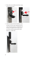
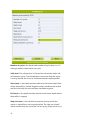
1
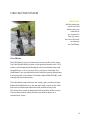
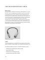
FIELD MICROPROFILING SYSTEM USER MANUAL
Field MicroProfiling System User Manual
Copyright © 2015 · Unisense A/S
Version October 2015
FIELD MICROPROFILING SYSTEM
USER MANUAL
UNISENSE A/S
4
TABLE OF CONTENTS
WARRANTY AND LIABILITY . . . . . . . . . . . . . . . . . . . . . . . . . . . . . . . . . . . . . . . . . . . . . . . . . . . . . . . . . . . . 6
Warning6
Warranty and Liability 6
Repair or Adjustment 6
SensorTrace Suite software
6
CONGRATULATIONS WITH YOUR NEW PRODUCT . . . . . . . . . . . . . . . . . . . . . . . . . . . . . . . . . . . . . . 8
Support, ordering, and contact information
8
OVERVIEW . . . . . . . . . . . . . . . . . . . . . . . . . . . . . . . . . . . . . . . . . . . . . . . . . . . . . . . . . . . . . . . . . . . . . . . . . . . . . 9
Properties of the Field MicroProfiling System
Software for the Field McroProfiling System
10
11
FIELD MICROSENSOR MULTIMETER . . . . . . . . . . . . . . . . . . . . . . . . . . . . . . . . . . . . . . . . . . . . . . . . . . 12
Internal battery
Specification Field Microsensor Multimeter (FMM) 13
14
FIELD MOTOR SYSTEM . . . . . . . . . . . . . . . . . . . . . . . . . . . . . . . . . . . . . . . . . . . . . . . . . . . . . . . . . . . . . . . 15
Field Motor
Sensor holder
Bracket for stepless positioning of the motor
Specification for Field Motor
IN SITU AND FIELD STAND . . . . . . . . . . . . . . . . . . . . . . . . . . . . . . . . . . . . . . . . . . . . . . . . . . . . . . . . . . .
FIELD MICROSENSORS AND CABLES . . . . . . . . . . . . . . . . . . . . . . . . . . . . . . . . . . . . . . . . . . . . . . . . .
EXTERNAL UNITS . . . . . . . . . . . . . . . . . . . . . . . . . . . . . . . . . . . . . . . . . . . . . . . . . . . . . . . . . . . . . . . . . . . .
SETTING UP IN THE FIELD . . . . . . . . . . . . . . . . . . . . . . . . . . . . . . . . . . . . . . . . . . . . . . . . . . . . . . . . . . .
SETTING UP IN THE LABORATORY . . . . . . . . . . . . . . . . . . . . . . . . . . . . . . . . . . . . . . . . . . . . . . . . . . .
ASSEMBLY PROCEDURE 1D MOTORIZED SYSTEM . . . . . . . . . . . . . . . . . . . . . . . . . . . . . . . . . . . .
ASSEMBLY PROCEDURE 2D MOTORIZED SYSTEM . . . . . . . . . . . . . . . . . . . . . . . . . . . . . . . . . . . .
PROFILING SEQUENCE . . . . . . . . . . . . . . . . . . . . . . . . . . . . . . . . . . . . . . . . . . . . . . . . . . . . . . . . . . . . . . .
1D Motorized profiling
2D Motorized profiling
15
16
17
17
18
20
22
23
25
27
29
31
31
35
STORAGE AND MAINTENANCE . . . . . . . . . . . . . . . . . . . . . . . . . . . . . . . . . . . . . . . . . . . . . . . . . . . . . . 38
TROUBLESHOOTING . . . . . . . . . . . . . . . . . . . . . . . . . . . . . . . . . . . . . . . . . . . . . . . . . . . . . . . . . . . . . . . . 39
5
WARRANTY AND LIABILITY
This product is for research use only. Not for use in human diagnostic or
therapeutic procedures.
Warning
Microsensors have very pointed tips and must be handled with care, to
avoid personal injury, and only by trained personnel.
Unisense A/S recommends users to attend instruction courses to ensure
proper use of the products.
Warranty and Liability
The Field MicroProfiling System is covered by a one year limited
warranty.
The warranty does not include repair or replacement necessitated by
accident, neglect, misuse, unauthorized repair, or modification of the
product. In no event will Unisense A/S be liable for any direct, indirect,
consequential or incidental damages, including lost profits, or for any
claim by any third party, arising out of the use, the results of use, or the
inability to use this product.
Repair or Adjustment
Sensors and electrodes cannot be repaired. Equipment that is not
covered by the warranty will, if possible, be repaired by Unisense A/S
with appropriate charges paid by the customer. In case of return of
equipment please contact us for return authorization.
For further information please see the documents General Terms of Sale
and Delivery of Unisense A/S, and Warranty and Shipping Information as
well as the manuals for the respective products.
SensorTrace Suite software
Unisense SensorTrace Suite software is checked and validated for the
Windows platform as given in the specification.
Customer must ensure PC is fully updated and no conflicting third party
software is installed. Unisense do not warrant compliance with any
other operating systems, language settings or third party software.
6
For instrumentation and sensors, please refer to our warranty conditions as given in the document “General Terms of Sale and Delivery of
Unisense A/S” found on www.unisense.com
License agreement
The following terms shall apply to the software provided by Unisense
A/S (“Unisense”) in connection with the simultaneous sale to you
(“Customer”) of a Unisense SensorTrace Suite Software.
All rights, title and interest in the software belong to Unisense.
Unisense grants to the Customer a royalty-free, non-exclusive and
non-transferable license to use the software solely in connection with
the Unisense Product purchased from Unisense simultaneously with
the purchase of the software. The Customer undertakes not to copy,
modify, reverse engineer, disassemble or de-compile all or any part of
the software or rent, lease, distribute or sell the software. The Customer
shall, however, be entitled to make one copy of the software for back-up
and recovery purposes for use solely in connection with the Unisense
Products supplied by Unisense together with the software.
Nothing in this License Agreement or any other agreement between
Unisense and the Customer shall be construed as an obligation for
Unisense to provide to the Customer updates of the software. This
License Agreement shall automatically terminate if the Customer
violates the terms of the license. In case of termination of the license the
Customer shall immediately destroy the software and any copy thereof.
Unisense reserves the right to register the license activation and use of
the software license via the internet.
7
CONGRATULATIONS WITH YOUR NEW PRODUCT
The Field MicroProfiling System uses Unisense Microsensors which
are miniaturized Clark-type sensors that facilitate reliable and fast
measurements with a high spatial resolution designed for research
applications in the field and laboratory.
Support, ordering, and contact information
If you wish to order additional products or if you encounter any
problems and need scientific/technical assistance, please do not
hesitate to contact our sales and support team. We will respond to
your inquiry within one working day.
E-mail: [email protected]
Unisense A/S
Tueager 1, DK-8200 Aarhus N, Denmark
Tel: +45 8944 9500
Fax: +45 8944 9549
Further documentation and support is available at our website:
www.unisense.com
Note: If you find errors in this manual or have suggestions to
improvements, do not hesitate to contact us at sales@unisense.
com
8
OVERVIEW
Field and In Situ instruments are excellent tools for studies with
continuous and automated measurements in the field. The Field
MicroProfiling System is the solution for outdoor and laboratory
microsensor research. The Field Microsensor Multimeter and Field
Motor are robust and designed for outdoor measurements right
where the action takes place. With the waterproof motor and
sensor, splash proof meter, and 5 m of field sensor cable length,
studies in the field and at shallow water can be carried out without
worrying about protecting your setup against water and weather.
The Field MicroProfiling System can be deployed in the environment and can stay deployed for up to 20 hours, depending on
the measurements and power access. An external battery extends
this by 20 hours.
The Field MicroProfiling System is designed for 1D or 2D profiling
with a spatial resolution down to 10 µm. The system can be
expanded to fit specific customer requirements depending on the
scope of research with microsensor measurements.
The microsensors for the Field MicroProfiling System are all
equipped with splash proof connectors and shielded cables
which lead the microelectrode signals into the Field Microsensor
Multimeter where they are amplified.
The Field MicroProfiling System typically consists of the following
main products:
• Field Microsensor Multimeter
• Field Motor system
• In Situ or Field Stand
• Field microsensors and cables
• SensorTrace Suite and Programming Tool
software
9
Properties of the Field MicroProfiling System
• Portable units for outdoor and laboratory
studies
• Outdoor and water resistant system
• Splash proof 8 channel amplifier with plug
and play sensor connectors
–– 5 x pA, 2 x mV and 1 x temperature channel
–– Built-in fully programmable datalogger
–– Direct manual, PC controlled or autonomous operation
• Field Motor
–– Profiles in 1D or 2D
–– High spatial resolution (10 µm)
• Spear and stand for a stable mount of Field
Motor in field and laboratory
• Sensors available: O2, H2, N2O, NO, NOx-, pH,
H2S, temperature and Redox with 5 m sensor
cables and splash proof connectors
• External Units (extra)
–– External battery and charger
–– Field MicroOptode Meter and Field
MicroOptodes
10
Software for the Field McroProfiling System
SensorTrace Profiling is the profiling program from the Unisense
SensorTrace Suite software package. It is for laboratory use of the
Field Multimeter System and for data handling. It offers time series
data logging along a path, it can visualize these measurements
and calculate activity rates.
The intuitive Programming Tool software is for advanced use of
the Field MicroProfiling System. Here, more advanced sequences
can be built and loaded to the Field Microsensor Multimenter.
In the following, the main products of the Field MicroProfiling
System are described briefly. For more information on the Field
Microsensor Multimeter please see the Field Microsensor Multimeter Manual. Information on the SensorTrace Profiling software
is found in SensorTrace Suite manual and information on how to
build advanced sequences and how these are added on to the
Field Microsensor Multimeter is found in the Programming Tool
manual.
11
FIELD MICROSENSOR MULTIMETER
The Field Microsensor Multimeter executes and logs the analogue
signals from the microsensors, position data from the motors and
all digital signals from external equipment. For the synchronization of these signals the Field Microsensor Multimeter uses high
speed background data sampling.
The Field Microsensor Multimeter is built for outdoor use, it is
splash proof and completely protected against dust and salt.
Field Microsensor Multimeter channels 1 to 5 are for amperometric
microsensors e.g. O2, H2S and H2. Some of these Microsensors are
automatically recognized and the correct polarization is set.
12
The Field Microsensor Multimeter channel 6 and 7 are highimpedance millivolt channels for potentiometric microsensors
such as pH and redox. Channel 8 is a temperature channel.
The Field Microsensor Multimeter can be used as a stand-alone
instrument, PC controlled or with autonomous operation. The
standard Field Microsensor Multimeter has 8 GB data capacity
corresponding to more than 120 days of data acquisition at 10 Hz.
The Graphical 7” LED display has 800 x 480 pixels and 18 bit color
with high contrast optimized for an optimal reading in the field.
Internal battery
The Field Microsensor Multimeter has an internal Li-Ion battery
that will allow the system to run for up to 20 hours at 25⁰C.
Although the system runs perfectly on the charger, e.g. in a
laboratory setting, the self heating of the system during use can be
close to 40°C. It has an intelligent charging circuit that lowers the
charging effect or even stops charging as the system temperature
approaches 40°C. This results in prolonged charging time. In an
environment with high temperatures it is recommended to turn of
the Field Microsensor Multimeter during charging.
IMPORTANT
The Battery can
ONLY be charged at
operating temperatures from 0-40°C.
Also note that the Field Microsensor Multimeter is gray and if
left charging in direct sunlight e.g. in the open field, the internal
temperature will quickly increase above 40°C. Protect the
instrument against sunlight and cover the case with a wet towel
for cooling.
Further information on the Field Microsensor Multimeter is found
in the Field Microsensor Multimeter manual.
13
Specification Field Microsensor Multimeter (FMM)
• Amplifier: Standard configuration 5 x pA, 2 x
pH/mV, 1 x temp.
• Two motor control channels
• Control 3-serial RS-232/UART, I/O 4 x digital
3.3V
• Power supply: Battery – internal Li-Ion or External voltage 9V (5-28V), 13Ah, 100Wh. Run
time at 25°C approx. 20h at normal usage.
• A/D converter: Resolution 16 bit, sampling
frequency 10 kHz.
• Data rate up to 10 samples/sec.
• Display: Graphical 7” LED display, 18 bit color/
high contrast, 800 x 480 pixel.
• Dimensions 350 x 300 x 148 cm (138 x 118 x
58 in) (W x D x H), Approx. 8,5 kg (19 lbs)
• Temperature range, operating conditions -10
°C to 50 °C.
14
FIELD MOTOR SYSTEM
IMPORTANT:
Add the protection
cap on the Field
Motor connector
when not in
use, to protect it
from e.g. moist,
dust and salt which
can damage
the Field Motor.
Field Motor
The Field Motor consists of the motor house and the linear stage.
The Field MicroProfiling System is designed to function with 1 or 2
motors with full positional feedback and it can therefore be used
for profiling in a 1D (z-axis) and 2D (z- and x-axis) direction. The
Field Motor/s are controlled from the Field Microsensor Multimeter
and connected via the Motor Controller cable (FMM-MOT001) with
waterproof Lemo connectors.
The Field Motor house contains the motor, gear, and the encoder.
When the Field Motor runs, the encoder sends signals to the Field
Microsensor Multimeter about the axle rotation at any time.
This allows the system to keep track of the position of the sensors.
The encoder controls vertical motor movements down to a
resolution of 10 μm.
15
Sensor holder
The adjustable sensor holder can hold 6 sensors. This makes it
possible to profile with 6 sensors simultaneously. The whole sensor
holder can, when mounted on the linear stage, be adjusted forth
and back. The fixation screws at each sensor hole make it possible
to mount the sensors so that all sensor tips are aligned. The sensor
placed in the middle can be adjusted using an Allen key.
For laboratory use the Micromanipulator (MM33) can be mounted
on to the Motor stage, instead of the sensor holder, by using four
screws.
16
Bracket for stepless positioning of the motor
The Field Motor is mounted on to the In Situ Stand (IS 19) or
the Field Stand (FS) using the supplied bracket. The stepless
adjustment of the bracket on the spear makes it possible to place
the Field Motor at the exact position of your choice.
Specification for Field Motor
• Stage profiling length: 20 cm (8 in)
• Step resolution (uni-directional): 10 µm
• Sensor holder: included – mount for 6 sensors
CAUTION!
Do not try to
manipulate the
motor manually
while powered
• Supplier Bracket for Field Stand (FS) or In Situ
Stand (IS 19)
• 2D profiling (optional)
• Dimensions: Dimensions 52 x 7.5 x 5 cm (20.5
x 3 x 2 in) (W x D x H), Approx. 3 kg (7 lbs)
17
IN SITU AND FIELD STAND
The In Situ Stand is formed as a spear and can be used alone (IS 19)
or mounted on a stable base (FS) e.g. for laboratory use.
When used alone, the spear should be placed with the pointed
end directly in the sediment in a stable way. The Field Motor is
mounted on the spear using the supplied bracket.
The Field Stand (FS) is a robust support for mounting the Field
Motor when using it in the laboratory. It is provided with a stable
base, In Situ Stand (IS 19) and two smaller round metal poles
for mounting samples and other components relevant for the
experiment.
18
Specification In Situ Stand (IS19)
• Weight: 2.7 kg (6 lbs)
• Height: 70 cm (28 in)
• Fixation holes: thread M6, spacing between
holes 5 cm (2 in)
• Surface treatment: corrosion resistant stainless steel.
Specification Field Stand (FS)
• Weight: 18 kg (40 lbs)
• Dimensions: 20 cm x 30 cm x 71 cm (8 x 12 x
28 in) (W x D x H)
• Fixation holes: thread M6, spacing between
holes 5 cm (2 in)
• Chemically and physically resistant epoxy
paint.
19
FIELD MICROSENSORS AND CABLES
Microsensors
Unisense offers a variety of microsensors that measure O2, H2, N2O,
NO, NOx-, pH, H2S, temperature and redox. The microsensors are
connected directly into the Field Microsensor Multimeter with
full recognition and polarization setup for most sensor types. The
microsensor signal is in the pico ampere and micro voltage range
and is amplified within the Field Microsensor Multimeter.
All Field sensors come with LEMO™ splash proof connectors and
a 5 m long sensor cable (optional up to 10 m). For laboratory use
the laboratory sensors can be connected to the Field Microsensor
Multimeter using FMM-to-Lemo Adaptor.
FMM to Lemo Adapter
Cables
The cable connectors are rated for 5 meter depth and the motor
cable is rated for 10 meter depth. The standard cable length is 5 m.
The following cables are used in a Field MicroProfiling System:
• Field Microsensor Multimeter to Motor cable
(type FMM-MOT001)
• Field Microsensor Multimeter to PC
communication (type FMM-COM001)
20
–– A 50-70 m waterproof version is available
(type FMM-COM002)
• LAN communication cable (type FMMCOM003).
• Charger (FMM-CHG001)
• External DC power cable (type FMMPOW001) with variable pin-out connection
e.g. alligator clips.
• External Battery cable (FMM-BAT001).
21
EXTERNAL UNITS
External battery (optional)
For long term deployments (more than 20 hours of constant
measurements with several microsensors and normal use of
screen and Field Motor) an external power supply is necessary e.g.
Unisense External Battery, a car battery, or a generator. Please refer
to the Field Microsensor Multimeter manual for external power
specification.
Other units (optional)
The Field MicroProfiling System can be expanded to interface
with other external units e.g. the Field MicroOptode Meter. Three
serial communication ports and one digital input/output are
available depending on the hardware and software configuration.
For instance an optical oxygen sensor can be useful to make an
independent check of the ambient oxygen concentration. Up to 3
serial instruments can be connected at the same time.
22
SETTING UP IN THE FIELD
The following will describe a typical profiling set-up in the field:
Before going into the field
1. Make sure that the battery (internal and/or
external) of the Field Microsensor Multimeter is charged.
2. Make sure that the correct sequences have
been added on to the Field Microsensor
Multimeter and that they work properly.
In the field
1. Turn on the Field Microsensor Multimeter, it
will take a few seconds to boot.
2. Connect the microsensors to the Field
Microsensor Multimeter.
23
3. Polarize and calibrate the sensors as specified in the relevant microsensor manual.
4. Place the spear in a stable position in the
field. Mount the Field Motor on the spear
bracket and place it onto the spear so it has
an appropriate distance from the sample
in order for the sensors and linear stage to
manoeuvre correctly.
5. Place the Field Microsensor Multimeter at a
safe place near the Field Motor.
6. Connect the Field Motor cable to the Field
Microsensor Multimeter’s Motor 1 channel
using the FMM-MOT001 cable. If a second
Field Motor is used, connect it to Motor 2
channel.
7. Place the microsensors in the sensor holder
on the Field Motor with the tip a few centimeters above the sample. Move the sensor
vertically (vertically and horizontally in a
2D system) to the desired location with the
Motor 1 (and Motor 2) control. Be careful
not to break the microsensor tip.
8. Reset the motor position to 0 mm for each
axis on the Field Microsensor Multimeter
and start the sequence.
24
SETTING UP IN THE LABORATORY
1. Make sure that the internal battery of the
Field Microsensor Multimeter is charged or
power directly using the supplied charger.
2. Connect the Field microsensors to the
Field Microsensor Multimeter. For laboratory microsensors use the FMM- to - LEMO
Adaptor. Polarize the sensors as specified in
the relevant microsensor manual.
3. Assemble the Field Stand (FS) by screwing
the spear (IS19) onto the base of the stand.
Mount the spear with the pointed end up,
using the two large screws placed on the
corner of the FS base.
4. Glide the bracket with the Field Motor
onto the spear and tighten the screws on
the bracket so the Field Motor has a stable
25
hold and an appropriate distance from the
sample, in order for the sensors and linear
stage to manoeuvre correctly.
5. Connect the 1D Field Motor cable to the
Field Microsensor Multimeter’s Motor 1
channel using the FMM-MOT001 cable. If
a second Field Motor is used, connect it to
the Motor 2 channel.
6. In the lab it is possible to run a profiling
sequence directly from the computer
when the Field Microsensor Multimeter
and the computer are connected with the
provided FMM-COM01 cable. For this you
will use the SensorTrace Profiling software
(if purchased). Alternatively, you can run
the sequence autonomously directly from
the Field Microsensor Multimeter. In this
case you have to make sure that the correct
profiling sequence is activated on the Field
Microsensor Multimeter
7. Calibrate the sensors as described in the
relevant sensor manual.
8. Place the microsensors in the sensor holder
of the Field Motor with the tip a few centimeters above the sample. Move the sensor
vertically (vertically and horizontally in a
2D system) to the desired location with the
Motor 1 (and Motor 2) control. Be careful
not to break the microsensor tip.
9. Make sure the motor position has been
reset e.g. to 0 mm on the Field Microsensor Multimeter and start the selected or
activated sequence.
26
ASSEMBLY PROCEDURE 1D MOTORIZED SYSTEM
1. Connect the Field Motor to the Field Microsensor Multimeter using the FMM-MOT001
cable and move the stage to an end position. The 4 holes for mounting the Field
Motor to the bracket should be visible.
2. Mount the Field Motor stage to the bracket
using an Allen key and the four small
screws.
27
3. Mount the sensor holder on the linear stage
using the large screw.
4. Glide the bracket with the Field Motor onto
the spear with the motor head pointing upwards. Place the motor at a safe position on
the spear and tighten the two large screws
on the front of the bracket until the Field
Motor has a stable hold.
28
ASSEMBLY PROCEDURE 2D MOTORIZED SYSTEM
1. Follow step 1 and 2 from the 1D assembly
procedure.
2. Remove the metal plate from the stage by
removing the 4 screws with an Allen Key.
3. Mount Motor 2 (x-motor) horizontally on
top of the Motor 1 stage and mount it using
the four screws.
4. Mount the sensor holder on to the linear
stage and turn the sensor holder so it will
move the sensors in the same direction as
Motor 1 (z-motor)
29
5. Glide the bracket placed on Motor 1 stage
onto the spear with the motor head of
Motor 1 pointing upwards and the sensor
holder pointing downwards. Place the motor a safe position on the spear and tighten
the two large screws on the front of the
bracket until the Field Motors have a stable
hold.
30
PROFILING SEQUENCE
A typical application of the Field MicroProfiling System is to profile
along the depth transect. This is done by repeatedly moving the
motor a small distance, waiting a period of time for signals to
stabilize, and then logging data. The following gives a step by step
guide to make a simple sequence with this behavior. Advanced
profiling sequences can be made by using the Programming Tool
software. For further information about the Programming Tool
software please see the Programming Tool user manual.
1D Motorized profiling
Here we will describe how to make a 1D motorized profile. In the
example we will profile from a 0 depth and 12 mm into the sample
with a resolution of 50 µm. When the profile is finished the sensor
will be placed at a safe position 5 mm above the 0 depth. The
profile should only run one time with one replicate at each depth.
The 1D profiling sequence is made in the following way:
1. Select the Sequence window on the Field
Microsensor Multimeter
2. Select Add Sequence and Profiling 1D
3. Name your profiling sequence and add
(optional) an estimated time (in seconds)
for the profiling sequence. The sequence
will be listed in the Sequence window.
4. Add the different parameters in the motorized 1D profiling program – see example.
31
Number of cycles: Set the desired number of cycles here. In a 1D
setting a profile is identical to one cycle.
Safe (mm): The safe position is the position where the motor will
rest between cycles. The safe position is to ensure that the sensor
is resting outside the tissue or sediment between replica profiles.
Start (mm): is the depth position relative to the Home depth from
where the profile is started. Negative values are above the surface
and thus normally the start position should be negative.
End (mm): is the depth position relative to the Home depth where
the profile is stopped.
Step size (mm): is the vertical increment in mm by which the
sensor is moved from start to end position. The step size should
not be smaller than the size of the sensor tip e.g. if the sensor has a
32
tip size of 50 µm the step sizes should not be smaller than 50 µm.
Replicates: Enter the number of measurements that should be
performed at each depth.
Wait before measure (s): When the position during a profile
is reached, during a profile, the system will wait for a period of
seconds before it starts measuring. This is to ensure that the sensor
signal is stable before the measurements starts. The time varies
depending on the sensor. When profiling with multiple sensors the
response time of the slowest sensor should be entered.
Measure period (s): sets the duration of the measurement at each
position. Each measurement will be an average value over this
period of time. When making profiles in a unstable environment,
it can be helpful to average over a longer period, i.e. increase the
measure period. The setting should be set to match the measuring
condition.
Delay Between (s): is used when starting a profile and during
repeated profiles. Each time a cycle is started, the sensor is placed
in the Safe position and the profile is started after a delay period
given here.
Press Next to continue.
5. In the Sequence configuration you define
whether the sequence should have a delay
or not and add how long (in seconds) the
delay, if any, should be. Press Done when
the profiling sequence is ready.
6. Place the Field Motor at your start position.
Reset the position to 0 mm under the ‘Motor’ window in the ‘Advanced control’ menu.
7. Run the selected sequence by selecting
Run. Alternatively press Mark as Active and
then activate the Profiling Sequence by
33
pressing Start.
8. Profiling data made on the Field Microsensor Multimeter can be imported into the
SensorTrace Profiling software for activity
calculations.
You load the data in the following way:
Connect the Field Microsensor Multimeter
to the computer and make sure that ‘Network mode’ in the Settings window on the
Field Microsensor Multimeter is showing
‘Direct’. Start the SensorTrace Profiling software, select ‘Download Profiling experiment
from device’ in the File tab and mark the
experiments you want to download from
the Field Microsensor Multimeter. Open
the downloaded file (they are stored in the
formate *.upro). The data are now imported
into the SensorTrace Profiling software and
further data handling can be made.
34
2D Motorized profiling
For a 2D motorized profiling sequence along a depth and side
gradient, the sequence can be programmed in the following way:
Here we profile into a sample with a step size of 100 µm 20 mm
into the sample, hereafter Motor 2 will move the sensor 1 cm 10
times in the x-axis making a profile at each depth. After the 2D
profiling is finished Motor 1 and Motor 2 are placed at starting
point 0 mm. The 2D profiling sequence is made in the following
way:
1. Select the Sequence window on the Field
Microsensor Multimeter and place the
green selecting bare on any sequence and
press Select
2. Select Add Sequence and press Profiling 2D
3. Name your profiling sequence and add
(optional) an estimated time (in seconds)
for the profiling sequence. The sequence
will be listed in the Sequence window.
4. Add the different parameters in the motorized 2D profiling program – see example.
A detailed description of the different
parameters is found under the ‘1D profiling
sequence’ section.
35
Press Next to continue
5. In the Sequence configuration you define
if the sequence should have a delay or not
and if so add how long (in seconds) the
delay should be. Press Done, when the 2D
profiling sequence is ready.
6. Place the Field Motor 1 and Field Motor 2 at
your start position. Reset the position to 0
mm under the ‘Motor’ tab in the ‘Advanced
control’ menu for both Motor 1 and Motor
2.
7. Run the selected sequence by selecting
Run. Alternatively press Mark as Active and
36
then activate the Profiling Sequence by
pressing Start.
8. Profiling data made on the Field Multimeter
can be imported to the SensorTrace Profiling software for activation calculations. You
load the data in the following way: Connect
the Field Microsensor Multimeter to the
computer and make sure that ‘Network
mode’ in the Settings Tab on the Field
Microsensor Multimeter is showing ‘Direct’.
Start the SensorTrace Profiling software,
select ‘Download Profiling experiment from
device’ in the File tab and mark the experiments you want to download from the Field
Microsensor Multimeter. Open the downloaded file (they are stored in the formate
*.upro). The data are now imported into the
SensorTrace Profiling software and further
data handling can be made.
37
STORAGE AND MAINTENANCE
Remember to add protection caps on all channels before rinsing
the Field Microsensor Multimeter and Field Motor. Avoid water,
salt and dust to get into the connectors as this can damage the
instrument.
Field Microsensor Multimeter and Field Motor:
Rinse sand, dirt and salt of the Field Microsensor Multimeter with
water and dry it afterwards.
Rinse the mounting spear and the motor house with water after
use. To remove stains, use mild soap only. To reduce wear, it is
important to rinse any sand particles etc. from the axle.
38
TROUBLESHOOTING
Problem
Possible cause
Solution
Field motor runs off spindle.
The motor has moved too far up or down.
Apply finger pressure on the slide block in the motors movement
direction. Apply the pressure until the motor is attached the
spindle again and hold the pressure until the motor has moved for
about 4 cm.
39
UNISENSE, DENMARK
www.unisense.com · [email protected]