1
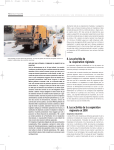
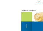
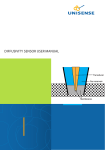
NITRIC OXIDE SENSOR USER MANUAL
NITRIC OXIDE SENSOR USER MANUAL
UNISENSE A/S
Nitric oxide sensor user manual
Copyright © 2014 · Unisense A/S
Version January 2014
TABLE OF CONTENTS
NITRIC OXIDE SENSOR USER MANUAL . . . . . . . . . . . . . . . . . . . . . . . . . . . . . . . . . . . . . . . . 1
WARRANTY AND LIABILITY . . . . . . . . . . . . . . . . . . . . . . . . . . . . . . . . . . . . . . . . . . . . . . . . . . . 6
CONGRATULATIONS WITH YOUR NEW PRODUCT! . . . . . . . . . . . . . . . . . . . . . . . . . . . . 7
Support, ordering, and contact information
7
OVERVIEW . . . . . . . . . . . . . . . . . . . . . . . . . . . . . . . . . . . . . . . . . . . . . . . . . . . . . . . . . . . . . . . . . . . . 9
Working principle
9
GETTING STARTED . . . . . . . . . . . . . . . . . . . . . . . . . . . . . . . . . . . . . . . . . . . . . . . . . . . . . . . . . . 10
Unpacking a new sensor
Grounding the set-up
Polarization
Pre-polarization
Calibration
10
10
11
11
12
STOCK SOLUTIONS AND NO DONORS . . . . . . . . . . . . . . . . . . . . . . . . . . . . . . . . . . . . . . . 14
MEASUREMENTS . . . . . . . . . . . . . . . . . . . . . . . . . . . . . . . . . . . . . . . . . . . . . . . . . . . . . . . . . . . . 17
Mounting of the sensors
Interference
17
18
ADVANCED USE OF THE NO SENSORS . . . . . . . . . . . . . . . . . . . . . . . . . . . . . . . . . . . . . . . 19
STORAGE AND MAINTENANCE . . . . . . . . . . . . . . . . . . . . . . . . . . . . . . . . . . . . . . . . . . . . . 20
Storage
Cleaning
20
20
REFERENCES . . . . . . . . . . . . . . . . . . . . . . . . . . . . . . . . . . . . . . . . . . . . . . . . . . . . . . . . . . . . . . . . . 21
TROUBLE SHOOTING . . . . . . . . . . . . . . . . . . . . . . . . . . . . . . . . . . . . . . . . . . . . . . . . . . . . . . . 22
WARRANTY AND LIABILITY
Notice to Purchaser
This product is for research use only. Not for use in human diagnostic or
therapeutic procedures.
Warning
Microsensors have very pointed tips and must be handled with care to
avoid personal injury and only by trained personnel.
Unisense A/S recommends users to attend instruction courses to ensure
proper use of the products.
Warranty and Liability
The NO microsensor is covered by a 90 days limited warranty.
Microsensors are a consumable. Unisense will only replace dysfunctional
sensors if they have been tested according with the instructions in the
manual within 14 days of receipt of the sensor(s).
The warranty does not include repair or replacement necessitated by
accident, neglect, misuse, unauthorized repair, or modification of the
product. In no event will Unisense A/S be liable for any direct, indirect,
consequential or incidental damages, including lost profits, or for any
claim by any third party, arising out of the use, the results of use, or the
inability to use this product.
Unisense mechanical and electronic laboratory instruments must
only be used under normal laboratory conditions in a dry and clean
environment. Unisense assumes no liability for damages on laboratory
instruments due to unintended field use or exposure to dust, humidity
or corrosive environments.
Repair or Adjustment
Sensors and electrodes cannot be repaired. Equipment that is not
covered by the warranty will, if possible, be repaired by Unisense A/S
with appropriate charges paid by the customer. In case of return of
equipment please contact us for return authorization.
For further information please see the document General Terms of Sale
and Delivery of Unisense A/S as well as the manuals for the respective
products.
6
CONGRATULATIONS WITH YOUR NEW PRODUCT!
Support, ordering, and contact information
The Nitric Oxide (NO) microsensor is a miniturized sensor for
measuring the partial pressure of NO gas in the nanomolar range.
If you wish to order additional products or if you encounter any
problems and need scientific/technical assistance, please do not
hesitate to contact our sales and support team. We will respond to
your inquiry within one working day.
E-mail: [email protected]
Unisense A/S
Tueager 1
DK-8200 Aarhus N, Denmark
Tel: +45 8944 9500
Fax: +45 8944 9549
Further documentation and support is available at our website
www.unisense.com.
REPLACEMENT OF SENSORS
Unisense will replace sensors that have been damaged during shipment provided that:
•
The sensors were tested immediately upon receipt in accordance with the delivery note
and the manual
•
The seal is still intact.
•
The sensors are returned to Unisense for inspection within two weeks.
•
The sensors are correctly packed for return to Unisense, in accordance with the note
included in the sensor box.
7
THIS MANUAL COVERS THE FOLLOWING SENSORS
NO10 (tip diameter <20 µm)
NO100 (tip diameter 70-110 µm)
NO-MR (designed for use with microrespiration system)
NO-N (Needle-type NO sensor)
NO-R (NO sensor with protective cap)
NO-spec - NO sensors with customer specified specifications
RECOMMENDED METERS FOR NO SENSORS
One-channel meter: Microsensor Monometer
Multi-channel meter: Microsensor Multimeter
8
OVERVIEW
The Unisense nitric oxide (NO) microsensor is designed for
research applications within physiology, biotechnology, environmental sciences, and related areas.
The Unisense NO microsensor can be made with
• a small tip size (10 μm), which ensures excel-
WARNING
Unisense sensors
are neither
intended nor
approved for use
on humans
lent response time and insignificant stirring
sensitivity and makes it possible to make
reliable and fast measurements with high
spatial resolution
• a larger tip size (>100 μm) which allows for
low detection limit (approx. 2-3 nM)
For non-destructive measurements, the sensor should be
designed to have a small tip; for other applications the sensor is
designed for maximum sensitivity.
Working principle
The NO sensor is a miniaturized Clark-type sensor which must
be connected to a high-sensitivity picoammeter. The measuring
anode inside the sensor tip is polarized against an internal
reference electrode by the picoammeter. Driven by the external
partial pressure, NO from the environment will penetrate the
sensor tip membrane and reach the anode surface where it is
oxidized. The picoammeter converts the resulting oxidation
current to a voltage signal.
The Unisense NO sensor has an extremely low consumption
compared to other standard NO sensors. The maximum
consumption (i.e. for the NO100) is 935 femtomol/hour which
corresponds to 0.1%/hour in a 1ml 0.1uM NO sample.
9
GETTING STARTED
Unpacking a new sensor
When receiving a new NO microsensor, remove the shockabsorbing grey plastic net. Please do not remove the seal and
protective tube before the following steps are successfully
completed.
WARNING WARNING WARNING WARNING WARNING
It is extremely important to ground the NO sensor before use.
Otherwise the sensor is very susceptible to electrical disturbances
and in some cases will be damaged. Please read the information
and directions in this manual and contact Unisense if you are in
doubt of what to do.
Grounding the set-up
Before connecting the NO sensor, it is important to ground the
set-up, both the measurement media and the picoammeter.
Grounding the set-up means to stabilize its electrical potential
to avoid noisy signals and/or damage to the sensor. Grounding is
done by connecting any media/liquids the sensor will touch to the
ground connection of the picoammeter using the provided wire,
and connecting the ground plug of the picoammeter to an earth
line. An earth line can often be found in electrical outlets, alternatively a good electrical connection to a water pipe may be used. If
an earth line is not available, at least keep media and picoammeter
ground connected.
Technical details
The tip membrane of a microsensor serves as an electrical
barrier which minimizes the effect of electrical disturbances. If,
however, a sufficiently high electrical potential has built up across
the membrane, the resistance is not high enough to prevent a
discharge of electricity across the membrane. Often this happens
when a person carrying electrical charges touches the set-up.
The discharge across the membrane can cause a permanent
10
WARNING
Do not remove the
seal and protective
plastic tube
before these steps
and calibration
are successfully
completed.
breakdown of the electrical resistance of the membrane and
subsequently, electrical noise e.g. 50/60 Hz noise from mains
power installations can then affect the signal severely. As NO
sensors have particularly thin membranes, they are more prone to
this problem than other sensors.
See also the Troubleshooting section.
Polarization
The signal from the NO sensor is a small current in the picoampere
range. Therefore the NO sensor must be connected to a polarizing picoammeter (e.g. a Microsensor Monometer, a Microsensor
Multimeter, or the Unisense PA2000).
NO sensors should be polarized at +1.25 V. The polarization
voltage is set in the amplifier. For details on how to set and check
the polarization, consult the user manual of the picoammeter
to be used. If you are using a PA2000 amplifier, please check the
polarization voltage before connecting the sensor, since incorrect
polarization may destroy the sensor.
Pre-polarization
When the sensor is not in use, NO will build up inside the electrolyte. This must be removed order to obtain a stable zero current
as background for calibrations and measurements. and thus stable
operation of the sensor is possible. Therefore, a period of polarization is necessary before you can use the sensor. This is called
the pre-polarization period.
When the NO sensor is connected to the picoammeter and
polarization of the sensor is initiated, the signal will be very high,
drop rapidly over the first few minutes, and then drop more slowly.
For new sensors and sensors that have not been in use for several
days, it takes up to 24 hours for the signal to stabilize. After shorter
periods without polarization, the sensor should be polarized until
it has exhibited a stable signal for 10 minutes.
If the signal does not stabilize below 20 pA at room temperature,
please look in the ‘Trouble-shooting’ section of this manual.
11
Calibration
Before concentration measurements can be performed, a
calibration should be performed.
The NO sensor responds linearly to NO from zero up to a
maximum linear concentration. Thus, a two-point calibration is
sufficient. The maximum linear concentration depends on the
application the sensor is designed for. The calibration standards
should be within the linear range for the sensor in question and
cover the expected concentration range to be measured, e.g. zero
NO (0% atm.) and 1 μM.
Using NO stock solution
Please see the following section “Stock solutions and NO donors”
for instruction on preparation.
Zero reading
Note the signal, S0, in water without any NO (or interferents).
(Note: Be careful if you try to use gas-sparged water which has
contained NO. NO will convert to NO2- in the presence of oxygen
and if the water is acidic, HNO2 is formed. HNO2 interferes on the
NO sensor and is not easily removed by sparging the water).
High reading
NO will react spontaneously with oxygen, so an NO calibration solution should be made in an anoxic environment. A
continuously anoxic solution can be maintained in the following
manner: Get a vessel – preferably made of glass – with a lid with
two holes in it (e.g. Unisense CAL300). One hole is for sparging
with oxygen free gas (e.g. N2 gas), the other hole is for inserting the
NO sensor. The vessel is filled ¾ with neutral pH buffered water,
and there is thus a headspace under the lid. The sensor is placed
through the sensor hole in the lid with its tip a few cm inside the
buffer. The oxygen-free gas is led through the gas-sparging hole
through a long pipe or needle that opens at the bottom of the
vessel. Bubbling oxygen-free gas through the buffer solution
will remove all oxygen. The gas should stream fast enough to
effectively flush the headspace, preventing atmospheric oxygen
from entering through any of the holes in the lid. For the Unisense
calibration chamber CAL300, 5 minutes of bubbling at a rate of 0.5
12
IMPORTANT
Calibration must
be performed after
pre-polarization
when the sensor
signal has
stabilized.
Always use a
calibration solution
with the same
temperature and
salinity as the
sample solution.
L gas per minute is sufficient to drive out 99% of the oxygen.
After the buffer is stripped of oxygen, the gas pipe is retracted
somewhat such that it opens in the headspace. An small volume
of an NO stock solution (see Stock solution and NO donors section
below) is injected into the buffer. The buffer is stirred briefly to
distribute the NO evenly. Stirring can be done with a) a glass rod
through the gas flushing hole, b) brief bubbling with the gas pipe,
or c) with a stirrer magnet when the vessel is placed on a stirrer
plate. The continued gas flow in the headspace will keep oxygen
out, but will only slowly remove NO from the buffer (as opposed
to bubbling which will remove NO quickly). The high calibration
reading (S1) is noted, corresponding to the concentration (C1)
calculated from the stock concentration and the dilution ratio.
To convert a signal S from partial pressure to the corresponding
concentrations of NO (C), perform a linear conversion:
C = (C1 * S -C1S0)/ (S1-S0)
WARNING
Bubbling of
water with gas
may cause the
water to change
temperature
due to the gas
temperature
or evaporative
cooling. Monitor
the temperature
to find a suitable
bubbling rate,
which does
not does not
change the water
temperature
significantly.
If you use Unisense software, the calibration calculations can
be performed by the software. Consult the software manual for
details.
Check and repeat calibration at appropriate time intervals
to ensure that all measurements can be calibrated to correct
concentrations. When the sensor is new, you may need to calibrate
more often, while an older extensively used sensor may require
calibration only every 24 hours or less. To minimize the need
for calibration, it is recommended to keep the sensor polarized
between measurements.
The membrane permeability of NO microsensors changes with
time, so a change in signal of up to 50% may occur over months.
This does not affect the quality of the measurements as long as
the sensor is regularly calibrated.
Using NO donors
Some researchers prefer making calibrations with so-called NO
donors. We will not describe a procedure here. However, references can be found in the Stock solutions and NO donors section.
13
STOCK SOLUTIONS AND NO DONORS
There are several ways to prepare an NO stock solution
1. Using NO gas:
a. A sealed vial is half-filled with distilled
water or buffer, flushed with argon to
remove oxygen, and the headspace is
finally vacuum-treated. NO gas from a
pressure gas tank is bubbled through a
washing bottle, containing 1 M NaOH.
The bottle captures impurities in the
form of N2O3 and N2O4 gas. The gas
streams long enough to flush all oxygen
out. After the washing bottles, the gas
is lead through a needle. The needle is
led to penetrate the septum in the vial,
filling the headspace with a slight overpressure of NO. Subsequently, the vial is
shaken to equilibrate the headspace NO
with the water/buffer, before the surplus pressure is removed by puncturing
the membrane.
Ref: Methods in Molecular Biology, Vol.
100, Nitric Oxide Protocols. Ed. Michael A.
Thitheradge, Humana Press Inc., Totowa
NJ., p.232:
b. A
researcher implements the above
principle in the following way: bubbles
NO gas from a pressure gas tank
through two washing bottles in series,
containing 5 M NaOH. These bottles
capture impurities in the form of NO2
and NO3 gas. After the washing bottles,
the gas is lead through a long needle
14
that penetrates a septum in a vial. The
vial has a few ml distilled water inside
and the NO gas bubbles through this
water. A second needle through the
septum leads from the headspace to
the exterior to allow the gas to escape.
The set-up is kept in a fume hood. Bubbling for a approx. 15 minutes results in
a clean saturated stock solution of NO in
the vial. This stock is diluted for calibration standards. After the NO production,
the system is flushed for 45 minutes
with Argon, if NO is left in the system it
will attack rubber tubing.
2. Chemical NO synthesis: Another alternative
is NO synthesis from NaNO2 with the following procedure: Concentrated H2SO4 is slowly
added to a N2-flushed mixture of saturated
NaNO2 and KI. This evolves NO gas which
is passed through a wash bottle with 10 M
NaOH to remove traces of NO2. The purified
NO gas is captured in a vial with a membrane which contains a few ml of distilled
water. A second needle through the septum
leads from the headspace to the exterior to
allow the gas to escape.
Ref: Diab et al. 2005. Electrochemical nitric
oxide sensor preparation: a comparison of
two electrochemical methods of electrode
surface modification. Bioelectrochemistry
66:105-110.
15
As an alternative to NO stock solutions, some researchers use the a
compound that can decompose and release NO (NO donor).
1. Ref: Richardson et al. 2006. The nitrosative
stress response of Staphylococcus aureus
is required for resistance to innate immunity. Molecular Microbiology (2006) 61(4),
927–939: “Nitric oxide donating compounds used in this study were obtained
from Alexis Biochemicals (San Diego, CA).
Diethylamine NONO-ate (DEA/NO, t1/2 = 2
min), Proline NONO-ate (ProliNO, t1/2 = 1.8
s), and Diethylethylenediamine NONO-ate
(NOC-12, t1/2 = 100 min) were dissolved to
500 mM final concentration in 0.01 N NaOH
and stored at -80°C. SNAP was resuspended
to a final concentration of 500 mM in DMSO
and aliquots were stored at -80°C. The
conjugate donor compounds diethylamine
(Sigma D-0806), proline (Sigma P-0380), diethylethylenediamine (Aldrich 126942), and
NAP (Aldrich A19008) were diluted to same
concentrations as cognate NONO-ates in
like solvents and stored at -80°C.”
2. For further information on the SNAP
method: Ref: Xhang et al. 2000. Novel Calibration Method for Nitric Oxide Microsensors
by Stoichiometrical Generation of Nitric Oxide
from SNAP. Electroanalysis 12(6):425-428.
16
MEASUREMENTS
Before doing microscale measurements, the seal must be broken
and the protective tube removed. NOTE: this terminates Unisense’s
warranty.
Mounting of the sensors
Although the Unisense microsensors are made of glass, the tip
is flexible and can bend slightly, and the sensors are surprisingly
robust in use in coarse substrates. However, lateral movements
of the sensor when the tip is in contact with a solid substrate
may easily cause the tip to break. Also, due to the small size of
the microsensor tip and to the steepness of gradients in many
environments, even a displacement of the sensor tip of few
microns may change its environment. Therefore, we recommend
that measurements are performed only in a stabilized set-up
free of moving or vibrating devices. We recommend the
Unisense lab stand LS18 and the Unisense micromanipulator
MM-33 (or double MM33-2) for laboratory use. For in situ use we
recommend our in situ stand (IS19) and a micromanipulator or our
automated in situ profiling instruments.
WARNING WARNING WARNING WARNING WARNING
It is extremely important to ground the NO sensor before use.
Otherwise the sensor is very susceptible to electrical disturbances
and in some cases will be damaged. Please read the information
and directions in this manual and contact Unisense if you are in
doubt of what to do.
Electrical noise
The signal of a NO microsensor is very small (10-14 to 10-10 ampere).
Although both the Unisense amplifiers and microsensors in
general are relatively resistant to electrical noise from the
environment, electrical fields may interfere with the sensor signal.
NO microsensors are more susceptible to electrical noise than e.g.
IMPORTANT
Always introduce
and retract the
NO microsensor
axially using a
micro manipulator
and a stable stand
when measuring in
solid or semisolid
substrate like
sediment, tissue,
biofilms, microbial
mats, etc.
IMPORTANT
To resolve the
very small
concentrations
that are most often
of interest, it is
very important to
eliminate electrical
noise as much
as possible. This
can be done by
grounding the
set-up (if you have
a PA2000, you can
place an analog
filter on it.
17
oxygen microsensors, so it is necessary to ‘ground’ the set-up. This
is done by creating an electrical connection between the Ground
connection of the picoammeter and the sample to be studied
(tissue, sediment core water etc.). Also, unnecessary electrical/
mechanical equipment should be switched off and touching
components of the set-up during calibrations and measurements
should be avoided.
On suspicion of sensor damage, repeat calibration and consult
‘Trouble-shooting’.
Interference
The following compounds and physical parameters are known
to exhibit interference on the NO microsensor: HNO2, H2S, light,
temperature. Keep updated on reported interferents on our web
page.
The graph shows a NO sensor response to sequential addition of 12nM of NO. Data points
were taken every second. Each of the shown points is the running average of 10 measured
data points.
18
ADVANCED USE OF THE NO SENSORS
Unisense can construct NO sensors for customer requested
applications at additional costs. The most frequent construction
options are described at our website.
Options include customer specified modifications, response time,
stirring sensitivity, pressure tolerance, range, and detection limit.
If your requirements for a NO sensor are not described on our
website, please contact [email protected] for further options
and prices.
Examples of advanced applications
• Respiration/production rates in small
samples in Unisense microrespiration chambers MR-Ch
• Measurements of NO under high external
pressure e.g. in closed pressurized systems or
in the deep sea
• Flow-through cell measurements
19
STORAGE AND MAINTENANCE
Storage
Store the sensor in the protective plastic tube used for shipping.
The NO microsensor can be stored with the tip exposed to water
or air. The room in which the NO microsensor is stored should be
dry and not too hot (10-30°C). If the sensor is used regularly it can
be stored polarized connected to a Unisense Meter.
Cleaning
The sensor tip can be sterilized with ethanol.
During use, different compounds may deposit on the sensor
tip, resulting in a less sensitive and slower sensor response.
Depending on the substance, different solutes can remove the
deposit. The standard procedure is to rinse with 96% ethanol, then
rinse with 0.01 M HCl and then rinse with water; this will remove
most substances.
Alternatively it is possible to rinse with 0.1M NaOH, isopropanol, or
detergents.
In some cases the deposits need physical abrasion to be removed;
contact Unisense for advice on this.
Solubility of NO in water:
T degrees C
NO solubility
15
2,31 mM
20
2,10 mM
25
1,92 mM
30
1,78 mM
35
1,66 mM
Reference: SOLUBILITY OF SELECTED GASES IN WATER by L. H. Gevantman, CRC Handbook
of Chemistry and Physics, 92nd Edition
20
REFERENCES
• Aamand, R., et al. 2009. Generation of nitric
oxide from nitrite by carbonic anhydrase: a
possible link between metabolic activity and
vasodilation. Am J Physiol Heart Circ Physiol
297:H2068–H2074.
• Barak, Y, et al. 2010. Role of nitric oxide in
Salmonella typhimurium-mediated cancer
cell. BMC Cancer 10(1):146.
• Ettwig, K.F. et al. 2010. Nitrite-driven anaerobic methane oxidation by oxygenic bacteria.
Nature 464:543-548.
• Pryor, W. et al. 2006. Free radical biology and
medicine: it’s a gas, man!. Am J Physiol Regulatory Integrative Comp Physiol 291:491-511
• Schreiber, F. et al. 2008. Nitric Oxide Microsensor for High Spatial Resolution Measurements in Biofilms and Sediments. Anal.
Chem. 80(4) 1152–1158
• Schreiber, F. et al. 2009. Mechanisms of transient nitric oxide and nitrous oxide production in a complex biofilm. The ISME Journal 3,
1301–1313.
• Schreiber, F. et al. 2010. Denitrification in human dental plaque. BMC Biology 8(1):24.
• Wadsworth, R. et al. 2006. Physiologically
Relevant Measurements of Nitric Oxide in
Cardiovascular Research Using Electrochemical Microsensors. J Vasc Res 43:70–85.
21
TROUBLE SHOOTING
Problem
Possible cause
Solution
High and drifting signal
Gas bubbles present inside the sensor tip due to short circuit or
electrical shock.
Degas water by boiling and subsequent cooling or by 10 minutes
of vacuum treatment. Immerse the sensor tip for 20 min in the
degassed water. Repeated or prolonged treatment may be
necessary.
Problem
The sensor tip is broken
Solution
Replace the NO microsensor.
Problem
Signal very low
Possible cause
Inactivation of the anode surface.
Solution
Replace the NO microsensor.
Problem
Signal constantly very low and no response to NO
Possible cause
Solution
Problem
Possible cause
Solution
Gas bubbles present inside the tip of the sensor causes a
disruption in the electrolyte.
Degas water by boiling and subsequent cooling or by 10 min.
of vacuum treatment. Immerse the sensor tip for 20 min in the
degassed water. Repeated or prolonged treatment may be
necessary.
Slow response.
Insoluble compounds deposited at the sensor tip.
Consult the “Cleaning” section.
Problem
Slow response. Especially needle sensors
Possible cause
A gas bubble is trapped at the needle tip.
Solution
Remove the gas bubble by gentle
movements of the sensor
Problem
Unstable signal or the signal fluctuates if
the set-up is touched or equipment is introduced in the medium you are measuring in
Electrical disturbance of the sensor
through the tip membrane
Ground the set-up using the blue
grounding cable supplied with the picoammeter. Connect the reference plug on the
picoammeter (blue plug) with the medium
you are measuring in. Please see directions
on page 10 of this manual.
Possible cause
Solution
If you encounter other problems and need scientific/technical assistance, please contact
[email protected] for online support (we will answer you within one workday)
23
27
UNISENSE, DENMARK
www.unisense.com · [email protected]