1
D
D
D
D
D
R
R
R
R
R
A
A
A
A
A
D
R
R
D
R
R
A
FT
FT
FT
A
A
R
R
D
D
D
R
A
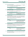
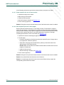
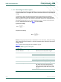
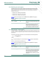
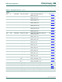
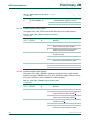
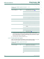
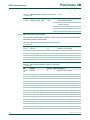
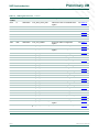
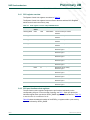
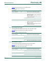
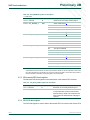
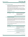
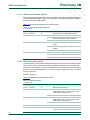
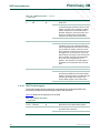
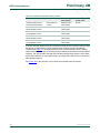
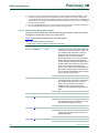
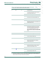
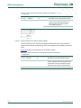
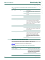
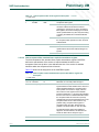
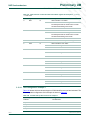
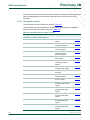
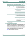
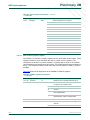
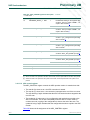
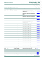
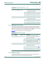
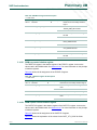
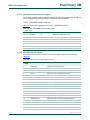
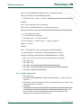
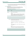
Access Value
Description
i
CLR_STATUS[i]
W
Clears STATUS[i] variable in INT_STATUS
register (set to 0)
FT
FT
A
A
R
R
D
D
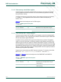
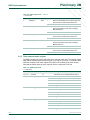
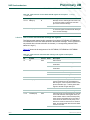
Variable Name
F
FT
FT
A
A
R
R
D
D
D
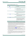
Bit
1
FT
FT
FT
FT
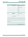
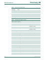
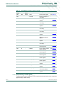
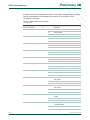
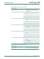
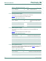
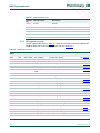
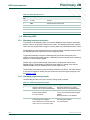
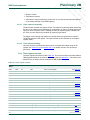
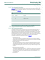
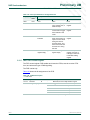
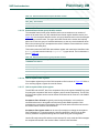
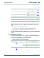
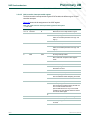
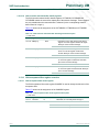
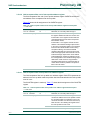
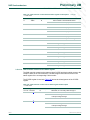
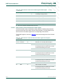
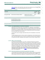
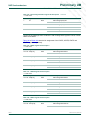
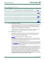
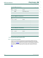
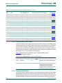
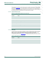
INT_CLR_STATUS register bit description
A
A
A
A
R
R
D
D
D
LPC2917/19 - ARM9 microcontroller with CAN and LIN
Table 8.
FT
FT
FT
FT
FT
Preliminary UM
NXP Semiconductors
D
D
R
A
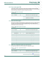
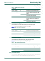
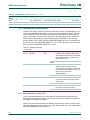
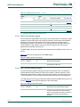
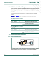
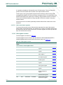
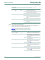
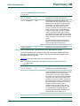
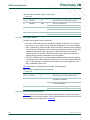
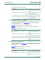
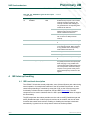
Interrupt set-status register
FT
2.4.2.6
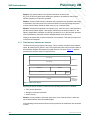
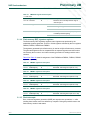
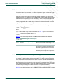
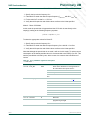
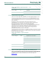
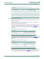
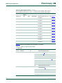
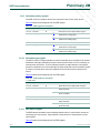
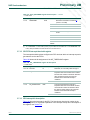
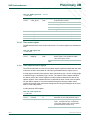
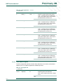
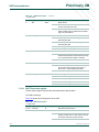
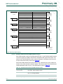
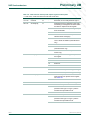
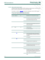
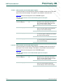
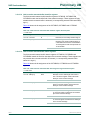
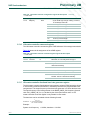
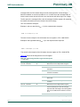
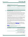
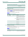
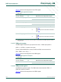
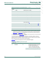
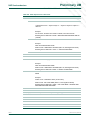
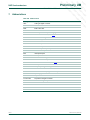
Bit
Variable Name
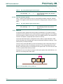
Access Value
Description
i
SET_STATUS[i]
W
Sets STATUS[i] variable in INT_STATUS
register to 1
1
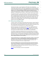
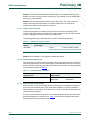
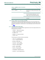
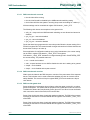
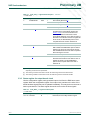
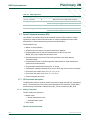
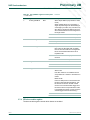
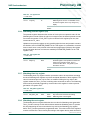
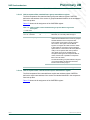
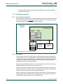
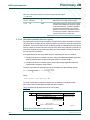
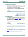
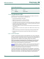
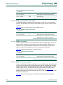
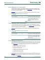
2.4.3 Wake-up
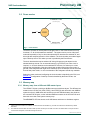
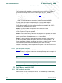
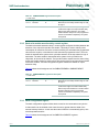
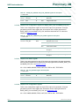
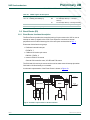
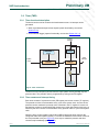
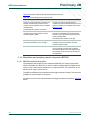
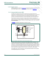
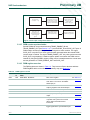
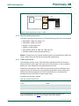
In low-power mode, selected idle clock domains are switched off. The wake-up signal
towards the CGU enables the clock of these domains. A typical application is to configure
all clock domains to switch off. Since the clock of the ARM processor is also switched off,
execution of software is suspended and resumed on wake-up.
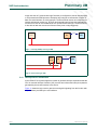
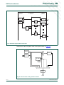
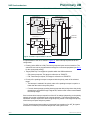
In this case the Event Router is configured to send a wake-up signal towards the CGU
(Clock Generation Unit). Examples are events to indicate the reception of data (e.g. on the
CAN receiver) or external interrupts.
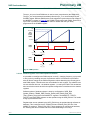
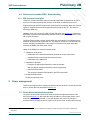
The VIC can be used (IRQ wake-up event or FIQ wake-up event of the Event Router) to
generate a wake-up event on an interrupt occurrence. This is only possible if the clock
domain of the interrupt source is excluded from low-power mode. The VIC does not need
a clock to generate these wake-up events.
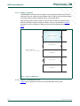
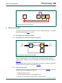
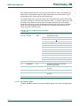
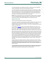
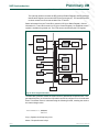
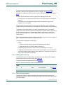
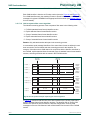
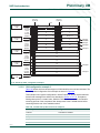
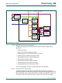
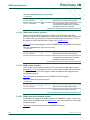
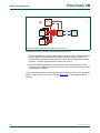
Examples of use are to configure a timer to wake up the system after a defined time, or to
wake up on receiving data via the UART.
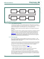
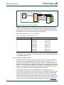
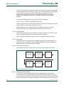
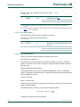
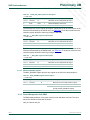
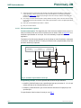
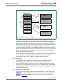
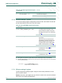
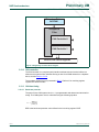
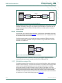
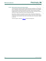
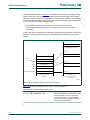
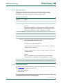
wake-up
UART
CGU
Event
Router
Events
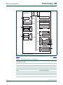
Fig 12. Interrupt (UART) causing a wake-up
UMxxxxx
User manual
© NXP B.V. 2007. All rights reserved.
Rev. 01.02. — 8 November 2007
19 of 263
A
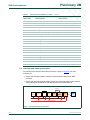
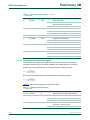
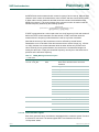
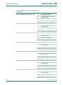
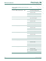
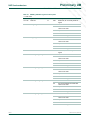
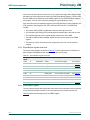
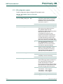
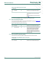
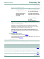
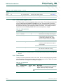
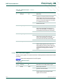
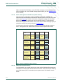
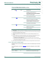
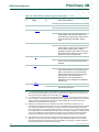
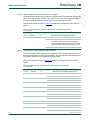
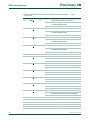
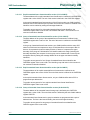
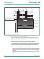
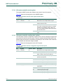
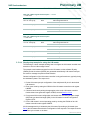
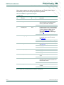
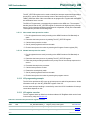
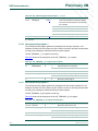
INT_SET_STATUS register bit description
R
Table 9.
D
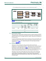
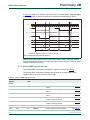
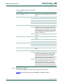
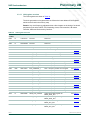
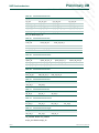
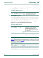
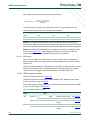
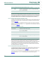
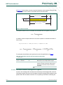
Write ‘1’ actions to this register set one or more STATUS variables in the INT_STATUS
register. This register is write-only and is intended for debug purposes. Writing a ‘0’ has no
effect.