1
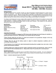
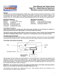
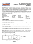
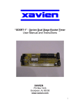
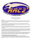
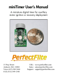
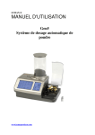
User Manual and Instructions Model WRC² Wireless Remote Control Overview The WRC² Wireless Remote Control System provides two independent high-current FET outputs for hobby rocketry remote control applications. The most common applications of remote control are redundant recovery system deployment or for aerial staging, however the unit is suitable for triggering any type of user-controlled event. The RF communications operate using a 900MHz spread spectrum transmitter in conjunction with a broad band receiver. The communications also employ highly secure digitally encoded data packets which provide reliable, interference-free operation of the unit. This encoding also prevents the need for impounding transmitter units while at an organized launch. Specifications (Receiver) Dimensions: 5.5"L x 3.25" W x 1"H Weight: 2.8 oz. Electrical: 11-14 VDC / 40ma nominal Frequency: 902-928 MHz Environment: 32-120 deg F / 95% RH Specifications (Transmitter) Dimensions: 6" L x 3" W x 2" H Weight: 6.8 oz. Electrical: 3 VDC / DL123A Lithium battery Frequency: 902-928 MHz frequency hopping Environment: 32-120 deg F / 95% RH Handling Precaution These units are sensitive to damage from ESD (electro-static discharge) and should always be handled in a properly grounded environment. ESD damage is not covered under your warranty. Transmitter Operation It is recommended that you first install the battery to activate the transmitter. Remove the top cover of the transmitter housing and insert the battery as shown, noting the polarity of the battery (positive towards top, negative towards bottom). Transmitter Unit Assembly Reset Button Antenna on top of transmitter Note the Battery Orientation! - DL123A + Transmitter PC Board After the battery has been inserted, press the Reset Button on the transmitter board. This ensures the restoration of the transmitter ID code from the unit's non-volatile memory. It is also advised that the battery be checked for adequate voltage level under load. Using a DMM, connect the meter leads to the battery and depress either of the front panel switches. The battery should maintain its 3-volt level. If the battery dips below 2.9 volts or lower, it is a good indication that the battery needs to be replaced. Lithium cells have a sharp degeneration curve and the voltage dip indicates a bad battery. IMPORTANT: Do not operate the unit with a low-voltage transmitter battery as this might cause faulty operation. Always use a fresh battery and load test the transmitter battery prior to use. The transmitter is now ready for use. Replace the front cover. When operations with the unit are finished, you can remove the battery to increase its useful service life. 1 Receiver Operation The Receiver unit has two remote control channels, each having a distinct function. Channel 1 is the primary remote control channel and provides a follower type operation (it follows the Ch. 1 pushbutton on the transmitter). Channel 2 is the secondary channel and provides a "latched" (continuous) output when the Ch. 2 pushbutton is pressed. The latching can be reset by pressing the Latch Reset Switch or simply powering off the receiver. In addition the channel 2 output provides an additional "out of range" function. The receiver and transmitter conduct a regular dialog during operation. When the receiver is operating and it has not received a valid signal from the transmitter for 60 minutes, it will energize the channel 2 output. This feature can be used to activate a homing device or other event if the rocket and receiver unit drift away from the launch area beyond the range of transmitter. As long as the receiver is in range of the active transmitter unit, the channel 2 output will be operate via pushbutton. The line of sight range of the transmitter is 2 miles, so if you are using the "out-of-range" feature, it's best to remove the battery from the transmitter to ensure the operation of this feature. The receiver also features an audible continuity verification feature. When both output channels have good continuity, the receiver will beep 2 times. When just one of the channels have continuity, then only one beep is heard. And of course, when there is no continuity, there is no beeping of the receiver unit. Receiver /Transmitter Testing and Operation The receiver unit can be tested by observing the diagnostic LED's on the RF board located beneath the top interface board assembly. With the receiver power source connected, and NO connections on the respective output terminals, press the channel 1 or channel 2 switch on the transmitter. The #1 or #2 LED's on the RF board will illuminate, depending on which switch was pressed. Important: Always press and hold the transmitter pushbuttons to ensure the complete transmission of a data. There is a slight delay in the communications as the transmitter sends several redundant data packets. Data packets are sent for each ON and OFF transition of the pushbutton. For maximum data throughput and response when triggering two events very closely together, it is advised to PRESS AND HOLD the first event pushbutton, then press and hold the second pushbutton as required by your application. This will prevent the OFF message data packets from being sent which subsequently will increase the event response time. Always be sure to press the reset button after testing the channel 2 output to reset the latch. Do not connect a live igniter or pyro charge to the channel 2 output that is latched on. Wiring and Battery Considerations Ordinarily the receiver power source is used to supply the voltage/current to the igniters, e-matches, or pyro charges. The receiver electronics use high power current-sinking MosFETs capable to 12 amps per output. There is no current limiting on these outputs and they will sink as much current as the output load requires. In situations where a high output current load is required, it's recommended to use separate isolated receiver power and output load power battery systems. This will ensure the receiver battery power source will maintain adequate voltage during the firing of high current outputs. Receiver Board Assembly Channel 1 Output (Squib 1) _ + Channel 2 Output (Squib 2) _ + External User Supplied Switch _ + Battery Input (11-14 VDC) Latch Reset Button TX Programming Button (Factory Only) 2 Important: If the output load draws excessive current from the receiver battery system during firing, this condition could drop the receiver battery voltage to a level below which it can operate reliably. Always adequately size your battery system for adequate load handling capacity and ground test the system prior to committing to flight conditions. Isolated Output Load Battery and Receiver Battery Wiring Isolated Battery wiring is recommended only for high current output load applications. To wire isolated power for the output loads, connect the plus (+) lead of the output load battery system through an external switch to one side of the igniter or e-match, and the other lead of the igniter or e-match to the (-) terminal of the channel 1 or channel 2 output terminals. Connect the negative lead of the output load battery to the negative (-) terminal of the receiver battery input. Ensure the Output Load Battery voltage is at least 1/2 the Receiver battery voltage so it can operate the continuity testing circuitry. Important: When arming the unit, ALWAYS turn on the RECEIVER POWER FIRST, followed by the IGNITER POWER SWITCH. Failure to arm the unit in this sequence may fire an igniter. Isolated Battery Wiring Diagram External User Supplied Switch (Igniter Power) Igniter 1 _ + Igniter 2 _ + External User Supplied Switch (Receiver Power) _ + + + - Receiver Battery (11-14 VDC) - Output Load Battery (6-14 VDC) E-matches and Ejection Charges The topic of e-matches and ejection charges is often overlooked and not given a proper evaluation. The ejection charge is as critical a component as the electronics. Improper selection or application of e-matches can result in failure of the recovery system and total loss of the rocket. The following text will make some very specific recommendations which you should seriously consider when selecting, constructing, and ultimately flying with electronic deployment systems. Important: Always ground test the type of e-match or igniter you'll be using under actual flight conditions prior to committing to flight. Improper selection of an e-match or igniter will result in a malfunction. Always use an e-match or igniter that is suited for the firing conditions of the WRC² unit Always check your e-match, igniter, or flash bulb devices for continuity and proper resistance prior to using them under testing or actual flight conditions. Selecting an adequate E-match The WRC² has been tested and flown with several commercially available e-matches. It has also been successfully tested and flown with AG-1 flashbulbs, and custom made .003" nichrome bridgewire ejection charges. This, however, is a just a small sampling compared to what is commercially available.. Refer to Table 1 for commercial e-match suppliers for the WRC². 3 Table 1 - Recommended E-match suppliers Daveyfire Inc. 7311 Greenhaven Dr, Suite 100 Sacramento, CA 95831-3572 Tel: 916.391.2674 Fax: 916.391.2783 Model Daveyfire 28B Daveyfire 28BR Daveyfire 28F Oxral Resistance 1.6 ± 0.3 ohms 1.6 ± 0.3 ohms 1.6 ± 0.3 ohms 2 ohms (nominal) OXRAL Inc. (Luna-Tech) PO Box 160 Owens Cross Roads, AL 35763 Tel: 205.725.4226 Fax: 205.725.4811 Test Current 20 ma (0.020 amp) max 20 ma (0.020 amp) max 20 ma (0.020 amp) max 25 ma (0.025 amp) max Firing Current 370 ma (0.37 amps) min 370 ma (0.37 amps) min 1.00 amp min 500 ma (0.5 amp) min Wire Color White Orange Black Red/Blue Ejection charges The ejection charge consists of a small quantity of black powder which when ignited produces enough gas pressure to expel the recovery system from the body of the rocket. You can either make your own ejection charges or purchase commercially available ejection charge systems. Robby's Rockets provides two ejection charge systems, one single use, the other a reloadable system. Refer to Table 2 for more information. Table 2 - Commercial Ejection Charge suppliers Disposable Ejection Charges Robby's Rockets P.O. Box 171 10 prewired AG-1 bulbs in cardboard Elkhart, IN 46515 tubes, 1 gram measuring cup, end caps 219.679.4143 and mandrel L.E.S. Kits (Loadable Ejection System) Reusable aluminum charge holder, 10 prewired AG-1 bulbs, 1 gram measuring cup, end caps and mandrel There are several methods for constructing your own ejection charges. First you'll need to acquire some black powder locally. It is recommended that you use FFFF (4F) grade, however FFF (3F) powder can be used. Another commercially available powder is called Pyrodex, which should not be substituted for black powder. The following formula represents a general rule of thumb for calculating the required amount of black powder for a given airframe. Factors such as a tight-fitting nose cone or coupler, as well as a tight-fitting parachute or streamer, can affect the performance of an ejection charge. It's always better to have a little extra black powder, as not enough could possibly result in deployment failure. Black Powder (grams) = Compartment Diameter (inches) X Compartment Diameter (inches) X Compartment Length (inches) X .006 Unless you've got a reloading scale, the easiest method to measure black powder is to purchase a set of black powder measuring cups from your local firearms dealer. Quick and Easy Ejection Charge One easy method for constructing charges is to use aluminum foil and some masking tape. Start with a small square of aluminum foil (about 4" to 5" square). Form a small "thimble" by molding the foil over your index finger. Next measure in the necessary amount of black powder. Insert your e-match or flashbulb into the black powder. IMPORTANT: Be sure that the leads to the flashbulb or e-match are COMPLETELY INSULATED, otherwise the leads could short out on the foil, causing the charge to fail. Finish the charge by compressing the remainder of the foil around the black powder and e-match/flash-bulb. Seal the end with a wrap or two of masking tape. Reusable ejection charge system Another method is to construct a set of reusable canisters from 1/2" launch lug tubing and 1/2" wooden dowel. First cut a small length of launch lug tubing. The length of the tubing will depend on the amount of black powder necessary and what you're using to ignite it. A flashbulb requires much more real estate than an e-match. After properly sizing the tubing, take the 1/2" dowel and cut a thin slice (about 1/8" thick) off the end. Take this slice of dowel and epoxy it into one 4 end of your tubing. When the epoxy has cured, drill a small hole through the slice of dowel. The hole diameter will depend on the size of the wire leads you'll be using. The canister is now complete. Place the flashbulb or e-match into the canister, pulling the wire leads through the small hole. Seal this hole with a hot glue gun or silicone. Fill the canister with the necessary amount of black powder. Gently tamp the black powder against the bulb or e-match with a small length of the 1/2" dowel. Next, tamp in a small piece of tissue paper, then seal the canister by melting some candle wax over the tissue. Be careful with the open flame of the candle around the black powder. After firing the charge, the wire leads and bulb/match remains can be removed and the canister reloaded for another use. A convenient means of holding these charge canisters is to use a 1/2" CPVC end cap with a small hole drilled along the bottom for the wire leads. Fasten the end cap securely on a bulkhead surface with a screw. Place a few wraps of masking tape around the outside of the canister, pull the wire leads through the hole and you'll get a very snug fit in the CPVC end cap. Reusable ejection charge system Black powder Tissue/wax plug Flashbulb or e-match Dowel slice with hole Wire leads Glue or Silicone seal Hole for wire leads CPVC end cap Launch Day Now that you have methodically designed and built your rocket and its recovery system, it's time to fly. There's usually lots of activity on a launch day with other fliers and other rocket flights. It's best to prepare your rocket carefully and not to bypass any critical steps. The following list is a guideline of the necessary steps you should take in the preparation of your WRC². At the prep table • Load test the battery • Check continuity and resistance of the ejection charges • Mount and secure the electronics in the payload section • Make final wiring connections to the electronics • Prepare and pack the recovery components (parachutes, wadding) • Assemble the rocket and check all deployment coupling junctions ensuring a snug and adequate fit • Arm the electronics and verify ejection charge continuity • Disarm the electronics, prepare and load the rocket motor At the Pad • Place the rocket on the launch rod or rail • Insert the igniter in your rocket motor • Verify continuity of the motor igniter (if possible) • Arm the electronics and re-verify ejection charge continuity • Snap a few photos, then RELISH IN THE CULMINATION OF ALL YOUR WORK AND PREPARATION 5 Product Warranty Missile Works Corporation has exercised reasonable care in the design and manufacture of this product and warrants the original purchaser that the WRC² Wireless Remote Control System is free of defects and that will operate at a satisfactory level of performance for a period of one year from the original date of purchase. If the system fails to operate as specified, then return the unit (or units) within the warranty period for repair or replacement (at our discretion). The system must be returned by the original purchaser, and be free of modification or any other physical damage which renders the system inoperable. Upon repair of replacement of the unit, Missile Works Corporation will return the unit postage paid, to the original purchaser. Product Disclaimer and Limit of Liability Because the use and application of this equipment are beyond our control, the purchaser or user agrees to hold harmless Missile Works Corporation and their agents from any and all claims, demands, actions, debts, liabilities, judgements, costs, and attorney fees arising out of, claimed on account of, or in any manner predicated upon loss or damage to property of, or injuries to or the death of any and all persons arising out of the use this equipment. Due to the nature of electronic devices, the application and environments for those devices, the possibility of failure can never be totally ruled out. It is the responsibility of the purchaser or user of this equipment to properly test and simulate the actual conditions under which the device is intended to be used to ensure the highest degree of reliability and success. Rules to live and fly by 1. Before you use the WRC² Remote Control System, make sure you have read and understand all the instructions, operations, and warnings contained herein. 2. Do not alter the system in any way, as this voids the warranty and could render the system inoperable or unreliable. 3. Always fly within the guidelines established by either the National Association of Rocketry or the Tripoli Rocketry Association whenever you participate in hobby rocketry activities. MISSILE WORKS CORPORATION P.O. Box 740714 Arvada CO 80006-0714 Tel: 303.426.1462 Fax: 303.426.1428 On the World Wide Web @ www.missileworks.com Copyright 1998-99 by Missile Works Corporation. All rights reserved 6