1
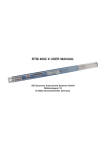
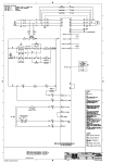
ARGOS Surface Beacon
ASB and ASB X
User Manual
Version 1.3
February 2008
SiS Sensoren Instrumente Systeme GmbH
Mühlenkoppel 12
24222 Schwentinental
Germany
http://www.sis-germany.com
Contents
1. General Information ..............................................................................................2
1.1 Description ........................................................................................................2
1.2 Switch Mode Power Supply Option.................................................................2
2. Operating Instructions ..........................................................................................3
2.1 Choosing Batteries for your Application ........................................................3
2.2 Opening the Housing........................................................................................3
2.3 Insertion of Batteries ........................................................................................3
2.4 Replacement of Moisture Absorbent ..............................................................4
3. Principle of Operation ...........................................................................................4
3.1 MBM Operation .................................................................................................4
3.3 Admission to the Argos System......................................................................4
4. Appendix ................................................................................................................4
4.1 Technical Specification ....................................................................................4
4.2 Warranty and Support ......................................................................................5
List of Figures
Figure 1 ASB ..............................................................................................................2
1
1. General Information
1.1 Description
The ASB (X) consists of a DELRIN tube closed by end caps.
711
681
100
23
SN
plate
Delrin
cap
Internal
antenna
Delrin tube
Delrin cap
Scale
Date
Clrk
Chkd
Norm
Name
02.03.94 Ar
Sensoren
Instrumente
Systeme GmbH
Rev Modification
Date
Name
ASB
Sheet
of
1
1
Figure 1 ASB
Inside the housing is a battery holder for two bundles of 5 batteries each in series, the PTT
and the antenna. The batteries power the transmitter (PTT) directly or via an optional switch
mode power supply (X Option).
The ASB (X) is for surface applications. If you need a SMM for deep sea moorings please
use the SMM 2000 or SMM 6000 series, or for shallow water up to 500 m depths, use the
SMM 500.
1.2 Switch Mode Power Supply Option
Instruments marked with an X have the extended battery option. They can be used with a
wider selection of battery types. The battery voltage is converted to the right level by a switch
mode power converter. For instruments without the X-option, the batteries directly power the
transmitter. The X-option may be installed to all systems later.
2
2. Operating Instructions
2.1 Choosing Batteries for your Application
The cell voltage has to be between 2.2 V and 5.2 V. For instruments with the X-option the
cell voltage has to be between 0.8 V and 5.2 V allowing the usage of alkaline batteries or
nickel cadmium accumulators as well. For long term moorings in cold environment we
recommend to use high quality Lithium cells.
The batteries must be able to source 350 mA continuous current and 1700 mA pulse current.
So you should use a battery type which has good efficiency with high currents. This applies
especially to Lithium and Lithium Thionyl Chloride Batteries.
For calculation of battery lifetime use the average power consumption. Divide the energy
content of the 10 batteries by the mean power consumption (100 mW) of the beacon. The
table shows typical life times for different battery types:
Temperature
20 °C
0 °C
-30 °C
Lithium battery:
Alkaline battery:
NC battery:
Lithium
150 days
150 days
140 days
Alkaline
60 days
50 days
not applicable
NC
30 days
28 days
not applicable
Silberkraft Eternacell, Lithium-SO2, Size D, Capacity 10 Ah
Philips LR20, Green Alkaline, Size D, Capacity 13.2 Ah
Panasonic 4000N, NC, Size D, Capacity 4 Ah
For instruments without the X option use the Lithium values only!
2.2 Opening the Housing
You open the housing by removing the lower end cap. The cap is fastened by two hexagon
socket screws. For opening please screw clockwise thereby turning in the screw into the cap.
This paradox solution - screwing in for opening and screwing out for fastening - has the
advantage that you won't lose the small screws. When the instrument is opened, screws and
end cap build one unit. You then may pull out the cap. When fastening the cap after closing,
please note to screw the screws not too tight to avoid stronger stress to the DELRIN main
housing.
The inner part is fastened at the main tube.
2.3 Insertion of Batteries
Don't open the housing by removing the upper cap. Open the housing by removing the lower
cap. Put the instrument upside down on the floor and pull out the end cap.
You will now find a PVC disc, take it out and you will see two tubing in a PVC block and one
contact pin. Put 5 pieces D type batteries into each tube, oriented with the minus terminal in
direction of the antenna.
3
If you want the instrument to operate after insertion of batteries close the housing by
insertion of the end cap.
In case you only want to insert batteries but later want to operate, please place the PVC disk
for isolation between batteries and cap.
2.4 Replacement of Moisture Absorbent
The printed circuit boards are protected by coating, but condensation of humidity should be
avoided. When leaving the factory, the instrument is filled with dry argon gas and a small
pack with moisture absorbent is placed in a slot between the battery holder and the at the
lower end. We recommend filling with dry gas or replace the moisture absorbent after every
opening of the housing. Normally together with battery replacement. With the instrument we
deliver some packs with moisture absorbent sealed in a plastic bag and put in a tin.
3. Principle of Operation
3.1 MBM Operation
CLS Service Argos has developed a special service for monitoring the status of the moorings
(MBM, Moored Buoy Monitoring). An alarm is generated if the buoy goes adrift. A warning
that the watch circle is left will be send to the user by email or fax. A warning is also
generated if no signal is received from the beacon. Users always may access data on-line
(e.g. via Telnet or Web).
3.3 Admission to the Argos System
The user must fill out some forms and forward it to the Argos User Office:
• Argos System Use Agreement
• Service Contract/Order Form
Please see the Argos documentation for detailed information.
4. Appendix
4.1 Technical Specification
Water proof
Dimensions (l x d)
Mass without batteries
Displacement
Power Supply
Battery Types without option X
Battery Types with option X
10 m
711 x 100 mm
6.7 kg
5.6 dm3
5 or 10 pcs. D cells resp.
Lithium or Lithium Thionyl Chloride (1)
NC, Alkaline, Lithium or Lithium Thionyl
Chloride (1)
2.2 V - 5.2 V
0.8 V - 5.2 V
1700 mA
100 mW
up to 6 months
3 or 6 months resp.
Serpe IESM
Elta / CEIS
PTT 07
UHF 88 or HAL2
33 dBm (2 W)
33 dBm (2 W)
32 bits
32 bits
90 seconds
90 seconds
401.650 MHz
401.650 MHz (UHF88)
Battery cell voltage (without option X)
Battery cell voltage (with option X)
Peak supply current
Average power consumption
Mooring life
Transmission life with Lithium cells
Transmitter manufacturer (2)
Transmitter model (2)
Output power
Message Length (3)
Repetition rate (4)
Transmit frequency (5)
4
401.620 MHz
401.630 MHz (HAL2)
Notes:
1. The used batteries must be able to source 350 mA continuous current and 1700 mA pulse
current. Some low current types of Lithium Thionyl Chloride batteries can’t be used.
2. There are three transmitter models used with the ASB. Instruments manufactured from
2003 to 2006 are equipped with the Serpe IESM PTT 07 model, those made since 2006 are
equipped with the Elta HAL2 model while older instruments use the Elta / CEIS UHF 88
model.
3. The ASB did not send any user data. Therefore, the message length is set to the minimum
value of 32 bits. With Elta HAL2 transmitters, a prefix byte (typ. 25 hex, with 20-bit ID only),
temperature (°C), supply voltage (mV / 64) and power indication (mV / 4) are send.
4. The default repetition rate is 90 seconds (recommended by Argos). Other rates (e.g. 60
seconds) can be programmed upon request.
5. With Elta HAL2 transmitters, the transmit frequency is programmed to 401.630 MHz
according to the Argos recommendations. With UHF 88 transmitters, the frequency is fixed at
401.650 MHz. The transmit frequency of PTT 07 is set by the manufacturer.
4.2 Warranty and Support
SiS warrants this instrument to the original purchaser to be free of defects in material or
manufacturing for a period of two years. Liability is limited to repair or replacement of the
defective part which will be done without charge if the instrument is returned to our factory
prepaid. This warranty does not apply to instruments subjected to misuse or tampering. No
responsibility or warranty for consequential damage is included in the sale of this instrument.
SiS - Sensoren Instrumente Systeme GmbH
Mühlenkoppel 12, D-24222 Schwentinental, Germany
Tel.: +49-431-79972-0
Fax: +49-431-79972-11
Email: [email protected]
WWW: http://www.sis-germany.com
5