1
Particulars, Advanced Measurement Systems
Data acqusition software user manual
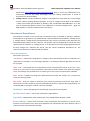
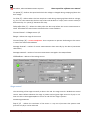
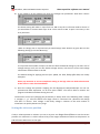
6.) If you intend to do the voltage scan enter the voltage scan parameters. How does it work?
The above setting will make 11 steps from 0 to 100 in step of 10 V if linear mode is chosen. If
you would like to continue with steps of 20 V from 120 V to 500 V open a new entry in the
array and enter
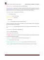
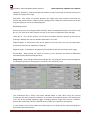
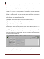
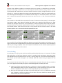
When no voltage scan is required and you would simply want detector at given bias use the
following setting (in this case 80 V only)
It is important that number of steps is 0 and start level the desired voltage. If you don’t care of
voltage settings at all you can also disable voltage sources, but then no current and voltage
information will be written to the file.
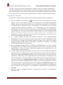
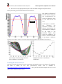
The default setting for applying the bias (Inc. speed, Inc. bias, Delay after bias) are usually
adequate.
Please pay attention to current compliance setting as too high value can lead to destruction
of the sensor in case of the breakdown.
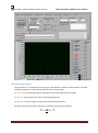
7.) Once the voltage and position stepping has be determined, DRS/oscilloscope set one can
proceed with data acquisition. To do than press START. You will be able to monitor the
progress and taken waveforms during the scan.
The direction of the scan (changing the parameters) is always done in the following order: voltage
1, voltage 2, z, y,x . After the whole scan range is done in x direction the y-direction will change
and after it is done z then voltage 2 and finally voltage 1. Beware as the total number of
waveforms can quickly become very large.
Setting the reference position
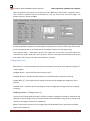
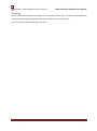
If only a relative position is relevant you can at any time use Stage Control/Reset to set the current
position as a reference ie. 0. All the moves of any of the stages will be done relative to this position. So
100 will mean 100 microns to the right.
Version 1.2, September 2014
Page 10