1
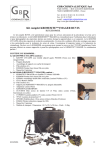
No. KSS60 Copyright© 2011 by SIRCHIE, Youngsville, NC 27596 USA All Rights Reserved. MA04-414ENG-REV10 Table of Contents Introduction...................................................................................................................................3 Specifications and Features.........................................................................................................4 Using The Imager/Initial Setup.....................................................................................................6 Operating Standard UV Light Sources.........................................................................................7 The SirchPod® Copy Stand.....................................................................................................8 Operating The Laser Pointer........................................................................................................9 Canvassing the Crime Scene.....................................................................................................10 Use of the Black Talon Stabilizer (U.S. Patent No. 7,050,715)..................................................................... 11 Conventional & Digital Photography..................................................................................... 12-13 KRIMESITE™ IMAGER Setup for Film and Digital Photography..............................................14 Connecting A Camera to the KRIMESITE™ IMAGER (Digital & Conventional)........................14 Using the Camera Coupler.........................................................................................................15 Camera Relay Lens Adapter......................................................................................................16 Locate Valuable Trace DNA with the KRIMESITE™ IMAGER...................................................17 Visible Compensating Luminol & RUVIS Filter...........................................................................18 FAQ’s..........................................................................................................................................19 Maintenance...............................................................................................................................20 Safety Information......................................................................................................................20 Addendum..................................................................................................................................21 RUVIS Accessory Products.................................................................................................. 22-23 Kit Information............................................................................................................................24 Limited Warranty........................................................................................................................24 SIRCHIE ® 100 Hunter Place, Youngsville, NC 27596 USA Phone: (919) 554-2244 • (800) 356-7311 Fax: (919) 554-2266 • (800) 899-8181 Email: [email protected] • Website: www.sirchie.com 2 MA04-414ENG-REV10 Introduction Function The SIRCHIE® KRIMESITE™ IMAGER is an image intensified device which locates untreated fingerprints and other evidence of forensic interest on non-porous surfaces by the Reflected UV technique. No treatment with powders or chemicals is necessary. Use of the Imager greatly enhances results obtained by cyanoacrylate fuming. The KRIMESITE™ IMAGER is most effective on non-porous surfaces, but can detect fresh prints on some porous surfaces. Background We see, or are able to image an object either because it emits light or because it reflects light incident upon it. Objects that reflect light do so in a characteristic manner: They may reflect strongly or weakly, specularly or diffusely, and they may reflect some colors and not others. For example, the sunlight impinging on a healthy leaf is made up of all visible colors. The leaf will absorb most of those colors, but will strongly reflect a particular range of colors back to our eyes, which is, of course, why it appears green to us. Other objects reflect other colors. It is differences in the reflective properties of materials that allow us to distinguish objects that do not emit their own light. Such differences in reflectance extend to most materials and to most wavelengths of radiation. Our eyes easily detect subtle differences in reflectance in the visible light wavelengths. But there are wavelengths that our eyes do not see. Instruments designed to see in those wavelengths show us the world in a new perspective. Detection and enhancement of fingerprints by reflection of short wavelength UV light has long been reported in Forensic Journals. In brief, differences in reflectance exist between a fingerprint and the surface on which it is located; although they may be slight, instruments can be designed to amplify and enhance those differences. The SIRCHIE® KRIMESITE™ IMAGER is one of a new generation of such instruments. It utilizes a micro-channel plate-based image intensifier in conjunction with optics specifically designed to image short wavelength (ultraviolet) light and a series of special bandpass filters to allow you to see untreated fingerprints even in daylight. No. KSS60 KRIMESITE™ IMAGER Direct View Kit Contents: 1-KRIMESITE™ IMAGER w/KSS100b 60mm UV Lens 1-KSS9696 Class IIIa Laser Pointer w/batteries 1-KSS8010 Dual Filter Slide Assembly (Luminol/Visible and UV) 1-CR123 Lithium Battery 12-AA Alkaline Batteries 1-KRIMESITE™ IMAGER Steady Rest w/Removable Pistol Grip 1-58mm Camera Adapter 1-KSS9200 SIRCHPOD® Copy Stand 1-CUV100TS UV Mini Light Source (4-watt 254nm shortwave, battery operated) 1-UVP600ST UV Panther AC/DC Shortwave Light, 254nm 2-797GV UV Protection Spectacles 1-EPS30KS Photo Evidence Scales (white on black, 10-pk) 1-KSS684 Pkg. Arrow Designators (100 count) 1-Operator’s Manual 1-Carrying Case, Custom- fitted, moisture resistant; Dimensions: 21"W x 9"H x 16.5"D (53.3cm x 22.9cm x 41.9cm); Weight: 18.6 lbs. (8.4kg) 3 MA04-414ENG-REV10 Principles of Ultraviolet Imaging Visualization of Latent Prints with Ultraviolet Illumination Depends on Several Factors… Angle of incidence of the ultraviolet rays Distance of ultraviolet source from target area Target area absorption quality Relative angle of optical system to target Distance of system from target RUVIS INCIDENT UV Diffuse Reflection from Fingerprint Residues Barrier Filter Objective Lens Image Intensifier Eye Eyepiece Specular Reflection from Non-Porous Surface Reflected UV Diminished by Diffused Reflection from Fingerprint Residues REFLECTED UV 4 MA04-414ENG-REV10 Specifications and Features VISIBLE COMPENSATING LUMINOL AND RUVIS FILTER RUBBER EYECUP APERTURE RING EYEPIECE FOCUSING RING FOCUSING BARREL USER-FACING CONTROL PANEL AND BATTERY ACCESS CONTROL PANEL • Rotary Control, Power ON/OFF • Visual Indicator: Green LED, Image Intensifier ON • Battery Access: Threaded Cap, spring loaded USER-FACING CONTROL PANEL Removable pistol grip LASER POINTER TOGGLE ON/ OFF SWITCH 6” wrist lanyard KRIMESITE™ IMAGER Steady Rest Attachment BATTERY COMPARTMENT Optics The SIRCHIE® KSS100b 60mm f/3.5 lens has been designed as an integral component of the KRIMESITE™ IMAGER. The KSS100b lens is an Ultraviolet (UV) compound lens designed specifically for the detection of fingerprints using UV light with optimum performance in the UV waveband of 230nm to 290nm. • • • • • • • • • • Focal Length: 60mm Aperture: f/3.5-f/32 Image Format: 17.5mm dia. Object Distances: Close-up to Infinity Mount: C-Mount Lens Construction: 4 elements, all quartz Geometric Distortion: <0.1% in corners Vignetting: <22% in corners Mechanical Length: 102mm to 160mm Mechanical Diameter: Max. 61mm The KSS100b lens is specifically optimized for UV fingerprint visualization, while also operating in the visible waveband for visible light viewing. VISIBLE/LUMINOL & RUVIS FILTERs • Shortwave Bandpass: 254nm peak with 25nm (full width at half maximum) bandwidth typical • Fast Filter Selection: Each sliding filter assembly carries one UV filter window and one clear window for the visible waveband. • Luminol Enhancement Filter: Sliding filter assembly contains both UV and Luminol enhancement filters. UV Image Intensifier Tube • GEN II, double proximity focused, 18mm • Built-in over brightness protection (tube automatically limits gain from bright light sources) • >/=40 Lp/mm typical • P22 Phosphor • S20 Photocathode • Input Window: Quartz • Image Inversion: None Laser pointer • Wavelength: 650nm • Aperture Output Power: 2.1 - 3.0 mw • Operating Voltage: 3.0V DC, internal •Control: Push-button; Momentary ON Imager • Material: Extruded Aluminum, 6061-T6 alloy • Finish: Black Anodized, Vinyl covered selected areas • Objective Mount: C-mount •Configurable Steady Rest for safe instrument support during periods of non use • Removable contoured foam covered pistol grip • 6" Wrist Lanyard, removable • Eyepiece, with removable rubber eyecup - Adjustable focus - 25mm eye relief BATTERY • Lithium, 3.0V DC, type CR123 UV Lamps Supplied/ Shortwave • UVP600ST UV Panther AC/DC Shortwave Light, 254nm • CUV100TS UV Mini Light Source (4-watt shortwave, battery operated) 5 MA04-414ENG-REV10 Using The Imager USING THE IMAGER/Initial Setup Installing the Battery To insert the CR123 3V Lithium Battery into the KRIMESITE™ IMAGER, remove the battery compartment cover (Fig. 1) by turning it counterclockwise. Insert the battery into the compartment with positive (+) terminal toward the inside (Figure 2). Replace the battery compartment cover by turning it clockwise. Do not over tighten. Check to see if battery is installed correctly by rotating the Fingertip Control Knob clockwise to the ON position. FIGURE 1—Battery Access The green LED should illuminate (if not, check battery polarity). NOTE: If the unit is to be stored for extended periods, remove the battery. FIGURE 2 Installing the Luminol/Visible and RUVIS Filters FIGURE 3—Always insert the sliding filter from the left side of the unit as shown, with label facing the eyepiece. Both the Luminol/Visible and UV Filters are contained in the KSS8010 Dual Slide Filter. Machined detents provide positive and fast switching from RUVIS to Visible Viewing Modes. Insert the sliding filter array in from the left side of the Imager and position the direct view window directly behind the 60mm UV lens (Fig. 3). The Direct View Luminol/ Visible Filter is clear and the RUVIS Filter is mirrored or opaque (Fig. 4). Once the focus has been set for either waveband, the lens requires minimal refocusing when switching between modes. These filters are fashioned from glass and should be handled accordingly. When cleaning the filters, use approved lens cleaner fluid FIGURE 4—RUVIS Filter (mirrored window, left); and lens cleaning tissues. Visible/Luminol Filter (clear window, right). Focusing the Eyepiece To properly focus the eyepiece, hold the KRIMESITE™ IMAGER in your hand with the lens facing out and place the filter in the visible position. Proceed as follows: 1. Point the Imager at a surface (preferably a brightly lit area) and look into the eyepiece. 2. Rotate the focus-barrel of the UV lens clockwise, as far as it will turn (Figure 5). This should blur the image you are looking at. 3. Open the aperture of the UV lens all the way to the f/3.5 position (Figure 6). FIGURE 5 4. Slightly rotate the eyepiece focus ring as shown below in Figure 7 FIGURE 6 until you can discern the faint hexagonal (honeycomb shaped) pattern in the viewing screen (see Figure 8). Once this pattern can be seen the eyepiece is focused correctly and the KRIMESITE™ IMAGER is ready for use. EYEPIECE FOCUS RING FIGURE 7 6 Note: Focusing the eyepiece only needs to be accomplished at the beginning of each use, but may vary for individual users. FIGURE 8—Example of the faint hexagonal pattern seen when the eyepiece is best focused (pattern has been emphasized—image enhanced and magnified for easy viewing in this manual). MA04-414ENG-REV10 Operating Standard UV Light Sources SPECIAL PRECAUTION: Avoid the use of shortwave UV light (254nm) in the presence of visible bloodstains if subsequent DNA analysis is a consideration. Collect blood samples prior to shortwave UV light exposure. Warning: Prior to operating any shortwave UV light, be sure to observe the UV exposure precautions mentioned in the safety section of this manual. Never use these lights without wearing protective eyewear. The UV Panther Portable AC/DC Shortwave Light The UVP600ST UV Panther Light was designed to fill the need for an allpurpose, portable, 6-watt, shortwave UV light source (254nm) and is the standard light source supplied with the Krimesite™ Imager. It can be easily used in the field or laboratory and features a tripod mount. This mount easily connects to the KSS9200 SIRCHPOD® (see left inset) or the optional BM6009 Professional Duty Tripod for hands-free operation. Dual Power Supply This light utilizes a dual power supply: AC Operation—120V AC or 220V AC Power Adapter (included); DC Operation—8 AA (nonrechargeable) Alkaline Batteries. DC Operation—For DC operation, install the eight (8) AA Alkaline Batteries provided into the battery magazine located inside the compartment on the back of the unit (Fig. 1). Access is gained by removing the two thumb screws that secure the protective metal plate (be certain to observe polarity). FIGURE 1 FIGURE 2 AC Operation—connect the supplied AC Adapter to the unit through the side panel jack (Fig. 2) and plug into any convenient 110V or 220V AC outlet accordingly—this disconnects the AA batteries and provides rectified DC voltage to the lamp. Turn the unit on with the On/Off Switch mounted on top of the housing. A green LED (Light Emitting Diode) power indicator will flash intermittently. Be certain to wear proper UV protective eye wear when the light is in use. CUV100TS UV Mini Light Source The CUV100TS (included with your KRIMESITE™ IMAGER kit) was specifically designed for use with the Imager. It serves as a fully portable, battery-operated shortwave UV light source for field and lab use. The unit provides shortwave UV light at an approximate frequency of 254nm and is powered by four AA alkaline batteries (included). The light is equipped with one 4-watt germicidal bulb which is protected by a brushed nickeloid shield. NOTE: See instructions supplied with unit for operation. The Puissant 30-Watt Shortwave UV Light The SKSUV30 Puissant Lamp provides high intensity shortwave (254nm) illumination when searching large areas for latent prints. Two 15-watt germicidal lamps provide a full 30 watts of shortwave light. The lamp is equipped with a shortwave filter that blocks visible light. A sturdy base provides self-support when hands-free operation is needed. The SKSUV30 features dual voltage capability for either 110V or 220V AC operation. The Puissant was designed for use in the crime laboratory and at crime scenes where a more powerful shortwave UV source is needed. It is especially useful when used as a companion to the KRIMESITE™ IMAGER. No. SKSUV30 shown in carrying case. 7 MA04-414ENG-REV10 Using the Puissant Light The SKSUV30 Lamp operates from a standard AC power source. A sensor built into the lamp circuitry detects whether the power source is 120V AC or 220V AC and automatically switches to the proper power configuration (220V AC cord adapter not included). A single, rocker-type ON/OFF switch controls the bulbs. After being certain that all safety precautions have been taken, and that all those present are wearing the necessary protective gear, plug the power cord into the nearest power outlet, direct the lamp toward the area to be searched, and switch it on. Visible light may be seen when the lamp is on, but do not look directly into the lamp. The lamp may be carried around the area being searched using the carrying handle, or it may be placed on a flat, level surface. To avoid unnecessary exposure to the UV radiation, all of those present should remain behind the light source and wear appropriate protective clothing. POWER ON/OFF SWITCH UV FILTER FUSE POWER CORD RECEPTACLE the SIRCHPOD® Copy Stand The KSS9200 SIRCHPOD® Copy Stand was designed specifically for laboratory and field use when photographing latent fingerprints and other forms of physical evidence. The device is supplied as a companion to the SIRCHIE® KrimeSite™ Imager system. The SIRCHPOD® copy stand accommodates any device equipped with a tripod mount. The copy stand is equipped with adjustable legs and a swivel camera mount permitting a range of up to 180° degrees. It is configured in such a manner as to allow photographs to be taken directly above an object without the support legs encroaching into the photo. Assembly (not shown): Installing the SIRCHPOD® legs is the only assembly required. Screw each of the legs into the pre-drilled holes in the copy stand base. With the legs fully retracted, the base of the SirchPod® is approximately 9.75" tall and fully extended is about 23" tall. Camera Mounting Shoe Mounting: 1. The camera swivel head is equipped with a cameramounting shoe. Remove the shoe from the unit by moving the release lever. The small brass lever next to the release lever is a locking device. It may be necessary to move the lock before the shoe can be detached, see Figure 1. 2. The bottom side of the camera shoe is embossed with an arrow ( ) with the word “LENS”. Mount the shoe on the bottom of the KRIMESITE™ IMAGER handle as shown in Figure 2 with the arrow pointing toward the lens. Tighten the camera mounting screw. Locking Lever Swivel Head Adjusting Screw (Partially Shown) Release Lever FIGURE 1—Swivel Head Assembly 8 MA04-414ENG-REV10 FIGURE 2—Shoe Mounting 3. Place the Imager and shoe assembly back into the SIRCHPOD® mount and lock it in place using the brass lever. Position the Imager at the desired angle by loosening the large adjusting screw (the 60mm UV lens should be pointing down towards the center opening of the stand as shown in Figure 3). The copy stand is now assembled and ready for use. FIGURE 3 Operating the Laser Pointer The Class IIIa Laser Pointer is mounted to the KRIMESITE™ IMAGER by snapping it into the mounting cradle located on the left side of the Imager (Fig. 1). The Activation Button should be facing away from the unit. It is powered by two type L1154 batteries. To operate the Laser Pointer, simply press and hold the Activation Button down as shown in Figure 2 below. ACTIVATION BUTTON FIGURE 1—Snap the Laser Pointer into the mounding cradle located on the left side of the Imager. FIGURE 2—The Laser Pointer is operated by pressing and holding the Activation Button down. NOTE: See the technical information sheet supplied with the Laser Pointer for detailed operation and battery replacement. NO. KSS9696 LASER POINTER SPECIFICATIONS: • Wavelength: 630-680nm • Power Output: <5mW •Class IIIa Laser Caution—Laser Radiation: Do not stare into beam or view directly with optical instruments. 9 MA04-414ENG-REV10 Canvassing the Crime Scene When Using the KRIMESITE™ Imager, Follow this 7-Point Checklist: Set the KRIMESITE™ IMAGER up as described on Page 6 and make sure the following checklist is completed: 1. Turn the Imager on and verify the green LED is lit. 2. Ensure that the eyepiece is properly focused. 3. Position the Sliding Filter to the RUVIS position (mirrored/opaque window). 4. Set aperture to the f/3.5 position (completely opened). 5. Point the shortwave UV light toward the surface of interest. 6. Point the Imager toward the surface of interest. 7. Focus the 60mm UV lens. Note: Adjust the angle of the light to get the optimum reflection. Having the UV light pointed directly at the surface of interest, or at too great of an angle, will yield poor results. Your objective should be to manipulate the UV light to reflect off of the surface you are viewing and back into the UV lens. Imagine throwing a tennis ball against a wall and trying to get the ball to travel back to a specific target after hitting the wall. This same principle applies to getting the UV light to bounce back toward the UV lens. Angle is everything! To canvass a crime scene, hold the KRIMESITE™ Imager in one hand and the RUVIS Companion Illuminator shortwave UV light in the other. Using your index finger to keep the Imager in focus, point the UV light towards the surface you are viewing and slowly adjust the angle of the UV light until optimum viewing is achieved. View the illuminated area from 10 to 15 ft., focusing as necessary and walking around to change the viewing angle. Remember, results are heavily dependent on the viewing angle, so try to examine surfaces from all angles. Look for bright and dark smudges. When using the KRIMESITE™ IMAGER, results depend on 4 things: 1. Type of surface you are viewing 2. Your distance from the surface 3. Your viewing angle 4. The angle of the UV light to the surface Use the Laser Pointer to associate the (invisible) images you see through the KRIMESITE™ Imager with an approximate location. Have an assistant carefully place an Arrow Designator near the areas that need to be investigated more closely. After you have finished canvassing the crime scene from a distance, you can go back to the areas marked with an Arrow Designator to perform your close up viewing. Note: Nothing will be visible to your assistant, so great caution must be used not to accidentally place Arrow Designators over the evidence. Move in for close examination of the areas marked with designators. Note: Although an image will appear on the screen, no evidence will be seen if the RUVIS Filter is not engaged! 10 No. KSS684 Arrow Designators MA04-414ENG-REV10 Use of The Black Talon Stabilizer The Black Talon Stabilizer (U.S. Patent No. 7,050,715) is a uniquely engineered accessory for use with the KrimeSite™ Imager system. It features rugged construction and adaptability for use at the crime scene and in the crime lab. The BTS100 is equipped with two adjustable, 4-watt shortwave UV lamps and built-in, precision laser engraved sliding scales in English and metric formats. Once the BTS100 is coupled to the KrimeSite™ Imager, it permits a full crime scene search—both from a distance and close up—without having to separate the components until the assignment is completed. FIGURE 4 No. KSS60 attached to the BTS100 Black Talon Stabilizer. The Talon’s twin UV lamps provide sufficient illumination to permit locating untreated latent prints from a distance. Begin the search from a distance of 8 feet and gradually move in closer (Fig. 4). This distance depends on the nature and reflectivity of a particular surface. (Refer to “Canvassing the Crime Scene” for more specific details on conducting a search.) 1.Turn the Imager ON and slide the Luminol/Visible Filter into position. Move the Evidence/Photo Scale sliding tray to the full down position and focus the lens on the area to be searched. Slide the RUVIS Filter into position and turn on both UV lamps. Initial Setup Upon initial receipt of the Black Talon, the precision laser engraved FIGURE 1 scale mounted on the sliding tray is English. A metric scale is also in-cluded if this method of measurement is preferred. To change the scale, use a small-headed Phillips screwdriver to remove the two mounting screws that secure the scale to the tray (Fig. 1). Position the new scale on the tray and reinstall the two screws. Setup at the Scene The only step needed to be performed prior to use is to attach the KrimeSite™ Imager to the Black Talon Stabilizer. 1. Unscrew the hand-grip from the base of the Imager by turning it counterclockwise (Fig. 2). 2. Push the threaded end of the hand-grip through the opening at the top of the Talon (Fig 3). 3. Position the Imager as shown in Figure 3 and screw in the hand-grip clockwise. The unit is now ready for use. FIGURE 2 Crime Scene Search FIGURE 3 2.Once an area containing latent prints is located, move in, placing the feet of the Talon against the surface, and refocus the lens. 3.Adjust the two UV lamps to give the best possible image. 4.Reposition the sliding tray scale up so that it is visible across the bottom of the image and tighten the thumb screws to secure it in position (Fig. 5). FIGURE 5 5.The Talon steadies the Imager to facilitate photography of latent prints found at the scene (see Fig. 6 below). FIGURE 6 11 MA04-414ENG-REV10 Conventional & Digital Photography Photographic Considerations: Digital camera attached to KRIMESITE™ IMAGER. Numerous experiments have been performed using a Nikon® N70 35mm Camera equipped with a standard 50mm f/1.8 lens with Kodak® TMAX P3200 black and white films and using a digital still camera. The following is offered as a starting point for your own photographic efforts. General rules Visible Light Reference Photos (Film Photography): You may take reference visible light photographs of areas where fingerprints are located by sliding the filter into the Visible Compensating Luminol position. No UV is needed for these photographs. Of course, no fingerprints will be observed or recorded but you will have a record of where the prints were located. Use of Light Meters (Film Photography): Your 35mm camera’s internal light meters can be used. Remember, however, that such light meters tend to give more accurate readings when metering bright prints against a dark background than when metering dark prints on a bright background. In the latter case, increase exposure time by a factor of 2X (i.e., if the meter calls for 1/250 of a second, shoot at 1/125). Use of Tripods (Film & Digital Photography): Untreated magazine cover photographed in natural light—no visible fingerprints. Even though high-speed films may allow very fast exposure times (1/125 to 1/250 of a second), depth of focus is limited. We therefore recommend that all film photography be done with the system mounted on a tripod or on the SIRCHPOD® Copy Stand. Keep in mind that your camera is photographing the image displayed on the Imager. Bracketing Techniques (Film Photography): Untreated magazine cover photographed with a digital camera connected to the KRIMESITE™ IMAGER. Untreated fingerprint on a handgun photographed with a digital camera connected to the KRIMESITE™ IMAGER. 12 Film is relatively inexpensive. Instead of risking all on a single exposure, use the technique photographers refer to as bracketing—photograph the print several times using exposures times one to two steps faster and one to two steps slower than what your light meter calls for. Untreated handgun reveals no visible fingerprints when photographed in natural light. MA04-414ENG-REV10 Conventional & Digital Photography Digital Photography: Bad shots can easily be erased from your digital camera’s memory stick or flash card. Instead of risking all on a single exposure, take several photographs of the same image, adjusting the camera’s aperture settings and shutter speeds. Fill the Frame (Film & Digital Photography): The intensity of the reflected UV beam falls off rapidly with distance. Position both the lamp and your camera as close as possible to the subject consistent with content requirements. (However, for film photography, if you utilize a commercial lab, leave a 20% border; these labs routinely crop your prints.) Remember that personal UV exposure hazards also increase at close range; use protective measures. Films (Film Photography): Use as high a speed film as you are able to obtain. Reduce graininess by filling the frame and thus reducing the needed enlargement factor. Black and white films are excellent for recording due to their generally higher speed and relatively fine grain. Original photo of soda can in natural light—no visible fingerprint. Aperture Settings (Film & Digital Photography): Your aperture setting controls the size of the opening in the camera iris, and thus obviously governs the amount of light entering the camera. Because the image on the Imager’s screen is not particularly bright, you will be tempted to open the aperture as wide as possible to reduce needed exposure times. But the aperture is also your means of controlling depth of field of focus. Use of a smaller aperture means sharpest focus; we recommend using longer exposures and slightly smaller apertures (f/2.8 to f/4). Enhancement of Fumed Prints: CYANOACRYLATE FUMED fingerprint on soda can photographed with a digital camera connected to the KRIMESITE™ IMAGER. The KrimeSite™ Imager is capable of enhancing and obtaining exceptional reproduction of prints fumed with cyanoacrylate (superglue) without the use of dye-staining, lasers or alternate light sources. This applies to fumed latent prints on multi-colored backgrounds as well. Keeping Records (Film and Digital Photography): Successful photography requires practice and patience. As you gain experience, your judgement of exposure times will certainly improve. The learning curve can be greatly reduced if you will keep a notebook of data such as what you were attempting to photograph, aperture settings, film used, exposure times and a copy of the resultant photograph for reference and study. CYANOACRYLATE FUMED fingerprint on knife blade photographed with a digital camera connected to the KRIMESITE™ IMAGER. CYANOACRYLATE FUMED knife blade photographed in natural light—print faintly visible. 13 MA04-414ENG-REV10 KrimeSite™ Imager Setup for Film and Digital Photography: Set the Imager up for use (as described on page 6) and make sure the following checklist is completed: 1. Turn the Imager on and verify the green LED is lit. 2. Ensure that the eyepiece is properly focused. 3. Position the Sliding Filter to the RUVIS position (mirrored/opaque window). 4. Set the aperture to the f/3.5 position (completely opened). 5. Point the shortwave UV light toward the surface of interest. 6. Point the Imager toward the surface of interest. 7. Focus the 60mm UV lens. Preparing the Evidence (Film & Digital Photography): FIGURE 1 1. Mount the KrimeSite™ Imager to either a tripod or the SIRCHPOD® Copy Stand for steady support while photographing (see page 8). 2. Focus the Imager until you have a clear, sharp image of the fingerprint you will be photographing. Note: Once you attach a camera to the Imager you should not have to refocus it again. The camera must be focused to what the Imager is seeing. Some adjustment of the eyepiece focus ring may be necessary. 3. Place a scale directly beneath the fingerprint so that it will appear in your photograph, which permits an accurate reference to size (Fig. 1). 4. Ensure that the longest part of the fingerprint runs horizontally in the image frame and align the scale horizontally in the frame. Also, make certain there are enough scale lines in the photo to be easily counted and discerned. CONNECTING A CAMERA TO THE KRIMESITE™ IMAGER (Digital & Conventional): Remove the rubber eyecup from the Imager’s eyepiece by pulling it gently at an angle (Fig. 2). Conventional 35mm Camera: FIGURE 2 Digital Camera: When using conventional 35mm cameras for photography with the KRIMESITE™ IMAGER, connect the camera adapter to the lens. The adapter is equipped with a 58mm thread. If your lens has a different sized thread, it will be necessary to purchase a step-up or step-down adapter from a photo Conventional 35mm Camera supply retailer. The Lens Conversion Adapter connects directly to the digital camera for use with the Krimesite™ Imager for digital photography. Note: Digital cameras and adapters may vary, consult your digital camera’s user manual for installing the 58mm lens conversion adapter. 1. Remove the lens ring from the digital camera by unscrewing it counterclockwise as in Figures 3 and 4. 2. Connect the Lens Conversion Adapter to the digital camera as shown in Figures 5 and 6. 14 NOTE: Consult your user’s manual for instructions on installing the adapter to your particular digital camera. FIGURE 3 FIGURE 4 MA04-414ENG-REV10 Lens Conversion Adapter FIGURE 5 FIGURE 6 Using Camera Coupler NO. KSS9651 The KSS9651 Camera Coupler connects the digital camera to the Krimesite™ Imager for digital photography. 1. With the Lens Conversion Adapter in place, screw the Camera Coupler onto the digital camera (Figs. 7 and 8). Camera Coupler 2. Remove the rubber eyecup from the Krimesite™ Imager’s eyepiece (refer to Fig. 2 on page 14). FIGURE 7 FIGURE 8 3. With the Lens Conversion Adapter and the Camera Coupler in place on the digital camera, slide the Camera Coupler over the end of the eyepiece as shown in Figure 9. 4. Tighten the three thumbscrews evenly around the eyepiece (Fig. 10). Do not over tighten. FIGURE 9—Slide the Camera Coupler over the eyepiece of the Imager. FIGURE 10—Use the three thumbscrews to tighten the Camera Coupler to the eyepiece. 15 MA04-414ENG-REV10 Camera Relay Lens Adapter The KSSRL01 Relay Lens Adapter is an optical device comprised of 3 lenses housed in a precision-machined aluminum housing. The unit is designed to optically couple a 35mm or digital camera to the KrimeSite™ Imager for optimum photographic capabilities. The KSSRL01 helps to eliminate distortion and improve overall image quality of the resultant photographs. The relay lens replaces the existing eyepiece assembly in the Imager (as described below) and provides coupling to the camera via 58mm threads. Installing The Camera Relay Lens Adapter: While handling any open lens (or when the Image Intensifier Tube is exposed) be sure all surfaces and hands are free from dirt, dust and grease. FIGURE 1 Relay Lens Adapter FIGURE 2 1. Remove the eyepiece assembly from the KRIMESITE™ Imager body by turning the eyepiece assembly counterclockwise (Figure 1). 2. Insert and screw the Camera Relay Lens Adapter into the Imager body until snug as shown in Figure 2. DO NOT OVER TIGHTEN! FIGURE 3 3. Three interlocking thumbscrew knobs are used to lock and align the Camera Relay Lens onto a digital or 35mm camera as shown in Figure 3. Use of these thumbscrews allows rotation of the camera relative to the position of the Imager and/or evidence. 4. Reverse Steps 1-3 to reinstall the eyepiece assembly. NOTE: If any debris falls into the Image Intensifier Tube while removing or inserting the eyepiece, it will be necessary to clean the Image Tube Lens with a soft, lint-free, clean cloth or tissue—and/or blow dust off lens with a series of short blasts of pressurized air from approximately 2"-3". Camera Set-Up (Film & Digital Photography): 1. Focus the camera. 2. Adjust the camera’s aperture setting to select what works best for the image you will be photographing. 3. You are now ready to photograph your evidence. IMPORTANT: Once you have successfully recorded the fingerprint using a film or digital camera, SIRCHIE® highly recommends that you always treat and lift the print using conventional methods. Another great advantage of the KrimeSite™ Imager is that it greatly enhances prints that have been fumed with cyanoacrylate (superglue). SIRCHIE® recommends the No. SCW100 Cyanowand Kit—it makes a great companion to the KrimeSite™ Imager. Using The Digital Color Printer Refer to your Digital Color Printer User’s Guide for basic setup and general use instructions. 16 MA04-414ENG-REV10 Locate Valuable Trace DNA with the KRIMESITE™ IMAGER UNIDENTIFIABLE FINGERPRINTS MAY STILL CONTAIN TRACE DNA Smudges and smears are commonplace at the crime scene and are often passed over by evidence technicians due to a lack of identifiable ridge detail. However, these deposits and residues may still be useful if they contain the perpetrator’s DNA profile. In some cases, latent fingerprint residues have been found to contain adequate amounts of DNA to provide a match to the suspect. The problem is that you must first locate the smudges before they can be tested. The KRIMESITE™ IMAGER is able to locate untreated latent fingerprints—identifiable or not—on many non-porous surfaces. It’s up to the technician to recognize and collect them. In short, due to the advances in DNA Technology, what used to be an unidentifiable smudge left at the crime scene could now become invaluable evidence. STEP 1—Immediately turn off the shortwave UV light source. THE EFFECTS OF SHORTWAVE UV LIGHT ON DNA Case studies have shown that degradation of DNA will begin to occur if the DNA is overexposed to shortwave UV light for an extended period of time. Of course, the amount of degradation depends on many factors, such as: • The intensity of the light source being used • The distance that the light source is from the DNA • The amount of exposure time • The type of stain or residue Because of this, many agencies have developed standard operating procedures (SOP’s) that address this scenario. STEP 2—Swab the suspected area for potential trace DNA. RECOMMENDED PROCEDURES If you are using the KRIMESITE™ IMAGER to search for untreated latent fingerprints and visualize what appears to be a biological stain or anything else possibly containing trace DNA, we recommend that you do the following: STEP 1: Immediately turn off the shortwave UV light source. STEP 2: Swab the immediate area in compliance with your department’s existing SOP. STEP 3: Place an 8.5" x 11" plastic sheet protector over the suspected area to protect the area from further shortwave ultraviolet exposure. STEP 4: Finish conducting your search of untreated latent fingerprints. The KRIMESITE™ IMAGER is also capable of locating certain biological stains on light colored fabrics, as pictured below. If a stain is located on a fabric, the same procedures apply as described above. A white t-shirt photographed with a digital camera in visible light. No visible stains. T- shirt photographed with a digital camera connected to the KRIMESITE™ IMAGER in the UV mode. This stain was created using white hand lotion. STEP 3—Cover the suspected area with an 8.5" x 11" plastic sheet protector to protect potential trace DNA from shortwave UV light exposure. STEP 4—Finish conducting your search of untreated latent fingerprints. 17 MA04-414ENG-REV10 Visible Compensating Luminol & RUVIS Filter With the Visible Compensating Luminol Filter in position, the KrimeSite™ Imager is operating in the visible light mode. Sliding the filter to the RUVIS position allows the KrimeSite™ Imager to operate in the UV mode. Machined detents provide positive and fast switching from RUVIS to Visible Viewing Modes. Once the focus has been set for either waveband, the lens requires minimal refocusing when switching between modes. The following operations are possible: Visible Viewing Mode (Luminol/Visible): With the KRIMESITE™ IMAGER’s Visible Compensating Luminol Filter engaged, the target area appears as shown in Figure 2. Reflected UV Mode (RUVIS): Illuminate the area with the 30 watt Puissant UV light, then use the KrimeSite™ Imager with the RUVIS Filter engaged. With the target area illuminated by SW light, fingerprints can be revealed (Figure 3) that otherwise cannot be seen with the naked eye (Figure 1). Evidence Collection Mode: Once fingerprints have been located (Figure 3), usable detailed evidence can be recorded by photographing evidence (as shown in Figure 4) using any of the Optional Digital Accessory Packages. NOTE: All photos taken w/Optional Digital Accessory Pkg. No. KSSDIG. FIGURE 1—Photo of cabinet as it appears to naked eye. FIGURE 2—Photo of cabinet with Visible Compensating Luminol Filter in use—no visible fingerprints. 18 FIGURE 3—Photo of cabinet with RUVIS Filter in use. FIGURE 4—Closeup photograph. MA04-414ENG-REV10 FAQ’s Do I have to darken the area before performing a search? No. The RUVIS Filter blocks all light except the desired wavelengths of ultraviolet light. If there is ultraviolet light from some other source (like the sun), we’ll use it! Is it dangerous to turn the unit on without the RUVIS Filter in position? The image intensifier tube used in the device has a fast auto-gain control which will protect the tube in normal circumstances, such as in indoor use with household lighting on, and even if your associates are using photographic flashes to photograph the crime scene. However, extremely bright point objects, such as the sun, may cause permanent damage to the tube. We, therefore, recommend that you make it a common practice to leave the filter in position and that you not reposition the filters without first turning the unit off. I removed the RUVIS Filter from the Imager and I can see through the device without it. Why do I need the filter? The differences in reflectance that are amplified by the system are very small. The presence of light of other wavelengths, which would have been blocked by the RUVIS Filter, is enough to totally mask any prints. No filter, no prints—it’s that simple. Will ultraviolet light get into my eye if I look through the Imager? It is true that the RUVIS Filter lets the ultraviolet light pass through so that it can get into the image amplifier tube, but that’s as far as it gets. No ultraviolet light can pass through the image tube and enter your eye. Light entering the tube is absorbed totally, releasing electrons in the process. These electrons are used to create the image you see on a screen at the back of the tube in a manner analogous to the operation of a TV. Of course, because the tube is too small to shield your entire face, UV light can get to your exposed skin: wear your protective facemask. Will ultraviolet light get into my eyes if I’m wearing my protective goggles? No. Ultraviolet light cannot pass through your protective goggles and enter your eyes. However, the goggles don’t seal around your eyes, and reflected UV light may get around the goggles to your face and eyes. Moral of the story: Wear your protective facemask. At what angle to the surface should I hold the lamp? Reflectivity is highly dependent upon the relative angles of the light source (lamp), the target (print) and the detector (Imager), as well as on the target materials. The quality of the image you see through the KrimeSite™ Imager will vary depending on the angle at which you hold the lamp to the surface: One angle may show no results while another may reveal a print in incredible detail. Move the lamp around until you get your best results. Try to keep the Imager perpendicular to the surface for best focus. Can the ultraviolet light damage evidence? It is generally agreed that damage to DNA can occur in evidential materials illuminated by shortwave ultraviolet. The rate and degree of damage are unknown—but are a function of the wavelength of the light, intensity of the light (including both the lamp wattage and its proximity to the material) and the duration of the exposure. Refer to current literature in forensics journals. I found some prints, but there is little ridge detail. What can I do? Some components of fingerprint oils on some surfaces spread over time, resulting in poor observed ridge detail. Often, ridge detail can be enhanced through the process of cyanoacrylate fuming (as the fumes generally interact with residues that tend not to spread). Lightly fume and then repeat your inspection using the KrimeSite™ Imager. My laser pointer doesn’t show up when I look through the Imager. What gives? You’re right—that’s because the Imager only sees ultraviolet light and the laser light is red. Use your eyes alone to find the laser spot. I put a ruler next to the evidence to provide scale to the image, but… (a.) It’s all black! (b.) It’s all white and my evidence has disappeared! What do I do? You will find that common objects have different reflection characteristics under UV light than they do under visible light. Normal rulers and their markings, for example, will either absorb or reflect UV light. In the former case, they appear black; in the latter case, they appear bright white. Although they reflect UV light, metal rulers can swamp the tube and wash out the items of evidence you are trying to photograph. Use only the special rulers provided by SIRCHIE® such as No. EPS30KS. They are made of materials that perform well under reflected UV light. 19 MA04-414ENG-REV10 Maintenance Bandpass Filter The bandpass filters possess superior spectral stability and physical durability characteristics. The filter coatings are hard, all-dielectric coatings, extremely durable when exposed to humidity, heat, thermal shock, abrasion and handling. Maintenance of the bandpass filters is limited to cleaning the surface on occasion. The filter may be cleaned using standard lens cleaning solutions and tissue. If stubborn dirt or grease is encountered, the filter may be safely cleaned with an organic solvent such as acetone. The filter base material is quartz. Use reasonable care to prevent breakage. Do not drop. UV Lens The 60mm f/3.5 UV lens used with this device is specially designed for ultraviolet photography. Special coating is applied to the air-to-glass surface of the lens to reduce reflection under UV rays. Fluorspar is applied to some lens elements to ensure adequate transmission of UV rays. Care and Cleaning Although you should always keep the lens and filter surfaces clean, rough cleaning should be avoided. Wipe with a soft, clean cotton cloth moistened with alcohol to remove grease and fingerprints from the lens surfaces. Shortwave UV Lamps Deposits of foreign materials on lamps can reduce the transmission of UV. Cleaning germicidal lamps with a clean cloth dampened with alcohol or ammonia and water will maintain maximum UV output. The output from all germicidal UV lamps decreases with use as the glass tube gradually loses its ability to transmit the short wavelengths of ultraviolet light. Even though they may still emit a visible violet glow, the UV output may be close to zero. Replace lamps on a regular basis. Lamps contain mercury; dispose of in an environmentally safe manner. Germicidal lamps operate most effectively at room temperature (72-76º F) with output diminishing as the temperature increases or decreases. General Precaution Remove all batteries during of extended periods of storage to prevent damage from possible battery leakage. Safety Information Non-Ionizing Radiation Regulations (Includes Lasers and Ultraviolet Light): OSHA general regulations: 29 CFR 1910.132(a), OSHA’s general requirement for personal protective equipment, states: “Protective equipment, including personal protective equipment for eyes, face, head, and extremities, protective clothing, respiratory devices and protective shields and barriers, shall be provided and used and maintained in a sanitary and reliable condition wherever it is necessary by reasons of…radiological hazards…encountered in a manner capable of causing injury or impairment in the function of any part of the body through absorption.” In an interpretation, OSHA states that if sunscreen is the only effective form of protection in a particular situation, it must be used. 29 CFR 1910.133(a), OSHA’s eye and face protection standard, states eye and face protection shall be used for protection against injurious radiation. There are no other OSHA regulations which specifically address optical radiation from low pressure ultraviolet lamps or lasers of less than 5-mW output power. Laser Pointer The KrimeSite™ Imager is provided with a snap-on Class IIIa Laser Pointer to be used to help locate evidence being viewed at a distance. Class IIIa denotes lasers or laser systems that normally would not produce a hazard if viewed only momentarily with the unaided eye. They may present a hazard if viewed through collecting optics such as binoculars, or if the beam is stared into. Viewing a laser spot through the KrimeSite™ Imager presents no hazard, as the beam is only indirectly viewed (it passes through an image tube). SIRCHIE® does not manufacture this laser device. The warning provided by the manufacturer states: Caution—Laser Radiation—Do not stare into beam or view directly with optical instruments. 20 MA04-414ENG-REV10 Safety Information (cont'd) Precautions: ultraviolet radiation The three areas of ultraviolet radiation are UV-C at 100 to 280nm, UV-B at 280 to 315nm, and UV-A at 315 to 400nm. UV-C is the shortest wave ultraviolet radiation and UV-A is the longest wave ultraviolet radiation. The retina of the eye is not very vulnerable in the ultraviolet or the far-infrared portions of the spectrum. It is the cornea and the lens that absorb ultraviolet. High exposure levels can permanently damage these structures of the eye. Intermediate levels in the UV (200-320nm) cause greater injury to the cornea, which is severe but temporary. The injury, photokeratitis, may last for only one or two days but is extremely painful. Near-ultraviolet (long wavelength UV-A) is absorbed heavily in the lens of the eye. Damage to this area of the eye may not be evident for many years and may have lasting effects. Human skin is also susceptible to radiation injury. This susceptibility occurs in the range of radiant energy present in the ultraviolet spectral region of 200-320nm. This type of radiation can cause severe sunburn. Certain photosensitizing chemicals greatly increase the sensitivity of the skin. Previous exposures to specific wavelength bands that are generally in the long wavelength ultraviolet and visible portion of the spectrum also sensitize the skin. Some orally administered drugs such as tetracyclines and common pain relievers also cause photosensitization. The factors predisposing individuals to possible harm from ultraviolet radiation are: •Sensitivity of the individual •The length of exposure •Intensity of the ultraviolet light source •Light source/surface distance Recommended Personal Protective Equipment: •UV absorbing face shield or glasses with side shields •Long sleeved laboratory coat or overalls •Opaque cotton or aramid fiber gloves SIRCHIE® Finger Print Laboratories' shortwave UV lamps utilize low-pressure mercury lamps, which emit radiation in the UV-C (254nm) spectrum. Any amount of exposure to these lamps should be considered hazardous and protective equipment for the eyes and exposed skin must be worn. When using any UV lamp, avoid needless exposure to radiation and turn the lamp off when not in use. ADDENDUM The Effects of Ultraviolet Light Exposure on DNA Analysis of Fingerprints Julie Luby Nicholson*, Todd W. Bille*, M.S., Michael J. Malia*, Ph.D, M.F.S., Robert A. Bever*, Ph.D. The SIRCHIE® KRIMESITE™ Imager is a tool that can be used to detect and document latent fingerprints on various surfaces without the use of chemical enhancement. The Imager takes advantage of the different UV light reflectance properties of the fingerprint and the surface on which it is located. Large surfaces can be searched quickly and then any fingerprints detected can be digitally photographed for comparison purposes. Due to the use of specific optic filters, the search for fingerprints can be conducted in daylight or darkness. A growing trend in forensic DNA analysis is the analysis of the epithelial cells contained within a fingerprint or fingerprint smudge that is not suitable for fingerprint comparison purposes. One concern from a DNA analysis perspective is the exposure of the limited biological material to the UV light used by the KRIMESITE™ Imager which can be harmful to the DNA. The objective of this study was to determine the effects of ultraviolet light on DNA analysis and to determine the ideal circumstances for biological fluid examination when using a shortwave ultraviolet light source. Human buccal cells on paper were used to simulate a biological stain. The cells were exposed to a 12 Watt, shortwave (254nm) ultraviolet light for one minute, two minutes or three minutes at distances of one foot, two feet, or three feet. After exposure to the ultraviolet light, DNA was extracted from the stains for subsequent quantification and STR (Short Tandem Repeat) analysis using PowerPlex® 16 (Promega Corporation). Results indicate that short-term (one minute) exposure of these biological samples to ultraviolet light does not greatly affect downstream DNA analysis. A longer exposure (two minutes) at a short distance (one foot) causes allelic dropout, which may be due to degradation of the biological sample. However, increasing the exposure distance to two feet or three feet improves the recovery of DNA from the paper. DNA analysis was most affected by longer exposure (three minutes) to ultraviolet light, resulting in poor recovery and increased allelic drop out. This technique was subsequently used on probative evidence successfully. Ultimately, this information will be applied to the examination of fingerprints and a method will be developed to scan evidence for biological stains using ultraviolet light causing minimal damage to the DNA. *The Bode Technology Group, Springfield, Virginia 21 MA04-414ENG-REV10 RUVIS Accessory Products BTS100 BLACK Talon STABILIZER (U.S. Patent No. 7,050,715) The Talon features a lightweight support structure engineered to provide the correct lens-to-subject distance viewing and photography. The built-in sliding precision laser engraved scales (English and metric format) can easily be positioned into or out of the scene being recorded as required. The BTS100 is a valuable tool in the search for latent prints with the KRIMESITE™ IMAGER, by providing the necessary 254nm shortwave UV light to locate latent prints on non-porous surfaces. The configurable arms permit greater flexibility in positioning the two battery-operated, 4-watt shortwave UV lamps. This flexible, fully adjustable lighting system provides the greatest reflectance possible with a multitude of positioning angles. Optimized to receive the KRIMESITE™ IMAGER, attachment is accomplished by simply unscrewing the pistol grip from the Imager, inserting it through the opening at the top of the Talon, and reattaching the grip to the Imager. OUTSTANDING FEATURES: • Hassle free rigid support for close-up imaging without the need for a tripod • Unobstructed one handed crime scene search capability with the 2 integrally mounted, battery-operated, 4-watt UV lamps (254nm) • Serves as a parking device for periods of non-use • Lightweight and fully portable BTS100U and BTS100UL BLACK Talon ACCESSORY LIGHT SUPPORT SYSTEM/UPGRADE No. BTS100UL Components The traditional BTS100 Black Talon Stabilizer has proven to be a valuable tool in the search for latent prints with the KRIMESITE™ IMAGER by providing the necessary 254nm shortwave UV light. However, locating latent prints on non-porous surfaces is dependent upon the angle of the Imager from the surface as well as the angle of the shortwave UV light reflected from it. The Accessory Light Support System/Upgrade for the older models negates this problem. This innovation permits greater flexibility in positioning the UV lights for the greatest possible reflectance. Easily attached to the BTS100 without the need of tools, the upgrade of the Accessory Light Support System transforms your traditional Talon into a flexible, fully adjustable lighting system for your Imager. The BTS100UL includes two CUV100TS UV Mini Light Sources (254nm) where the BTS100U comes without lights. 22 MA04-414ENG-REV10 RUVIS Accessory Products PKSA100K PROFESSIONAL KRIMESITE™ ACCESSORY KIT At the heart of the PKSA100K is a sturdy tripod design unlike any other ever offered. It is outfitted with a pistol grip panhead with a unique ball and socket joint. It is perfectly suited for the new UVP120ST UV Panther 6/12-watt shortwave UV light (shown to the right) included in the kit. The multitude of positions (full rotation as well as up and down, left and right) assures the required positioning of the UVP120ST light. Additional positioning options are afforded by the rotating camera platform—almost a full 360°. Not only can you attach the UVP100ST to this sturdy tripod, but the KRIMESITE™ Imager and digital or film cameras as well. The UVP120ST lamps are individually controlled for single or dual bulb use with a power selector switch on the side of the unit for AC/DC use. A universal adapter is provided for either 110V or 220V AC operation and 16-AA alkaline batteries (included) provide DC power. KSSDIG DIGITAL CAMERA KIT The high-resolution digital camera offers the capability to photograph the crime scene and record latent evidence directly from the KRIMESITE™ IMAGER. The included adapter allows for quick and easy attachment to the Imager and the printer connects directly to the camera for quick full color 4" x 6" (10.2cm x 15.2cm) printouts at the scene. CONTENTS: 1-KSS7996DC Digital Camera 1-KSS2015 Digital Color Printer 1-KSS2016 Pkg. Printer Paper plus 1 ink ribbon 1-SKSUV30 Puissant UV Light 1- 58mm Camera Adapter 1-Conversion Lens Adapter 2- 797GV UV Protection Spectacles 1- EPS30KS Photo Evid. Scales, 6" (15.2cm), white on black, 10-pk BM6009 PROFESSIONAL DUTY TRIPOD This tripod is an excellent companion to our KRIMESITE™ Kits. Mount the UVP600ST UV Panther Portable AC/DC Shortwave Light to free your hands in order to continue your search of the crime scene with the Imager. 1- Carrying Case, Custom-fitted, moisture resistant; Dimensions: 28"W x 17"H x 10.5"D (71.1cm x 43.2cm x 26.7cm); Weight: 20 lbs. (9.1kg) KSSRL01 RELAY LENS ADAPTER This adapter is comprised of 3 lenses housed in a precision-machined aluminum housing. The unit is designed to optically couple the digital camera (No. KSS7996DC) to the KRIMESITE™ IMAGER for optimum photographic capabilities. 23 MA04-414ENG-REV10 Kit Information Imager Serial Number: _ ________________________________________ Purchase Date: _______________________________________________ Contact Person: ______________________________________________ LIMITED WARRANTY on SIRCHIE ® CRIME SCENE INVESTIGATIVE PRODUCTS Sirchie® warrants to the original purchaser that this Product shall be free from all defects, both in materials or workmanship, for a period of twelve (12) months from the date of shipment to the purchaser. At its option, Sirchie® will repair or replace any Product or part(s) that proves to be defective, free of charge including shipping cost to purchaser during the stated warranty periods. This limited warranty shall not apply if the Product and/or any part has been damaged or caused to be defective by unreasonable use, accident, negligence, service or modification by anyone other than Sirchie® or a Sirchie® authorized agent, or by any causes unrelated to defective materials or workmanship. Additionally, this warranty does not apply to batteries or damage caused by their failure. To receive in-warranty service, a defective Product and/or any part must be received at Sirchie® no later than one (1) week after the end of the warranty period and must be accompanied with proof of date of purchase satisfactory to Sirchie®. A RMA (Return Merchandise Authorization) number issued by Sirchie® must accompany all returned items. To obtain a RMA number and information for return shipment contact Sirchie® Customer Service, 100 Hunter Place, Youngsville, NC 27596, (919) 554-2244. All items returned must be properly packaged and insured prior to shipment. Sirchie® assumes no liability for loss or damage incurred during shipment to Sirchie®. This warranty gives you specific legal rights, and you may also have other rights which vary from state to state (or jurisdiction to jurisdiction). All expressed and implied warranties for the Product, including, but not limited to, any implied warranties and conditions of merchantability and fitness for a particular purpose, are limited in time to the term of the limited warranty period. Sirchie®’s warranty obligations and purchaser’s remedies thereunder are solely and exclusively as stated herein. In no case will Sirchie® be liable for consequential damages or any loss incurred because of interruption of service. 999-242-12m (7/11) 24