1
CH
ARGE FULL
W
ER
M
OD
FE
PO
ED
E
WE
R
ER RO
PO
R
MANUAL REVISION EN 8.1
Zonerich Computer Equipments Co., Ltd.
http://www.zonerich.com
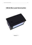
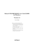
AB-320M
AB-330M
Mobile Printer
USER'S MANUAL
NOTICE
You must use only the supplied charger. It is
dangerous to use other chargers.
Do not plug or unplug with your hands
wet. You may be electrocuted.
Make sure the printer power is off before
plug or unplug the cable.
Keep magnetic objects away from
the printer.
Please don`t place the printer in
humidity or dusty space, excessive
humidity and dust may damage it.
Do not put foods or drinks on the
printer, in case that splash into
the printer.
The print head has a high temperature
after work. Please don`t touch the
print head or touch the motor shell
in case scalded.
Don't make battery short circuit or heated.
Otherwise the battery may be damaged or
cause fire or explode.
INTRODUCTION
AB-320M/AB-330M is the mobile printer model with excellent performance.
It is integrated with Serial, USB and Bluetooth interfaces. It can be easily
used for forms or receipts printing cooperated with portable equipments,
such as PDA, Laptop, Data Samplers etc.
The main features of the printer are as follows:
1. High speed printing: 60mm per second max.
2. Low noise thermal printing.
3. RS-232, USB, Bluetooth interfaces integrated.
4. The data buffer allows the unit to receive print data even during printing.
5. Bar code printing is possible by using a bar code command.
Please do read the instructions in this manual carefully before
using your new AB-320M/AB-330M
Table of Contents
Table of Contents........................................................................ 01
Chapter 1 Overview ................................................................... 02
Chapter 2 Setting up the Printer ............................................... 03
2-1. Unpacking ............................................................................ 03
2-2. Using the Printer ................................................................... 04
Chapter 3 Interfaces and cable connection.............................. 07
3-1. Interfaces .............................................................................. 07
3-2. Connect the cables................................................................ 09
Chapter 4 R oll paper installing .............................................. 10
4-1. Installing or Replacing the Roll Paper..................................... 10
4-2. Cleaning the Print Head......................................................... 11
Chapter 5 Battery installation.................................................... 12
Chapter 6 Self test ..................................................................... 13
Chapter 7 Basic operations ....................................................... 14
7-1. Power on/off........................................................................... 14
7-2. Feed paper............................................................................. 14
7-3. Tear paper.............................................................................. 14
Chapter 8 Alarming to lack of paper .......................................... 15
Chapter 9 Using and recharging battery.................................... 16
Chapter 10 Specifications .......................................................... 17
Chapter 11 Commands ............................................................... 18
WARNING
Some semiconductor devices are easily damaged by static
electricity. In order to guard the printer against the static electricity ,
you should turn the printer "OFF", before you connect or remove the
cables on the face side. If the printer is damaged by the static
electricity, you should turn the printer "OFF".
All specifications are subjected to change without notice.
11-1. Command List....................................................................... 18
11-2. Control Commands................................................................ 19
USER'S MANUAL
Chapter 1 Overview
Chapter 2 Setting up the Printer
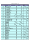
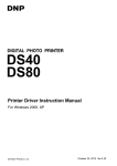
2-1. Unpacking
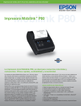
Below pictures define every part of printer model AB-320M/AB-320M.
Your printer box should include these items. If any of the items was damaged
or missing, please contact your dealer for assistance.
Ch
arge
Full
P ow
er
M
e
FEED
od
Erro
POWER
r
Roll paper
Shell
Operator s M anual
CH
ARGE FULL
PO
W
ER
OD
FE
M
Full(Green light)
Charge(Red light)
Feed Button
ED
E
PO
WE
R
ER RO
Power Button
Power(Red light)
Mode(Blue light)
R
Error(Yellow light)
USB Interface
AB-320M/AB-330M
Recharger
US
B
Printer Bag
Card Reader(MSR)
(Option)
Screw Hole
Strap Clasp
Screw Hole
Serial Interface
Recharge Port
Battery
USB Cable
Serial Cable
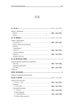
Below strap clasp is not included in the box but optional.The strap clasp is
fixed on the back shell of the printer using a nut inside and right behind the
back shell.
Screw Nut
Strap Clasp
USER'S MANUAL
USER'S MANUAL
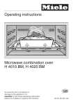
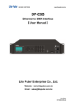
2-2. Using the Printer
BAUDRATE SETTING(For example:Set 9600BPS baudrate)
BUTTON
FEED
Press the FEED button once to advance paper one line. You can also hold
down the FEED button to feed paper continuously.
POWER
Press this button and hold on for a few second, the printer can be powered
on/off.
Before setting baudrate,make sure the printer is on off
1. Press POWER button and hold on till MODE light turns blue.
CH
ARGE FULL
PO
W
ER
OD
FE
M
ED
MODE
E
PO
WE
light turns blue
ER RO
R
R
PANEL LIGHTS
CHARGE
When the printer is connected with the charger, this light turns RED.
FULL
When the battery finished recharging, this light turns Green.
POWER
On-working indicator.
MODE
In mode-setting statue,it turns BLUE.
ERROR
Error appears,the light turns Yellow.
Status.
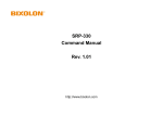
2. Press POWER button one time again.the
MODE
light will flash.
3. Press FEED button to Set baudrate.Press FEED button three times.
Press FEED one time is 2400BPS,Press two times is 4800BPS,Press
three times is 9600BPS.Once press FEED button one more time the
baudrate will be increased as below.
POWER
MOD
E
R
RO
ER
CH
AR
L
FUL
GE
FEED
POWER
CH
ARGE FULL
W
Press FEED button three times
to Set baudrate to 9600BPS
ER
M
OD
FE
PO
ED
E
WE
R
ERRO
PO
R
FE
ED
PO
USER'S MANUAL
USER'S MANUAL
WE
R
Press FEED button
One time
Two times
Three times
Four times
Five times
Six times
Seven times
Baudrate
2400BPS
4800BPS
9600BPS
19200BPS
38400BPS
57600BPS
115200BPS
Chapter 3 Interfaces and cable connection
3-1. Interfaces
This mobile printer model has three interfaces:
RS232, USB and Bluetooth. Below are the specifications.
3-1-1. RS-232C Cable Connection
PRINTER
SIDE
4.Press POWER button again to confirm baudrate Setting.The MODE
light will flash one or several times.Flash times is the Same as the times
you press the FEED button.
HOST
SIDE
(F.G) 1
1
(F.G)
(TXD) 3
(RXD) 2
3 (TXD)
2 (RXD)
7 (RTS)
8 (CTS)
(DSR) 6
(DTR) 4
6 (DSR)
4 (DTR)
(S.G) 5
5 (S.G)
Interface Connector
Serial Interface (RS-232)
CH
ARGE FULL
PO
W
ER
M
OD
FE
ED
MODE light will flash
E
WE
R
ERRO
PO
R
USER'S MANUAL
Pin No.
1
3
2
7
8
6
5
4
Signal name
FG
TxD
RxD
RTS
CTS
DSR
SG
DTR
Direction
Output
Input
Output
Input
Input
Output
USER'S MANUAL
Function
Frame Ground
Transmit Data
Receive Data
Ready To Send
Clear To Send
Date Set Ready
Signal Ground
Data Terminal Ready
3-1-2. USB Connection
3-2. Connect the cables
3-2-1. Connect the AC recharger to the printer to recharge the battery
Pin No
.
1
2
3
4
Signal name
VCC
DD+
GND
Direction
+ 5V DC
Data Data +
Ground
NOTE:To remove the DC cable connector, make sure that the power
supply`s power cord is unplugged; then grasp the connector and
pull it out straightly .
3-2-2. Connect the RS-232 port or USB port
Connect the Host Computer (POS/ECR) to the priter using an interface
cable that matches the specifications of the printer and the Host computer
(POS/ECR).
3-1-3. Bluetooth
As a global open standard, Bluetooth is an excellent wireless data
comunication technology. There is no need for bluetooth equipments to
transfer data of strict poistion and that differs from IrDA.It supports not
only point to point but also point to multipoints(Seven points for max).
This model is compatible with Bluetooth 2.0 standard and with power level
of Class 2. The original password of this model is 1234 . While printing,
the host and printer should be of distance less than 10 meters. If there is
any obstacle or EMI between host and printer, distance of less than 5 meters
is required.
1).
2).
3).
4).
Turn off both the printer and the Host computer (POS/ECR).
Plug the interface cable connector into the printer's interface connector.
Plug the other cable head into the Host computer(POS/ECR).
Turn on the Printer and Host computer(POS/ECR).
RS-232
USER'S MANUAL
USB
USER'S MANUAL
Chapter 4 Roll paper installing
4-2. Cleaning the Print Head
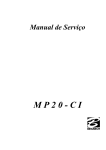
4-1. Installing or Replacing the Roll Paper
1. Make sure that the printer is not receiving data; otherwise, data may be
lost.
2. Grasp the two sides of the paper cabin cover and pull till the cover open.
3. Remove the used paper roll core if there is any.
4. Put in a new paper roll as shown.
5. Be sure the correct direction of the paper comes off the roll.
6. Pull out a small amount of paper, then close the cover. As picture shows.
A
B
Incorrect
C
Turn off the printer, open the paper roll cover, and clean the thermal elements
of the print head with a cotton swab moistened with an alcohol solvent
(ethanol, methanol, or IPA).
Recommend to clean the thermal head periodically (generally every three
months) to maintain receipt print quality.
D
USER'S MANUAL
Correct
NOTE: After printing, the print head can be very hot. Be careful not to
touch it and to let it cool before you clean it. Do not damage the print
head by touching it with your fingers or any other hard object.
USER'S MANUAL
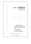
Chapter 5 Battery installation
The mobile printer is battery power supplied. Battery should be
fully recharged and properly installed in the printer before using.
Follow the picture steps as below:
1. invert the printer to the back battery cabin.
2. put the battery in the printer battery cabin in right position.
3. press the battery till a voice from the button.
A
Chapter 6 Self test
Self test checks whether the printer can perform normally or not, except to
functions of communication and recharging.
Follow the steps to initial a self test:
1. Make sure paper roll has been installed properly,
2. Press on the FEED button and hold on the POWER button for more than 3
seconds, then the self test performs.
3. The printer is ready to receive data after it fininshed the self test.
B
C
USER'S MANUAL
USER'S MANUAL
Chapter 7 Basic operations
Chapter 8 Alarming to lack of paper
7-1. Power on/off
Press on the POWER button and hold on for more than 3 seconds. The printer
will be powered on if the pre-statue is off; and the priner will be powered
off if the pre-statue is on.
Be sure the printer is powered on before printing. If the printer will not be
used for a long time, do please power it off to save battery power.
This printer can detect paper lacking.
When the printer run out of paper, the ERROR indicator light will turn yellow.
If the paper runs over when printing, the data in the printer buffer won't be
cleaned. The printing will go on after the paper loaded.
7-2. Feed paper
This printer can feed paper manually.
Press the FEED button once to advance paper one line. Press the FEED
button and hold on to feed paper continuously.
7-3. Tear paper
After finished printing every receipt, users need to tear off the receipt by
themselves. There is a sawtooth architecture for tearing. Pay special notice
to tearing angle and force , over force may results in roll paper being pulled
out from the paper cabin.
USER'S MANUAL
USER'S MANUAL
Chapter 9 Using and recharging battery
The mobile printer is power supplied by rechargeable Lithium-Ion battery.
As the battery can be easily damaged, the usage of battery affects the
battery's life span. Please use the battery properly under below instructions.
1. If the printer is not used for a long time (usually more than one week),
do please fetch out the battery for separate storage and better to fully
recharge the battery before fetching out the battery.
2. Power off the printer to save battery power after finished using.
3. When battery running over, the power indicator light would flash for
alarming. The printer can still work for an uncertain time, but users should
recharge the battery to ensure that the printer work properly.
Follow the below operations:
1. Plug the recharger into an outlet and plug the other terminal to the printer.
2. While recharging, the indicator light turns red. After recharge, the indicator
light turns green.
3. Please don't use the printer while recharging, otherwise the battery's life
span would be decreased.
USER'S MANUAL
Chapter 10 Specifications
AB-320M
AB-330M
Direct thermal line printing
Easy Paper Loading
Font A:48CPL,Font B:64CPL
Font A:12x24dots,Font B:9x24Dots
203dpi, 8dots/mm
48mm
72mm
60mm/sec
Manual Tearing
Thermal Paper
40mm
58mm
80mm
16k bits
Serial, USB, Bluetooth
1D:Codebar,ITF,UPC-A,UPC-E,CODE 39,CODE93,
CODE128,EAN-8,EAN-13
2D:QR CODE,PDF417
Battery Type Lithium-Ion
DC7.4V
Battery Output
Capacity
1100mAh
Input AC100~240V 50/60Hz 0.5A
Battery Charger
Output DC9V 1A
Operating Temperature 0 ~50
Storage Temperature 10 ~70
MCBF Electric Life
100,000,000 pulses
Wear Life
Paper feed length Approximately 50 Km
Battery
1200 Cycles Rechargeable
MSR
Auto 1/2/3 Track(Option)
Dimensions (WxDxH) 78x125 x 46 mm(No MSR)
100x121 x 46 mm(No MSR)
78 x132 x 46 mm(With MSR) 100 x128 x 46 mm(With MSR)
Weight
230g
280g
Printing
Paper Supply Method
Characters Per Line
Character Size
Resolution
Print Width
Printing Speed
Cutter Type
Paper Type
Paper Diameter
Paper Width
Receive Buffer Size
Interface
Barcodes
USER'S MANUAL
Chapter 11 Commands
11-1 Command List
No.
1
2
3
4
5
6
7
8
9
10
11
12
13
14
15
16
17
18
19
20
21
22
23
24
25
26
27
28
29
30
31
Command
HT
LF
FF
CR
CAN
DLE EOT
ESC FF
ESC SP
ESC !
ESC $
ESC *
ESC ESC 2
ESC 3
ESC @
ESC D
ESC E
ESC G
ESC J
ESC L
ESC M
EOT
ESC S
ESC T
ESC \
ESC a
ESC d
ESC A
ESC H
ESC I
ESC W
32
33
34
35
ESC X
ESC j
FS SO
FS DC 4
36
37
38
39
FS
GS
GS
GS
!
*
/
!
Description
Horizontal tab
Print and line feed
Page
Hexadecimal Code
20
< 09>
20
<0A>
20
<0C>
Print and carriage return
20
<0D>
20
Cancel print data in page mode
<18>
21
Transmission real-time status
<10><04><n>
22
Print data in page mode
<1B><0C>
22
Set right-side character spacing
<1B><20><n>
22
Select print mode(s)
<1B><21><n>
23
Set absolute print position
<1B><24><nL><nH>
23
Select bit image mode
<1B><2A><m><nL><nH>d1...dk
23
Turn under line mode on/off
<1B><2D><n>
24
Select default line spacing
<1B><32>
24
Set line spacing
<1B><33><n>
24
Initializing the printer
<1B><40>
24
Set horizontal tab positions
<1B><44>n1...nK<00>
25
Turn emphasized mode on / off
<1B><45><n>
25
Turn double-strike mode on/off
<1B><47><n>
25
Print and feed paper
<1B><4A><n>
25
Select page mode
<1B><4C>
25
Select character font./ MSR card read
<1B><4D><n>
26
Cancel card read mode
<04>
27
Select standard mode
<1B><53>
27
Select print direction in page mode
<1B><54><n>
27
Set relative print position
<1B><5C><nL><nH>
27
Select justification
<1B><61><n>
28
Print and feed n lines
<1B><64><n>
28
Set line spacing
<1B><41> <n>
28
Select character Double-height mode
<1B><48><n>
28
Select character Double-height mode
<1B><49>
29
Defining the print area in page mode
<1B><57>< xL>< xH>< yL>< yH>
< dxL>< dxH>< dyL>< dyH>
30
Select character Double-width mode
<1B><58><n>
30
Print and feed paper
<1B><6A><n>
30
Select character Double-width print mode <1C><0E>
30
Cancel character Double width print
<1C><14>
selection
31
Select character print mode
<1C><21><n>
31
Define downloaded bit image
<1D><2A><n1><n2>d1...dk
32
Print downloaded bit image
<1D><2F><m>
33
Select character size
<1D><21><n>
USER'S MANUAL
No . Command Description
40 GS $
Set absolute vertical print position
in page mode
41 GS (
Execute test print
42
GS (
43
GS (
44
45
GS (
GS (
46
GS (
47
GS B
48
49
50
51
52
GS
GS
GS
GS
GS
53
54
55
GS f
GS h
GS k
Turns white/black reverse
printing mode on or off
Transmits battery status
Transmits printer ID
Set left margin
Set printing area width
Set relative vertical print position
in page mode
Select font for HRI characters
Selects bar code height
Print bar code
56
57
GS r
GS W
Transmit status
Set bar code width
I
I
L
W
\
USER'S MANUAL
Hexadecimal Code
<1D><24><nL><nH>
Page
33
<1D><28><41><pL><pH>
<n><m>
<1D><28><45><pL><pH>
<fn><d1><d2>
<1D><28><45><pL><pH>
<fn><d1><d2><d3>
<1D><28><45><pL><pH><fn>..
<1D><28><45><pL><pH>
<0B><a><d1><dk>
<1D><28><45><pL><pH>
<fn><a>
<1D><42><n>
34
<1D><49><62>
<1D><49><n>
<1D><4C><nL><nH>
<1D><57><nL><nH>
<1D><5C><nL><nH>
38
39
40
40
40
<1D><66><n>
<1D><68><n>
(1)<1D><6B><m>d1...dk<NUL>
(2)<1D><6B><m><n>d1...dn
<1D><72><n>
<1D><77><n>
41
41
41
34
35
35
36
37
38
42
43
11-2 Control Commands
DLE EOT n
HT
[Name]
[Format]
[Name]
[Format]
[Description]
Horizontal tab
ASCII
HT
Hex
09
Decimal
9
Moves the print position to the next horizontal tab position.
[ Range ]
[Description]
n
1
4
LF
[Name]
[Format]
[Description]
Transmission real-time status.
ASCII
DLE EOT
n
Hex
10
04
n
Decimal
16
4
n
1
n
4
Transmits the status specified by n in real-time as follows:
Print and feed line
ASCII
LF
Hex
0A
Decimal
10
In standard mode, prints the data in the print buffer and feeds
one line based on the current line spacing.
In page move, modes the print position in memory to feed one
line based on the current line spacing.
This printer transmits the following status in real time.
n=1: Printer status
Bit
0
1
2
FF
3
[Name]
[Format]
[Description]
If in page mode, after printing, the printer is returned to regular mode.
If the label function is set, the paper is fed up to the next printing
position.
ASCII
FF
Hex
0C
Decimal
12
All data collected to the current point is printed, and then the printer
is converted from page mode to regular mode.
If the label function is set, the paper is fed up to the next printing
position.
4
5
6
7
[Description]
Bit
0
1
2
3
4
5,6
Print and carriage return
ASCII
CR
Hex
0D
Decimal
13
This command is ignored CR.
CAN
[Name]
[Format]
[Description]
7
[Notes]
Cancel print data in page mode.
ASCII
CAN
Hex
18
Decimal
24
In page mode, deletes all the print data in the current print area.
USER'S MANUAL
Off/On
Off
On
Off
Off
On
On
Off
Off
Off
Hex
00
02
00
00
08
10
00
00
00
Decimal
0
2
0
0
8
16
0
0
0
Function
Fixed
Fixed
Fixed
On-Line
Off-Line
Fixed
Fixed
Fixed
Fixed
n=4: Continuous paper sensor status
CR
[Name]
[Format]
Function
Transmit printer status.
Transmit paper roll sensor status.
Off/On
Off
On
Off
Off
On
On
Off
Off
Hex
00
02
00
00
10
20
00
00
Decimal
0
2
0
0
16
32
0
0
Function
Fixed
Fixed
Fixed
Fixed
Fixed
Paper end sensor: paper not present
Paper end sensor: paper present
Fixed
If print data includes a character string with this command,
the printer performs this command. User must consider this.
- Do not embed this command within another command.
- For example : Bit image data might include this command.
- This command is ignored block data is transmitted.
USER'S MANUAL
ESC FF
ESC $ nL nH
[Name]
[Format]
Print data in page mode.
ASCII
ESC FF
Hex
1B
0C
Decimal
27
12
In page mode, prints all buffered data in the printing area collectively.
[Description]
[Name]
[Format]
Set absolute print position.
ASCII
ESC $
nL nH
Hex
1B
24
nL
nH
Decimal
27
36
nL
nH
0 (nL + nH x 256) 65535 (0 nH 255, 0 nL 255)
Sets the next print starting position, and the absolute print
position, in reference to the left margin. The distance from
the beginning of the line to the left margin is
[(nL + nH x 256) x (vertical or horizontal motion units)].
[ Range ]
[Description]
ESC SP n
[Name]
[Format]
Set right-side character spacing.
ASCII
ESC SP
n
Hex
1B
20
n
Decimal
27
32
n
0
n
255
n=0
Sets the character spacing for the right side of the character to
[n x horizontal or vertical motion units].
The maximum right-side character spacing is : - 31.875mm.
[ Range ]
[Default]
[Description]
ESC * m nL nH d1...dk
[Name]
[Format]
Select bit image mode.
ASCII
ESC *
m
nL
nH d1...dk
Hex
1B
2A
m
nL
nH d1...dk
Decimal
27
42
m
nL
nH d1...dk
m=0, 1, 32, 33
1 (nL + nH x 256) 1023 (0 nL 255, 0 nH 3),0 d 255
Specifies the bit image in m mode for the number of dots specified
by nL and nH.
* dpi : dots per 25.4mm {1 }
[ Range ]
[Description]
ESC ! n
[Name]
[Format]
Vertical
Horizontal
Number Dot Density Dot Density Number of Data
of Dots
(dpi)
(dpi)
(K)
8-dot single-density
0
8
60
90
nL + nH x 2 56
1 8-dot double-density
8
60
180
nL + nH x 2 56
32 24-dot single-density
24
180
90
(nL + nH x 256) x 3
33 24-dot double-density
24
180
180
(nL + nH x 256) x 3
m
Select print mode(s).
ASCII
ESC !
n
Hex
1B
21
n
Decimal
27
33
n
0
n
255
n=0
Selects print mode(s) using n as follows.
[ Range ]
[Default]
[Description]
Mode
ESC - n
Bit
0
1,2
3
4
5
6
7
Off/On
Off
Off
Off
On
Off
On
Off
On
Off
Off
On
Hex
00
00
00
08
00
10
00
20
00
00
80
Decimal
0
0
0
8
0
16
0
32
0
0
128
Function
Character font A (12 x 24) selected
Reserved
Emphasized mode not selected
Emphasized mode selected
Double-height mode not selected
Double-height mode selected
Double-width mode not selected
Double-width mode selected
Reserved
Underline mode not selected
Underline mode selected
USER'S MANUAL
[Name]
[Format]
Turn underline mode on/off.
ASCII
ESC n
Hex
1B
2D
n
Decimal
27
45
n
0 n 2, 48 n 50
n=0
Turn underline mode on or off, based on the following values of n :
[ Range ]
[Description]
n
Function
0, 48
Turns off underline mode
1, 49
Turns on underline mode, set at 1-dot width
2, 50
Turns on underline mode, set at 2-dot width
USER'S MANUAL
ESC E n
ESC 2
[Name]
[Format]
[Description]
Select default line spacing.
ESC 2
ASCII
Hex
1B
32
Decimal
27
50
The default line spacing is about 4.23 mm {1/6 inch}, which is
equivalent to 30 dots.
[Name]
[Format]
[ Range ]
[Default]
[Description]
Turn emphasized mode on / off.
ASCII
ESC E
n
Hex
1B
45
n
Decimal
27
69
n
1
n
255
n=0
Turns emphasized mode on or off.
- When the LSB of n is 0, emphasized mode is turned off.
- When the LSB of n is 1, emphasized mode is turned on.
ESC 3 n
ESC G n
[Name]
[Format]
[ Range ]
[Description]
Set line spacing .
ASCII
ESC 3
n
Hex
1B
33
n
Decimal
27
51
n
0
n
255
The vertical or horizontal motion unit is approximately 0.125 mm
{1/203 inches}. This value equals one dot pitch.
Sets the current line spacing to [n x vertical motion units] inches.
The maximum settable line spacing is 31.875mm.
[ Range ]
[Description]
[ Range ]
[Default]
[Description]
Turn double-strike mode on/off.
ASCII
ESC G
n
Hex
1B
47
n
Decimal
27
71
n
1
n
255
n=0
Turns double-strike mode on or off.
- When the LSB of n is 0, double-strike mode is turned off.
- When the LSB of n is 1, double-strike mode is turned on.
ESC J n
ESC @
[Name]
[Format]
[Name]
[Format]
Initialize printer.
ASCII
ESC @
Hex
1B
40
Decimal
27
64
32
n
126
Clears the data in the print buffer and resets the printer mode to the
mode that was in effect when the power was turned on.
[Name]
[Format]
[ Range ]
[Description]
Print and feed paper.
ASCII
ESC J
n
Hex
1B
4A
n
Decimal
27
74
n
1
n
255
Prints the data in the print buffer and feeds the paper
[n X vertical motion unit].
ESC L
ESC D n1... nk NUL
[Name]
[Format]
[ Range ]
[Default]
[Description]
[Name]
[Format]
Set horizontal tab positions.
ASCII
ESC D
n1... nk NUL
Hex
1B
44
n1... nk 00
Decimal
27
68
n1... Nk 0
1
n
255,0
n
32
n=8, 16, 24, 32, 40,....., 232, 240, 248 (for font A in a standard
character size width)
Sets horizontal tab positions.
- n specifies the number of digits from the setting position to the left
margin or the beginning of the line.
- k specifies the number of bytes set for the horizontal tab position.
USER'S MANUAL
[Description]
Select page mode
ASCII
ESC L
Hex
1B
4C
Decimal
27
76
Switches from standard mode to page mode.
ESC M n
[Name]
[Format]
[ Range ]
[Default]
[Description]
Select character font/ MSR card read
ASCII
ESC M
n
Hex
1B
4D n
Decimal
27
77 n
n = 0, 1, 48, 49 , 67, 68, 69, 70, 71, 72, 73
n=0
Selects only-byte character fonts
Selects Card reader mode
USER'S MANUAL
n
ESC S
Function
0, 48
Character font A (12 x 24) selected.
70
Set 1 track card reader mode
71
Set 2 track card reader mode
[Description]
72
Set 1,2 track card reader mode
73
Transmits the setting value(s) of the memory switch 7
67
Set 2 track card reader mode
68
Set 3 track card reader mode
69
Set 2,3 track card reader mode
[Name]
[Format]
Select standard mode.
ASCII
ESC S
Hex
1B
53
Decimal
27
83
Switches from page mode to standard mode. Any data stored in
the printer for printing in page mode is cleared.
ESC T n
[Name]
[Format]
Magnetic card read out put format
[ Range ]
[Default]
[Description]
Track 1
02H 41H 31H 31H 1CH DATA 76 characters 03H 0DH 0AH
Track 2
Select print direction in page mode.
ASCII
ESC T
n
Hex
1B
54
n
Decimal
27
84
n
0 n 3, 48 n 51
n=0
Selects the print direction and starting position in page mode.
02H 42H 31H 31H 1CH DATA 37 characters 03H 0DH 0AH
n
Print Direction
Starting Position
Track 1,2
0,48
Left right
Upper left
02H 43H 31H 31H 1CH 1CH DATA 76 characters 1CH DATA 37characters 03H 0DH 0AH
Track 3
02H 44H 31H 31H 1CH DATA104characters 03H 0DH 0AH
Track 2,3
02H 45H 31H 31H 1CH 1CH DATA 37characters 1CH DATA104 characters 03H 0DH 0AH
Decimal
37H
55
1byte
Flag
80H
128
1byte
Data
30H ~ 37H
48 ~ 55
1byte
NUL
00H
0
1 byte
EOT
[Description]
[Name]
[Format]
Amount of Data
Header
[Name]
[Format]
nL nH
[ Range ]
[Description]
Transmits the setting value output format
Hexadecimal
ESC
ESC a n
[Name]
[Format]
Cancel card read mode
ASCII
EOT
Hex
04
Decimal
4
Cancel card read mode
Works the same as when the POWER button is pressed
USER'S MANUAL
Set relative print position.
ASCII
ESC \
nL nH
Hex
1B
5C nL nH
Decimal
27
92 nL nH
0 (nL + nH x 256) 65535 (0 nL 255, 0 nH 255)
Set the print starting position based on the current position to
[(nL + nH X 256) X horizontal or vertical motion unit]
- When (nL + nH X 256) is positive number, the print starting
position is specified to the right based on the current position.
- When (nL + nH X 256) is negative number, the print starting
position is specified to the left based on the current position.
[ Range ]
[Default]
[Description]
Select justification.
ASCII
ESC a
n
Hex
1B
61
n
Decimal
27
97
n
0 n 2, 48 n 50
n=0
In standard mode, aligns all the data in one line to the position
specified by n as follows :
USER'S MANUAL
n
Justification
0, 48
Left justification
1, 49
Centering
2, 50
Right justification
[ Range ]
[Description]
Print and feed n lines.
ASCII
ESC d
n
Hex
1B
64
n
Decimal
27
100 n
0 n 255
Prints the data in the print buffer and feeds n lines.
ESC A n
[Name]
[Format]
[Range]
[Description]
[Details]
[Default]
Set line spacing
ASCII
ESC
A
n
Hex
1B
41 n
Decimal
27
65 n
0
n
255
Sets the line spacing to [n x vertical or horizontal motion unit].
The line spacing can be set independently in standard mode and in
page mode.
The maximum paper feed amount is 1016 mm {40"}. Even if a
paper feed amount of more than 1016 mm {40"}is set, the printer
feeds the paper only 1016 mm {40"}.
Approx 4.23mm {1/6"}.
ESC H n
[Name]
[Format]
[Range]
[Description]
[Name]
[Format]
[Range]
[Description]
ESC d n
[Name]
[Format]
ESC W xL xH yL yH dxL dxH dyL dyH
Select character Double-height mode
ASCII
ESC
H
n
Hex
1B
48
n
Decimal
27
72
n
1
n
8
Select character Double-height mode.
[Details]
Defining the print area in page mode
ASC II
ESC
W
xL xH yL yH dxL dxH dyL dyH
Hex
1B
57 xL xH yL yH dxL dxH dyL dyH
Decimal
27
87
xL xH yL yH dxL dxH dyL dyH
0 xL, xH, yL, yH, dxL, dxH, dyL, dyH 255
Defines the location and size of the print area.
Horizontal start point = [(xL + xH x 256) x basic calculation pitch]
inches
Vertical start point = [(yL + yH x 256) x basic calculation pitch]
inches
Horizontal length = [(dxL + dxH x 256) x basic calculation pitch]
inches
Vertical length = [(dyL + dyH x 256) x basic calculation pitch]
inches
When standard mode is selected, this command only executes the
internal flagging of the printer without affecting the printing in
standard mode.
If the horizontal start point or vertical start point is out of the
printable area, this command is canceled and the next data is
handled as normal data.
If the horizontal length or vertical length is 0, this command is
canceled and the next data is handled as normal data.
If the horizontal start point + horizontal length is greater than
the horizontal printable area, the horizontal printable area horizontal start point is taken as the horizontal length.
If the vertical start point + vertical length is greater than the
vertical printable area, the vertical printable area vertical start
point is taken as the vertical length.
Fractions resulting from calculations are corrected with the
minimum pitch of the mechanism, and the remainder are omitted.
The horizontal start point and horizontal length are calculated with
the basic calculation pitch (x). The vertical start point and vertical
length are calculated with the basic calculation pitch (y).
When the horizontal starting position , vertical starting position,
printing area width, and printing area height are defined as X, Y,
Dx,and Dy respectively, the printing area is set as shown in the
figure below.
(X,Y)
Dx
ESC I
[Name]
[Format]
[Description]
Select character Double-height mode
ASCII
ESC
I
Hex
1B
49
Decimal
27
73
Select character Double-height mode.
USER'S MANUAL
Dy
Print area
(X+Dx-1,Y+Dy-1)
USER'S MANUAL
Paper Feed Direction
[Default]
This printable area for this printer is approximately 72.2 mm
{512/180"}in the horizontal direction and approximately 117.3 mm
{1662/360"} in the vertical direction.
XL = xH = y L = yH = 0
dxL = 0, dxH = 2, dyL = 126, dyH = 6
FS ! n
[Name]
[Format]
Select character print mode
ASCII
FS
!
n
Hex
1C
21
n
Decimal
28
33
n
[Range]
[Description]
0<n <255
Select print modes using n as follows
ESC X n
[Name]
[Format]
[Range]
[Description]
Select character Double-width mode
ASCII
ESC
X
n
Hex
1B
58 n
Decimal
27
88 n
1
n
8
Select character Double-width mode.
Bit
0
1
2
3
4
5
6
7
ESC j n
[Name]
[Format]
[Range]
[Description]
[Details]
Print and feed paper
ASCII
ESC
j
n
Hex
1B
6A
n
Decimal
27
106
n
0
n
255
Prints the data in the print buffer and feed the paper [n x vertical or
horizontal motion unit].
After printing is completed, this command sets the print starting
position to the beginning of the line.
The paper feed amount set by this command does not affect the
values set by ESC 2 or ESC 3.
In standard mode, the printer uses the vertical motion unit (y).
The maximum line spacing is 1016mm {40"}. When the setting
value exceeds the maximum, it is converted to the maximum
automatically.
FS SO
[Default]
GS
[Name]
[Format]
[Description]
Select character Double-width print mode
This order can be canceled by FS,DC4,LF order.
[Details]
[Description]
USER'S MANUAL
On
On
----
4
8
-
4
8
-
Function
Default font
Undefined
Double-height mode selected
Double-width mode not selected
Undefined
Undefined
Undefined
Undefined
n1 n2 d1...d(n1 x n2 x 8)
[Range]
[Description]
Cancel character Double width print selection
ASCII
FS
DC4
Hex
1C
14
Decimal
28
20
This order can cancel character Double-width print mode set by
FS, SO.
Decimal
n=0.
Select character Double-width print mode
ASCII
FS
SO
Hex
1C
0E
Decimal
28
14
[Name]
[Format]
Hex
If n is in the range of defination ,this order can be neglected.When
both double -height and double-width modes are selected, characters
are printed simultaneously
[Name]
[Format]
FS DC 4
Off/On
Define downloaded bit image
ASCII
GS
*
n1
n2
d1...d(n1 x n2 x 8)
Hex
1D
2A n1
n2
d1...d(n1 x n2 x 8)
Decimal
29
42 n1
n2
d1...d(n1 x n2 x 8)
1
n1
255, 1 n2 48, n1 x n2
1536 , 0 d
255
Defines a downloaded bit image using the number of dots
specified by n1 and n2
-n1 specifies the number of dots in the horizontal direction.
-N2 specifies the number of dots in the vertical direction.
The number of dots in the horizontal direction is n1 x 8, in the
vertical direction it is n2 x 8.
If n1 x n2 is out of the specified range, this command is disabled.
The d indicates bit-image data. Data (d) specifies a bit printed to 1
and not printed to 0.
The downloaded bit image definition is cleared when:
1. ESC @ is executed.
2. Printer is reset or the power is turned off.
The following figure shows the relationship between the
downloaded bit image and the printed data.
USER'S MANUAL
GS ! n
n1 x 8 dost
d1
dn2 + 2
dn2 + 2 + 1
dn2 + 2
dn2 + 2 + 1
MSB
[Name]
[Format]
Select character size.
ASCII
GS
!
n
Hex
1D
21 n
Decimal
29
33 n
1
n
255
(where 1 Enlargement in vertical direction 8, 1 Enlargement
in horizontal direction 8)
n=0
Selects character size (enlargement in vertical and horizontal
directions).
d2
[ Range ]
n2 x 8 dost
LSB
[Default]
[Description]
dn2
d 2 x n2 x 8
dn2 x 2
[See Also]
GS /
GS / m
[Name]
[Format]
[Range]
[Description]
Print downloaded bit image
ASCII
GS
/
m
Hex
1D
2F
m
Decimal 29
47
m
0
m
3, 48
m
51
Prints a downloaded bit image using the mode specified by m.
Modes that can be selected by m are shown below.
m
0,48
1,49
2,50
3,51
[Details]
[See Also]
Dot Density in
Dot Density in
Vertical Direction Horizontal Direction
NORMAL MODE
203 DPI
203 DPI
DOUBLE WIDTH MODE
203 DPI
101 DPI
DOUBLE HEIGHT MODE
101 DPI
203 DPI
QUADRUPLE SIZE MODE
101 DPI
101 DPI
Mode Name
When data exists in the print buffer, this command is ignored.
When a downloaded bit image has not been defined, this
command is ignored.
A portion of a downloaded bit image exceeding one line length is
not printed.
A downloaded character and a downloaded bit image cannot be
defined simultaneously.
GS *
USER'S MANUAL
Bit
0
1
2
3
4
5
6
7
Function
Setting
Specifies the number of times enlarged
in the vertical direction
Refer to Table 2
[Enlarged in vertical direction]
Specifies the number of times enlarged
in the horizontal direction
Refer to Table 1
[Enlarged in horizontal direction]
Table 1 Enlarged in horizontal direction
Hex
00
10
20
30
40
50
60
70
Decimal
0
16
32
48
64
80
96
112
1
2
3
4
5
6
7
8
Enlargement
time(Standard)
times
times
times
times
times
times
times
Table 2 Enlarged in vertical direction
Hex
00
01
02
03
04
05
06
07
Decimal
0
1
2
3
4
5
6
7
1
2
3
4
5
6
7
8
Enlargement
time(Standard)
times
times
times
times
times
times
times
GS $ nL n H
[Name]
[Format]
[ Range ]
[Description]
Set absolute vertical print position in page mode.
ASCII
GS
$
nL nH
Hex
1D
24 nL nH
Decimal
29
36 nL nH
0 (nL + nH x 256) 65535 (0 nL 255, 0 nH 255)
Sets the absolute vertical print starting position to
[(nL + nH X 256)X (vertical or horizontal motion units)].
USER'S MANUAL
GS ( A pL pH n m
[Name]
[Format]
[ Range ]
[Description]
Execute test print.
ASCII
GS ( A pL p H n m
Hex
1 D 28 41 p L pH n m
Decimal 29 40 65 pL pH n m
(pL + pH x 256) = 2 (pL=2, pH=0)
0 n 2, 48 n 50
1 m 3, 49 m 51
Executes a test print with a specified test pattern on a specified
paper type (roll paper).
n specifies the paper type as listed below to be tested :
n
Header
m
32
1byte
1 byte
The following commands are enabled in the user setting mode.
<Function 2> through <Function 12> of GS ( E, GS I.
<Function 2> GS ( E pL pH fn d1 d2 d3 (fn=2)
[Format]
[Description]
Test pattern
2, 50
Self Test Printing
3, 51
Self Test rolling pattern
<Function 1> GS ( E pL pH fn d1 d2 (fn=1)
[ Range ]
[Description]
ASCII
GS ( E pL p H fn d1 d 2 d3
Hex
1D 28 45 pL pH fn d1 d2 d3
Decimal 29 40 69 pL pH fn d1 d2 d3
(pL + pH x 256) = 4 (pL=4, pH=0)
fn=2
d1=79, d2=85,d3=84
Ends the user setting mode and performs a software reset.
Therefore, the printer clears the data received in print buffers,
and resets all settings (user-defined character, downloaded
bit images, macros, and the print mode) to the mode that was
in effect at powering on.
This function code (fn=2) is enabled only in the user setting mode.
Hexadecimal dump
If this command is processed while a macro is being defined, the printer
cancels macro definition and starts processing this command. At that
time, the macro becomes undefined.
After processing this command, the printer performs a software reset.
[Format]
1byte
0
<Function 3> GS ( E pL pH fn [a1 b18...b11]...[ak bk8...bk1] (fn=3)
[Format]
[Notes]
55
20H
m specifies a test pattern as listed below :
1, 49
37H
00H
Paper roll
2, 50
Number of Data
NUL
[ Range ]
1, 49
Decimal
Flag
Paper type
0, 48
Hexadecimal
ASCII
GS ( E pL p H fn d1 d 2
Hex
1D 28 45 pL pH fn d1 d2
Decimal 29 40 69 pL pH fn d1 d2
(pL + pH x 256) = 3 (pL=3, pH=0)
fn=1
d1=73, d2=78
Enter the user setting mode and notifies that the mode has changed.
USER'S MANUAL
[ Range ]
[Default]
[Description]
ASCII
GS (
E pL pH fn [a1 b18...b11]... [ak bk8...bk1]
Hex
1D 28 45 pL pH fn [a1 b18...b11]... [ak bk8...bk1]
Decimal 29 40 69 pL pH fn [a1 b18...b11]... [ak bk8...bk1]
10
(pL + pH x 256) 65535
fn=3
a= 5
b=48, 49,50
All switches are set to Off (b=48).
Change the memory switch specified by a to the values
specified by b.
- When b=48, the applicable bit is turned to Off.
- When b=49, the applicable bit is turned to On.
- When b=50, the applicable bit is not changed.
When a=5 the memory switch 5 is set as follows :
Set power off time (1~90 minute.) *When memory switch setting
value 0, not work power off
USER'S MANUAL
MSW5-8 MSW5-7 MSW5-6 MSW5-5 MSW5-4 MSW5-3 MSW5-2 MSW5-1 Value
48
48
48
48
48
48
48
48
0
48
48
48
48
48
48
48
49
1
48
48
48
48
48
48
49
48
2
48
48
48
48
48
48
49
49
3
48
48
48
48
48
49
48
48
4
48
49
48
49
49
48
49
48
90
<Function 12> GS ( E pL pH fn a (fn=12)
[Format]
[ Range ]
[Description]
<Function 11> GS ( E pL pH fn a d1...dk (fn=11)
[Format]
ASCII
GS (
E pL p H fn a d1 d k
Hex
1D 28 45 pL pH 0B a d1 dk
Decimal
29 40 69 pL pH 11 a d1 dk
3 (pL + pH x 256) 8 (3 pL 8,0 pH 255)
fn=11, 1 a
4
48 d 57 [a=1]
48 d 50 [a=2]
d=48,49 [a=3]
d=55,56 [a=4]
1 k 6
d1..dk= 19200 [a=1]
d=48[a=2]
d=48[a=3]
d=56[a=4]
sets the configuration item for the serial interface specified by a
to the values specified by d1..dk
[ Range ]
[Default]
[Description]
Flow control
4
Data length
Amount of Data
1 byte
Flag
33H
39
1 byte
31H - 34H
49-52
1 byte
1 byte
Type of the
Communication condition
Setting value
NUL
Data length
Parity
3
55
Separator
4
2
Decimal
Configuration item
Parity
Baud rate
37H
Transmission speed
Flow control
Communication Condition
1
Hexadecimal
a
2
a
Header
1
3
ASCII
GS
( E pL pH f n a
Hex
1D 28 45 pL pH fn a
Decimal 29 40 69 pL pH fn a
(pL + pH x 256) = 2 (pL=2, pH=0)
fn=12, 1 a 4
Transmits the communication conditions of the serial
interface specified by a.
1FH
31
30H - 39H
48 - 57
00H
0
1 - 6 bytes
1 byte
Configuration of the setting value
- When the baud rate (a=1) is specified :
Transmission speed (a=1) is specified by number:
Example : When defining 19200 bps : 5bytes d1...dk 19200
(Hexadecimal = 31H,39H,32H,30H,30H /Decimal= 49,57,50,48,48)
Parity (a=2) is specified by d as follows :
d
48
Function
Select no parity
Flow control(a=3) is specified by d as follows:
d
48
Function
Select Flow control DTR/DSR
Data Length(a=4) is specified by d as follows:
d
Function
56
Select 8bit length
USER'S MANUAL
Baud rate (bps)
d1
d2
d3
d4
d5
d6
2400
50
52
48
48
--
--
4800
52
56
48
48
--
--
9600
57
54
48
48
--
--
19200
49
57
50
48
48
--
38400
51
56
52
48
48
--
57600
53
55
54
48
48
--
115200
49
49
53
50
48
48
USER'S MANUAL
When the parity setting (a=2) is specified :
d1
Parity
48
No parity (Fixed)
-When the flow control setting (a=3) is specified :
d1
Flow control
48
DTR / DSR (Fixed)
Transmitted data
Hex
Decimal
Amount of data
Header
37H
55
1byte
Identifier
Battery remaining
NUL
Battery remaining amount
45H
69
1byte
30h-34H
48-52
1byte
00H
0
1byte
is as indicated in the following table.
Battery remaining amount:
-When the data length setting (a=4) is specified :
Hex
Decimal
d1
Data length
30H
48
Battery remaining amount : H level
56
8 bits (Fixed)
31H
49
Battery remaining amount : M level
If a is out of range, this command ignores the value which is
specified with a.
Information
32H
50
Battery remaining amount :L level
33H
51
Battery remaining amount :S level
34H
52
Battery isn't installed
GS B n
[Name]
[Format]
[ Range ]
[Default]
[Description]
Turns white/black reverse printing mode on / off.
ASCII
GS
B
n
Hex
1D
42
n
Decimal
29
66
n
0 n
255
n=0
Turns white/black reverse printing mode on or off.
- When the LSB of n is 0, white/black reverse mode is turned off.
- When the LSB of n is 1, white/black reverse mode is turned on.
GS I b
[Name]
[Format]
[Description]
[Notes]
Transmits battery status.
ASCII
GS
I
b
Hex
1D
49
62
Decimal
29
73
98
Transmits the battery power status of the printer
The transmitted battery status from this printer is constructed by
[Header ~ NUL] as shown in the
USER'S MANUAL
GS I n
[Name]
[Format]
[ Range ]
[Description]
Transmits printer ID.
ASCII
GS
I
n
Hex
1D
49
n
Decimal
29
73
n
65
n
69
Transmits the printer ID specified.
- n specifies the printer information.
n
Printer ID type
65
Firmware version
Depends on firmware version
ID
66
Manufacturer
ZONERICH
67
Printer name
AB-320M/AB-330M
69
Font of Language for each country
Chinese : CHINA GB2312
USER'S MANUAL
GS L nL
GS f n
nH
[Name]
[Format]
Set left margin.
ASCII
GS L
nL nH
Hex
1D 4C
nL nH
Decimal
29 76
nL nH
1
nL
255,0
nH
255
(nL + nH x 256)=0 (nL=0, nH=0)
[ Range ]
[Default]
[Description]
[Name]
[Format]
[ Range ]
[Default]
[Description]
Sets the left margin specified by nL and nH.
- The left margin is [(nL + nH x 256) x (horizontal motion units)].
Select font for HRI characters.
ASCII
GS
f
n
Hex
1D
66
n
Decimal
29
102
n
For ANK/Multilingual model : n=0, 1, 48, 49
n=0
Selects a font for the HRI characters used when printing a bar code.
- n specifies the font of the HRI characters as follows :
Printable area
Left margin
GS W nL
Printing area width
[Name]
[Format]
[ Range ]
[Default]
[Description]
Set printing area width.
ASCII
GS W
nL nH
Hex
1D 57
nL nH
Decimal
29 87
nL nH
0 nL
255,0
nH
255
(nL + nH x 256)=384 (nL=128, nH=1) (for 58mm of the paper width)
Sets the printing area width specified with nL and nH.
- The printing area width is
[(nL + nH x 256) x (horizontal motion units)].
Printable area
Left margin
[ Range ]
[Default]
[Description]
[Name]
[Format]
Printing area width
nH
[Description]
[Name]
[Format]
[ Range ]
[Description]
Set relative vertical print position in page mode.
ASCII
GS \
nL nH
Hex
1D 5C
nL nH
Decimal
29 92
nL nH
0 nL
255,0
nH
255
Sets the relative vertical print starting position from the current
position in page mode. The distance from the current position to
the starting position is
[(nL + nH x 256) x (vertical or horizontal motion units)].
USER'S MANUAL
0, 48
Font A (12 x 24)
Selects bar code height.
ASCII
GS
h
n
Hex
1D
68
n
Decimal
29
104
n
1
nL
255
n=162
Selects the height of the bar code as n dots.
(1) GS k m d1...dk NUL
(2) GS k m n d1...dn
[Range]
GS \ nL
Font
GS h n
[Name]
[Format]
nH
n
Print bar code
(1) ASCII
GS
k
m
d1...dk
NUL
Hex
1D
6B m
d1...dk
NUL
Decimal
29
107 m
d1...dk
NUL
(2) ASCII
GS
k
m
n
d1...dn
Hex
1D
6B m
n
d1...dn
Decimal
29
107 m
n
d1...dn
(1) 0 m
6 (k and d depend on the bar code system used)
(2) 65 m
73 (n and d depend on the bar code system used)
Selects a bar code system and prints the bar code.
For (1) :
m
2
3
Bar Code System
JAN13 (EAN)
JAN 8 (EAN)
4
CODE39
Range of K
12
k
13
7
k
8
1
USER'S MANUAL
k
Range of d
48
d
57
48
d
57
48
d
57, 65 d
90,
d=32, 36, 37, 43, 45, 46, 47
GS W n
For (2) :
m
67
68
[Notes]
Bar Code System
JAN13 (EAN13)
JAN 8 (EAN8)
Range of k
12
k
13
7
k
8
69
CODE39
1
k 255
73
CODE128
2
k 255
Range of d
48
d
57
48
d
57
48
d
57, 65 d
90,
d=32, 36, 37, 43, 45, 46, 47
0
d
127
User most consider the quiet zone of the bar code (left and right
spaces of the bar code)
[Name]
[Format]
[ Range ]
[Description]
n
Set bar code width.
ASCII
GS
w
n
Hex
1D
77
n
Decimal
29
119
n
2 n 6,n=3
Set the horizontal size of the bar code, using n as follows :
Multi-level Bar Code
Module Width (mm)
GS r n
[Name]
[Format]
[ Range ]
[Description]
Transmit status.
ASCII
GS
r
n
Hex
1D
72
n
Decimal
29
114
n
n=1,2,49,50
Transmits the normal status specified by n as follows :
n
Function
1, 49
Transmits paper sensor status.
Binary-level Bar Code
Thin element width(mm) Thick element width (mm)
2
0.282
0.282
0.706
3
0.423
0.423
1.129
4
0.564
0.564
1.411
5
0.706
0.706
1.834
6
0.847
0.847
2.258
[Notes]
Multi-level bar codes are as follows :
- UPC-A, UPC-E, JAN13, HAN8, CODE93, CODE128
Binary-level bar codes are as follows :
-CODE39, ITF, CODABAR
Paper sensor status (n=1, 49) :
Bit
0,1
2,3
4
5
6
7
Off/On
Off
Off
On
Off
Off
Off
Off
Hex
00
00
0C
00
00
00
00
Decimal
0
0
12
0
0
0
0
Function
Paper roll near-end sensor : paper adequate.(Fixed)
Paper roll end sensor : paper present
Paper roll end sensor : paper not present
Fixed
Reserved
Reserved
Fixed
- Bits 2 and 3 : This command cannot be executed since the printer becomes
offline when the paper roll end sensor detects the paper not present. Therefore, the
status of bit 2 (1) and bit 3 (1) is not transmitted.
USER'S MANUAL
USER'S MANUAL