1
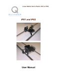
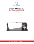
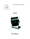
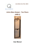
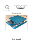
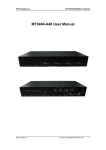
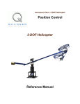
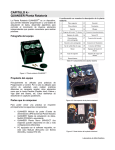
Quanser Accessories: UPM-15-03, UPM-24-05, and UPM-180-25B Universal Power Module (UPM) User Manual UPM User Manual Table of Contents 1. Introduction..........................................................................................................................1 2. Linear Amplifier Modules: UPM-15-03 and UPM-24-05...................................................2 2.1. Specifications...............................................................................................................2 2.2. System Description......................................................................................................3 2.3. Wiring..........................................................................................................................6 2.3.1. Cable Nomenclature.............................................................................................6 2.3.2. Common Connections..........................................................................................9 2.3.3. Circuit Schematic.................................................................................................9 3. PWM Module: UPM-180-25B..........................................................................................10 3.1. Specifications.............................................................................................................10 3.2. Description.................................................................................................................11 3.3. Safety Features...........................................................................................................14 3.3.1. Limit Switches....................................................................................................14 3.3.2. Emergency Stop Switch.....................................................................................15 3.4. Typical Connections..................................................................................................15 3.4.1. Cable Nomenclature...........................................................................................16 3.4.2. Wiring Procedure...............................................................................................17 3.5. Using the UPM-180-25B...........................................................................................17 3.5.1. Initialization.......................................................................................................17 3.5.1.1. Initialization Procedure using WinCon......................................................18 3.5.1.2. Initialization Signals...................................................................................19 3.5.1.3. Simulink Model: q_boot_upm_zz.mdl.......................................................20 3.5.2. Enabling.............................................................................................................20 3.5.2.1. Enabling Signals.........................................................................................20 3.5.2.2. Simulink Model..........................................................................................21 3.5.3. Calibration..........................................................................................................22 3.5.3.1. Calibration Signals.....................................................................................22 3.5.3.2. Simulink Model..........................................................................................23 3.6. Troubleshooting Guide..............................................................................................24 4. Obtaining Support..............................................................................................................25 5. References..........................................................................................................................25 Document Number: 528 Revision: 02 Page: i UPM User Manual 1. Introduction The Quanser Universal Power Module (UPM) is a power amplifier that is designed to drive the actuators of various Quanser experiments. Every UPM consists of the following components: Power amplified analog output Regulated ±12 V DC power supply at 1-Ampere Analog sensor inputs Table 1 summarizes the different UPM models available and some general specifications. Model Max Output Voltage (V) Max Continuous Current (A) Type Mode UPM-15-03 ±15.0 3.0 Linear Voltage UPM-24-05 ±24.0 5.0 Linear Voltage UPM-180-25B ±169.7 25.0 PWM Current Table 1 UPM models. The UPM-15-03 and the UPM-24-05 are both linear voltage-controlled amplifiers. The UPM-15-03 device, pictured in Figure 1, is capable of delivering a maximum continuous voltage of ±15 V and a maximum continuous current of 3 A. For actuators requiring more power, the UPM-24-05 has a maximum continuous voltage of ±24 V and a maximum continuous current of 5 A. In more high-powered applications such as the Quanser Shake Table II or the Quanser High-Fidelity Linear Cart, the UPM-180-25B shown in Figure 2 is used. The UPM's onboard current-controlled pulse-width modulated amplifier outputs pulse amplitudes of 169.7 V and it can deliver a maximum continuous current of 25 A. Document Number: 528 Revision: 02 Page: 1 UPM User Manual Figure 1 Quanser UPM-15-03 Figure 2 Quanser UPM-180-25B 2. Linear Amplifier Modules: UPM-15-03 and UPM-24-05 In this section, the linear voltage-controlled amplifiers UPM-15-03, shown in Figure 1, and UPM-24-05 are described. As mentioned, the output of these module are made to be connected with the actuator of various Quanser experiments. Typically the output of the UPM is connected to a DC motor (with or without an internal gearbox) such as in the SRV02 or IP02 experiments. It can also be used to drive an electromagnet as in the Quanser Maglev plant or a pump like in the Quanser Coupled-Tanks experiment. 2.1. Specifications The UPM-15-03 device has a linear power amplifier that is capable of supplying a continuous voltage of ±15 V and continuous currents of up to 3 A. The amplifier is in voltage-mode thus an input voltage of 1 V results in a regulated voltage of Kv in the connected motor. See Table 2 for the main specifications associated with the UPM-15-03. Document Number: 528 Revision: 02 Page: 2 UPM User Manual Symbol Kv Parameter Amplifier Voltage Gain Vmax Amplifier Maximum Continuous Voltage Ia_max Amplifier Maximum Continuous Line DC Current Vdc DC Output Voltage Supply Idc_max Vin DC Output Maximum Current Supply Supply AC Voltage Value Units 1,3, or 5 V/V ±15 V 3 A ±12 V 1 A 100/120/ 230/240 V Table 2 Specifications of the UPM-15-03 device. The UPM-24-05 is a more powerful version of the UPM-15-03 that is capable of supplying a continuous voltage of ±24V and a maximum continuous current of 5 A. Its specifications are given in Table 3. Symbol Kv Parameter Amplifier Voltage Gain Vmax Amplifier Maximum Continuous Voltage Ia_max Amplifier Maximum Continuous Line DC Current Vdc DC Output Voltage Supply Idc_max Vin DC Output Maximum Current Supply AC Supply Voltage Value Units 1,3, or 5 V/V ±24 V 5 A ±12 V 1 A 100/120/ 230/240 V Table 3 Specifications of the UPM-24-05 device. 2.2. System Description The components on the front panel of the UPM-15-03 and the UPM-24-05 is depicted in Figure 3. Each component on the UPM has an identification number that corresponds to a the short description given in Table 4. Document Number: 528 Revision: 02 Page: 3 UPM User Manual Figure 3 Front panel of UPM-15-03 / UPM-24-05. ID # Description ID # Description 1 Breadboard 11 Analog sensor input 3 connector. 2 UPM Power LED. 12 Analog sensor input 4 connector. 3 -12 V terminal of DC power supply. 13 Analog signals available to DAC device. 4 Ground terminal of DC power supply. 14 Input control signal from DAC. 5 12 V terminal of DC power supply. 15 Negative power amplifier input terminal. 6 Analog sensor input 1 terminal. 16 Positive power amplifier input terminal. 7 Analog sensor input 2 terminal. 17 Amplifier output terminal. 8 Analog sensor input 3 terminal. 18 Amplifier ground. 9 Analog sensor input 4 terminal. 19 Amplifier actuator. output connector to 10 Analog sensor input 1 and 2 connector. Table 4 Front panel components on UPM-15-03 / UPM-24-05. Document Number: 528 Revision: 02 Page: 4 UPM User Manual As depicted in Figure 3, a breadboard (component #1) is mounted on top of each UPM. This can be used to construct analog circuits such as a low-pass filter using operational amplifiers. As previously mentioned, the UPM also contains an independent ±12 power supply with three -12 V (ID #3), Ground (ID #4), and +12 V (ID #5) terminals. This can of course be used with the breadboard circuit to power an integrated circuit. The "From Analog Sensors" connectors are used to connect analog sensors such as potentiometers, pressure sensors, and accelerometers. The UPM-15-03 and UPM-24-05 devices have three 6-pin mini DIN connectors labeled "S1 & S2", "S3", and "S4" with ID #10, 11, and 12, respectively. These connectors provide a ±12 VDC bias to analog sensors and carry their voltage signals back to the UPM. The sensor signals can be measured from the four "Test Points" connectors, labeled #6-9 in Figure 3, or the "To A/D" connector, ID #13 in Figure 3. The "Test Points" connectors are useful when it is desired to interface the sensor signals with an analog circuit or monitor the signals externally using an oscilloscope. On the other hand, the "To A/D" connector is handy to connect the analog sensor signals to a data-acquisition terminal board. The control signal that is outputted from the digital-to-analog output channel on the DAC board is usually connected to the UPM "From D/A" connector (ID #14). Alternatively, it may be easier to connect a control signal coming from an analog circuit to the "-", ID #15, and/or "+", ID #16, connectors underneath the "Power Amplifier #1" label in the front panel of the UPM. The resulting amplified signal is available at the "OUT" (ID #17) terminal and the "To Load" connector (ID #19). The "OUT" terminal may be used to feed the amplified signal to an analog circuit or to monitor external using a voltmeter. The "To Load" 6-pinDIN connector is typically used to interface the amplified with the a Quanser plant. The gain of the UPM-15-03 and the UPM-24-05 power amplifier, either 1, 3, or 5, is set by using the appropriate "To Load" gain cable of 1, 3, or 5. The cable contains the feedback resistor of the amplifier that effectively sets its amplification factor. See Table 5 in Section 2.3.1 for a description of the gain cables. CAUTION: Always ensure you are using the correct "To Load" gain cable! The linear amplifier voltage gain in both the UPM-15-03 or the UPM-24-05 is set using the "To Load" cable. If the cable is labeled 3 or 5 then using that cable sets the amplifier gain to 3 V/V or 5 V/V, respectively. CAUTION: Always ensure a gain cable is connected to the "To Load" connector. If the amplified signal is interfaced with an experiment though the "OUT" terminal of the UPM, make sure the correct "To Load" gain cable is connected. If no cable is connected to the "To Load" connector, the UPM will output its the maximum voltage to the attached Document Number: 528 Revision: 02 Page: 5 UPM User Manual load, i.e. 15 V with the UPM-15-03 or 24 V with the UPM-24-05. As indicated in Table 2, the UPM-15-03 and UPM-24-05 can be configured to accept an input AC voltage of 100 V, 120 V, 230 V, and 240 V. The module is usually configured for the designated country before being shipped. However, the setting can be changed by swapping the fuse situated on the back panel of the UPM, as shown in Figure 4. Figure 4 Fuse on back panel of UPM-15-03/UPM-24-05. 2.3. Wiring Section 2.3.1 summarizes the cables used with the UPMs and the typical connections with those cables are described in Section 2.3.2. See Section 2.3.3 for a schematic of the internal circuit in the UPM. 2.3.1. Cable Nomenclature Table 5 provides a description of the standard cables that connect with the UPM-15-03 and UPM-24-05. Document Number: 528 Revision: 02 Page: 6 UPM User Manual Cable Type Description 5-pinDIN to RCA Connects the analog output of the data acquisition system to the UPM for amplification. Figure 5 "From Digital-to-Analog" cable Figure 6 "To Load" cable with gain 1 4-pin- Connects the output of the UPM after DIN to 6- amplification to the actuator of the pin-DIN experiment. The UPM-end of this cable has a resistor that sets the amplifier gain to either 1, 3, or 5. When the cable has no label and both connectors are black, as shown in Figure 6, the amplifier gain is set to 1. 4-pin- See the description above. This cable DIN to 6- resembles the gain 1 cable described pin-DIN previously except, as depicted in Figure 7, it is labeled "3". This cable sets the gain of the amplifier to 3. Figure 7 "To Load" cable with gain 3 Document Number: 528 Revision: 02 Page: 7 UPM User Manual Cable Figure 8 "To Load" cable with gain 5 Type Description 4-pin- See the description of the "To Load" DIN to 6- cable with gain 1. This cable pin-DIN resembles the gain 1 cable described previously except, as depicted in Figure 8, it has a gray UPM-side connector and is labelled "5". This cable sets the gain of the amplifier to 5. 6-pinmini-DIN to 6-pinmini-DIN This cable can be used to connect any potential plant sensor to the UPM such as potentiometers and accelerometers. It provides a ±12 VDC bias to analog sensors and carry their voltage signals back to the DAC via the UPM. 5-pinDIN to 4xRCA Carries the analog signals from the UPM, which are connected to the S1 & S2, S3, and S4 inputs, to the digitalto-analog input channel of the data-acquisition terminal board. Figure 9 "From Analog Sensors" Cable Figure 10 "To Analog-To-Digital" cable. Table 5 Cables often used with the UPM-15-03 and UPM-24-05 systems. Document Number: 528 Revision: 02 Page: 8 UPM User Manual 2.3.2. Common Connections Some typical connections on the UPM-1503 or UPM-2405 are and listed in Table 6. Cable Type From To Function "From Digital-toAnalog" Cable: 5pin-DIN to RCA Analog Output (D/A) #0 on the Terminal Board "To Load" Cable: 4pin-DIN to 6-pinDIN "To Load" Connector on 1503/2405 UPM "From Analog Sensors" Cable: 6pin-mini-DIN to 6pin-mini-DIN Analog Input (A/D) #0 on the Terminal Board "S1 & S2" Connects the analog Connector on the sensors to the UPM 1503/2405 UPM. (provides bias and protection). "To Analog-ToDigital" Cable: 5-pin-DIN to 4xRCA "To A/D" connector on the UPM. Analog Input Carries the analog signals Channels #0-3 on from the sensors to the the Terminal data-acquisition device. Board. "From D/A" Control signal generated by Connector on controller running on PC 1503/2405 UPM that needs to be amplified. Actuator Connector on plant. Amplified control signal applied to experiment actuator. Table 6 Common UPM connections. 2.3.3. Circuit Schematic The power amplifier circuit yielded after connecting the UPM to a load, as described in Section 2.3.2, is shown in Figure 11 . Document Number: 528 Revision: 02 Page: 9 UPM User Manual Figure 11 Power amplifier schematic of UPM-15-03 / UPM-24-05. 3. PWM Module: UPM-180-25B As previously mentioned, the Universal Power Module model 180-25B that is shown in Figure 2 is used for more high-powered Quanser plants such as the Shake Table II and the High-Fidelity Linear Cart systems. It consists of a current-controlled power amplifier, an independent DC power supply, an analog input interface, and embedded safety circuitry. The UPM-180-25B specifications are detailed in Section 3.1 and a component overview is given in Section 3.2. Section 3.3 goes through the various safety features of the UPM. The typical connections that are used with a Quanser plant are discussed in Section 3.4. Lastly, Section 3.5 explains how to initialize, enable, and calibrate the UPM. 3.1. Specifications The UPM-180-25B device has a 3-phase PWM brushless power amplifier that is capable of supplying continuous currents up to 25 A. The amplifier is in current-mode thus an input voltage results in a controlled current through the connected load. Table 7 lists and Document Number: 528 Revision: 02 Page: 10 UPM User Manual characterizes the main specifications associated with the UPM180-25B system. Symbol Parameter Value Units Ka PWM Amplifier Current Gain 5 A/V Vbus PWM Amplifier Bus Voltage ±169.7 V Ia_max PWM Amplifier Maximum Continuous Line DC Current 10 A Ia_peak PWM Amplifier Peak Line DC Current 25 A DC Output Voltage Supply ±12 V 1 A 120 V Vdc Idc_max Vin DC Output Maximum Current Supply UPM AC Supply Voltage Table 7 UPM-180-25B specifications The amplifier current gain, Ka, is given in Table 7. Thus applying one Volt at the amplifier input results in Ka Amperes in the attached motor. Note that the maximum voltage that is applied to the motor however is limited by the BUS voltage, Vbus, as specified in Table 7. 3.2. Description The front panel of the UPM-180-25B is shown in Figure 12. The identification number of each component correspond to a short description in Table 8. Document Number: 528 Revision: 02 Page: 11 UPM User Manual Figure 12 Front panel of UPM-180-25B. ID # 1 Description ID # UPM Power LED. 14 Safety override switch. 15 Amplifier output connector to brushless motor. -12 V terminal of DC power supply. 2 Description 3 Ground terminal of DC power supply. 16 Left limit LED. 4 +12 V terminal of DC power supply. 17 Home limit LED. 5 Analog sensor input #1 terminal. 18 Right limit LED. 6 Analog sensor input #2 terminal. 19 Calibrate mode LED. 7 Analog sensor input #3 terminal. 20 Amplifier driving OK LED. 8 Analog sensor input #4 terminal. 21 Enable mode LED. 9 Analog sensor input #1 6-pin-mini-DIN connector. 22 Connects to Quanser Q8 board for motor and sensor signals. Document Number: 528 Revision: 02 Page: 12 UPM User Manual ID # Description ID # Analog sensor input #2 6-pin-mini-DIN 10 connector. Reset switch. 23 Analog sensor input #3 6-pin-mini-DIN 11 connector. 24 Analog sensor input #4 6-pin-mini-DIN 12 connector. 25 Analog 13 device. signals available to Description Connects to plant circuit board to feedback sensor signals. E-Stop connector DAC Table 8 UPM-180-25B font panel component description. Apart from driving the connected brushless DC motor, the UPM-180-25B also contains an independent 1-Ampere ±12-Volt regulated DC power supply. It has a three terminals: -12 V (ID #2), Ground (ID #3), and +12 V (ID #4) terminals that can be used to power instrumentation and/or external analog sensors such as accelerometers, strain gages, potentiometers, or also proximity sensors. Analog sensors can be attached to the "S1", "S2", "S3", and "S4" 6-pin-mini-DIN connectors, labeled ID #9-12 in Figure 12. As explained in Section 2.2 for the UPM-15-03 / UPM-24-05, these connectors provide a ±12 VDC bias to analog sensors and carry their voltage signals back to the UPM. The sensor signals are avaible to be read from the four terminals labelled #5-8 in Figure 12 or the "To A/D" connector, ID #13 in Figure 12. The terminals are useful to connect the sensor signals to an analog circuit, for instance, and the "To A/D" connector can be used to connect to a data-acquisition system. The 3-phase "Motor" connector, ID #15, connects to a high-powered brushless motor. See Figure 14 in Table 10 for a description of this heavy-duty cable. The "Safety Overide" switch, ID #14, is used to enable or disable the safety features embedded in the UPM. The "Left", "Home", and "Right" LEDs identified with #16, #17, and #18, respectively, indicate when each corresponding proximity sensor has been engaged. For example, when the Home limit sensor is triggered the Home LED will be bright green. The Left and Right LEDs are also used to indicate whether the UPM has been initialized. If both LEDs are flashing then the UPM has to be initialized. The "Cal", "OK", and "Enable" LEDs, shown in Figure 12 with ID #19, 20, and 21, describe the status of the amplifier. Table 9 describes the mode of UPM-180-25B based on the LEDs. Document Number: 528 Revision: 02 Page: 13 UPM User Manual Cal OK Enable Mode Description OFF OFF OFF Not initialized. Left and Right limit switches are flashing and amplifier is not ready-to-be-enabled. OFF OFF ON Ready-to-be enabled Amplifier has been initialized and is ready to drive the motor. OFF ON ON Enabled Motor is being driven. Amplifier is deactivated when the Left or Right sensor is triggered. ON ON Calibration Motor is being driven. Amplifier is deactivated when the Home sensor is triggered. ON Table 9 Status of UPM-180-25B based on Cal, OK, and Enable LEDs. The "From MultiQ" connector, ID #22, is designed to connect easily with the Quanser Q8 Extended Terminal Board with the DB-25 parallel cable shown in Figure 16 in Table 10. The "To Device" connector, ID #24, attaches to the plant circuit board using the DB-15 parallel cable illustrated in Figure 15 in Table 10. 3.3. Safety Features The UPM-180-25B is typically used to control high-powered devices that can achieve high accelerations and velocities. As a result, it has some safety features that disable the amplifier in case of emergency. Section 3.3.1 describes how the Left, Right, and Home proximity signals are used to disable the amplifier and Section 3.3.2 describes the Emergency Stop switch. 3.3.1. Limit Switches The UPM-180-25B has a PIC micro-controller circuit that performs several safety functions and helps prevent the connected plant from being damaged. These safety functions include: 1. Processing of the limit sensor signals. End of travel limit sensors (either Left or Right) disable the amplifier when in the Enabled mode (described in Table 9). The only way to reset the amplifier is then to trigger the Home proximity sensor by manually moving the system back to its mid-stroke position. The Shake Table II and High-Fidelity Linear cart systems have limit sensors installed that interface with the UPM-180-25B. 2. Conversely when the UPM is in Calibration mode the amplifier is instead Document Number: 528 Revision: 02 Page: 14 UPM User Manual disabled when the table reaches the Home sensor. In this mode, the amplifier remains enabled when the Left or Right sensors are triggered, since the plant uses those for auto-centering. 3. After power up, the amplifier is ready-to-be-enabled only if a sequence of pulses originating from the DAC board is applied to the micro-controller. Refer to Section 3.5.1.1 for the procedure to initialize the UPM-180-25B. Keep the Safety Override switch in the OFF position. Turning it on enables the UPM independently of any safety circuitry. It is intended only if the safety circuitry fails and you still want to perform some experiments. With Safety Override ON, nothing protects the table from damage! 3.3.2. Emergency Stop Switch The UPM-180-25B amplifier can only be placed in the Enabled mode if the Emergency Stop, or E-Stop, switch is connected to the UPM as shown in Figure 13 and the knob is in the released, de-pressed position. The knob in the E-stop switch can be placed in the upright position by rotating it in the clockwise direction, as indicated by the arrows on the top of the red button, until it is released upwards. Figure 13 Deadman Switch PRESS DOWN on the RED BUTTON of the E-Stop switch in case of emergency. If something goes wrong during an experiment, pressing the red button of the Emergency Stop button disables the amplifier and shuts off the DC motor power. 3.4. Typical Connections The UPM-180-25B interfaces with the Quanser Q8 Extended Terminal Board. The terminal Document Number: 528 Revision: 02 Page: 15 UPM User Manual board connects the UPM with the Q4 or Q8 data-acquistion system. See Reference [1] for more information about the Q4 or Q8 control board. 3.4.1. Cable Nomenclature Table 10, below, provides a description of the standard cables that connect with the UPM180-25B. Cable Description The "Motor" cable corresponds to the 3-phase motor power leads. This cable is designed to connect from the UPM-180-25B (i.e. the output of the power module after signal amplification) to the desired brushless DC motor. Figure 14 "Motor" Cable The "To Device" cable corresponds to a DB15 cable. It connects the plant circuit board to the UPM. It carries to the UPM all three proximity sensors' signals, the motor encoder signals, as well as the brushless motor hall sensor signals used by the amplifier for proper commutation. It also supplies the DC power required by the different sensors. Figure 15 "To Device" Cable The "From MultiQ" cable connects the UPM to the data acquisition card terminal board. It is compatible with Quanser's quick-connect system. It carries the motor encoder signals, limit sensor signals (right, left, and home), calibrate signal, and the S1, S2, S3, and S4 analog signals from the UPM. The cable also carries the control signal (to be amplified and sent to the cart motor) as well as the calibrate and enable digital signals sent from the DAC. Figure 16 "From MultiQ" Cable Document Number: 528 Revision: 02 Page: 16 UPM User Manual Cable Description The "Emergency Stop" or E-Stop cable has a 6pin-mini-DIN connector to be plugged into the side of the UPM. The UPM can be enabled if and only if E-Stop is connected to the UPM and the remote safety pushbutton switch is in the depressed position. Figure 17 "Emergency Stop" Cable The "From Analog Sensors" cable is a 6-pin-miniDIN-to-6-pin-mini-DIN cable that can be used to connect any potential plant sensor to the UPM such as accelerometers. It can provide a ±12VDC bias to analog sensors and carry their voltage signals to the DAC terminal board via the UPM. Figure 18 "From Analog Sensors" Cable Table 10 Typical cables used with the UPM-180-25B. 3.4.2. Wiring Procedure See the corresponding User Manual of the experiment for connection instructions. 3.5. Using the UPM-180-25B 3.5.1. Initialization The UPM must first be initialized in order to be ready-to-be-enabled. When first powering the UPM, the Left and Right LEDs on the front panel should be blinking. To stop the LEDs from flashing follow the procedure given in Section 3.5.1.1. The signal required to initialize the UPM-180-25B is detailed in Section 3.5.1.2. The Simulink Model used to generate the initialization signals is presented in Section 3.5.1.3. Document Number: 528 Revision: 02 Page: 17 UPM User Manual 3.5.1.1. Initialization Procedure using WinCon Before being able to run an experiment, the UPM180-25B must be started in the following sequence: Step 1. Ensure that the Safety Override switch, located on the UPM front panel, is OFF. Step 2. Connect the Emergency Stop cable to the connector on the side panel of the UPM, as shown in Figure 13. Pull up on the red knob until released in the upright position. Step 3. Connect the UPM to an AC outlet and turn on the main power switch, which is located at the back of the unit. The red LED on the top-left corner should be lit. Step 4. After power up, the UPM system is still not ready as there is no guarantee that it is connected to a computer. The Left and Right LEDs, on the UPM front panel, should be blinking. If the lights are NOT flashing turn off the power on the UPM, disconnect the "Terminal Board-To-UPM" cable, and then turn it back on again. The two LEDs should be blinking. If so, turn off the UPM, re-connect the "Terminal Board-To-UPM" cable, turn on the UPM, and proceed to the next step. Step 5. Load the WinCon Server software (typically placed under Quanser | WinCon in the Windows START menu). Step 6. Open the q_boot_upm_zz.wcp WinCon project that is supplied. The zz suffix denotes the type of data-acquisition card being used. For example, if zz is q4 then the file is meant to be used with the Quanser Q4 control board. Alternatively, if zz is q8 then the file is to be used with the Quanser Q8 data-acquisition system. Step 7. Run the initialization controller by clicking on the green START button in the WinCon Server window. Step 8. The Left and Right LEDs should stop flashing and the window shown in Figure 19 should be prompted. The UPM amplifier is now in the ready-to-be-enabled mode. Figure 19 Message prompt after running q_boot_upm_ZZ Step 9. Another (and not recommended!) way to stop the flashing of the LEDs is to push the Reset button located on the UPM front panel. This bypasses the need for the previously described UPM initialization procedure. However, this is not the recommended way of operation as it overrides the UPM safety watchdog put in place to detect whether the UPM system is properly connected to your computer. This initialization procedure does not enable the amplifier and therefore the motor cannot Document Number: 528 Revision: 02 Page: 18 UPM User Manual be driven yet. The amplifier is only enabled when running the corresponding WinCon controller for the experiment. The amplifier is disabled when the WinCon controller terminates. The digital signals required to initialize the UPM and the signals used to enable the amplifier are described in Section 3.5.1.2. 3.5.1.2. Initialization Signals The q_boot_upm_zz WinCon controller generates and sends the enable and calibration signals shown in Figure 20 to the UPM's AMP_EN and AMP_CAL control lines, respectively. The enable and calibrate signals are both initialized at 0V in WinCon. The WinCon controller then brings the UPM's AMP_CAL line high, connected to Digital Output #8, and sends a low pulse for 200 milliseconds. It also pulls the AMP_EN line, connected to Digital Output #9, to low. WinCon automatically stops the real-time code after 0.5 seconds. This should stop the flashing and make the amplifier ready to be enabled. You can now exit WinCon without saving the project. Figure 20 UPM Initialization Signals Attention MultiQ-3 Users: The AMP_EN and AMP_CAL lines when using the MultiQ-3 data acquisition board are different than when using the Q4 or Q8 boards. The amplifier enable is on Digital Output Channel #0 and the amplifier calibration is on Digital Output Channel #1. Document Number: 528 Revision: 02 Page: 19 UPM User Manual 3.5.1.3. Simulink Model: q_boot_upm_zz.mdl The q_boot_upm_zz.wcp WinCon Project file that is used to initialize the UPM-180-25B as described in Section 3.5.1.1 is built using a corresponding Simulink Model called q_boot_upm_zz.mdl. For instance, to build q_boot_upm_q4.wcp the Simulink Model shown in Figure 21 is used. For instructions on building a new WinCon Project see Reference [2]. Figure 21 Simulink model used to initialize UPM-180-25B. 3.5.2. Enabling Once the UPM is initialized, it can be enabled and used to drive the experiment actuator. The signals required to enable the UPM-180-25B device are explained in Section 3.5.2.1 and the Simulink subsystem used to generate these signals is given in 3.5.2.2. 3.5.2.1. Enabling Signals The UPM is in the enable state when the Enable and OK LEDs are lit and the signals required to place it in this mode are shown in Figure 22. Document Number: 528 Revision: 02 Page: 20 UPM User Manual Figure 22 Digital signals needed to enable the UPM-180-25B device. The UPM's AMP_CAL line is connected to Digital Output #8 of the Q4/Q8 DAQ board and AMP_EN line is connected to Digital Output #9 of the Q4/Q8 control card. The enable and calibrate signals are both initialized to 0V. The UPM's AMP_CAL line is set to 0V for the duration of the controller running. The AMP_EN is initially set to 1V and after 0.5 seconds is pulsed down to 0V for 200 milliseconds. The UPM amplifier remains enabled as long as AMP_CAL sits at 0V and the AMP_EN stays at 1V. The PIC in the UPM disables the amplifier when these lines values are changed, for example if AMP_CAL and AMP_EN are brought down to 0V, or if the Left or Right proximity sensors are activated. Note: This series of signals is required to drive the motor of any experiment connected to the UPM180-25B and the amplifier is only enabled after 0.7 seconds. Attention MultiQ-3 Users: The AMP_EN and AMP_CAL lines when using the MultiQ-3 data acquisition board are different than when using the Q4 or Q8 boards. The amplifier enable is on Digital Output Channel #0 and the amplifier calibration is on Digital Output Channel #1. 3.5.2.2. Simulink Model The Simulink subsystem used to enable the UPM-180-25B device with the Q4 control board is shown in Figure 23. This subsystem needs to be included in the main Simulink model that generates a current to be fed to the connected motor. The subsystem generates the enabling signals described in Section 3.5.2.1 and shown in Document Number: 528 Revision: 02 Page: 21 UPM User Manual Figure 22. Upon controller exit, both digital outputs are brought down to 0V and this disables the amplifier. Figure 23 Simulink subsystem used to enable UPM-180-25B using Q8 board. 3.5.3. Calibration This section illustrates the sequence needed to place the UPM in calibration mode. In this mode, the PIC does not disable the amplifier when the Left or Right limit switch is triggered. For example, this is used to automatically center the stage of the Shake Table II system. 3.5.3.1. Calibration Signals The UPM is in calibration mode when its Cal, Enable, and OK LEDs are lit. In normal operation, the amplifier is disabled when the Left or Right proximity sensors are triggered. In this case, the amplifier is disabled when the Home sensor is activated. The enable and calibration signals needed to place the UPM in the calibration mode is depicted in Figure 24. Document Number: 528 Revision: 02 Page: 22 UPM User Manual Figure 24 UPM Calibration Signals The UPM's AMP_CAL line is connected to Digital Output #8 of the Q4/Q8 DAQ board and AMP_EN line is connected to Digital Output #9 of the Q4/Q8 control card. The enable and calibrate signals are both initialized at zero in WinCon. The WinCon controller brings the UPM's AMP_CAL line to high and then brings it to 0V after 1.1 seconds. The AMP_EN is initially set to 1V and after 1.2 seconds is pulsed down to 0V for 200 milliseconds. After this initial sequence, the amplifier in the UPM remains enabled as long as AMP_CAL sits at 0V while AMP_EN stays at 1V. The WinCon controller stops when the Home position has been reached and it sets the AMP_CAL and AMP_EN control lines back down to 0V before terminating, effectively disabling the amplifier. Attention MultiQ-3 Users: The AMP_EN and AMP_CAL lines when using the MultiQ-3 data acquisition board are different than when using the Q4 or Q8 boards. The amplifier enable is on Digital Output Channel #0 and the amplifier calibration is on Digital Output Channel #1. 3.5.3.2. Simulink Model The Simulink subsystem used to place the UPM-180-25B in calibration mode with the Q8 hardware-in-the-loop card is shown in Figure 25. This subsystem needs to be included in the main Simulink model that generates a current to be fed to the connected motor. The subsystem generates the calibration signals described in Section 3.5.3.1 and shown in Figure 25. Upon controller exit, both digital outputs are brought down to 0V and this Document Number: 528 Revision: 02 Page: 23 UPM User Manual disables the amplifier. Figure 25 Simulink subsystem used to generate the calibration signals using the Q8 board. 3.6. Troubleshooting Guide This section provides a list of issues that may be encountered when using the UPM-18025B. More troubleshooting information may be offered in the user manual of the experiment being used with the amplifier. Q1. Why are the Left and Right LEDs on the UPM flashing? The UPM has not been initialized yet. See Section 3.5.1.1 for the UPM180-25B initialization procedure. Q2. Why is the Left or Right LED lit after undergoing the UPM initialization procedure? Either the Left or Right proximity sensors was triggered when the boot-up procedure was ran. See the corresponding experiment user manual for instructions on how to calibration the device (either using an automated program or simply moving the plant manually back to Home position). Document Number: 528 Revision: 02 Page: 24 UPM User Manual Q3. Why is the OK LED on the UPM not lit when running a WinCon controller? The Emergency Stop button is either pressed down (disabling the amplifier) or improperly connected to the UPM. Stop the WinCon controller and turn off the UPM. Then, verify that the E-Stop switch and the UPM are properly connected and ensure the E-stop button is in the released upright position. Q4. Why is the Enable LED on the UPM not lit when running a WinCon project? This indicates that the UPM amplifier is not ready to be enabled. Go through the UPM initialization procedure detailed in Section 3.5.1.1. 4. Obtaining Support Note that a support contract may be required to obtain technical support. To obtain support from Quanser, go to http://www.quanser.com and click on the Tech Support link. Fill in the form with all requested software version and hardware information and a description of the problem encountered. Be sure to include your email address and a telephone number where you can be reached. A qualified technical support person will contact you. 5. References [1] Q4 or Q8 User Manual. [2] WinCon User Manual. Document Number: 528 Revision: 02 Page: 25