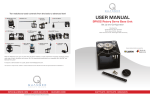
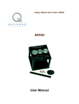
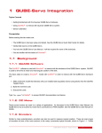
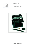
1
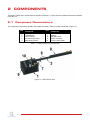
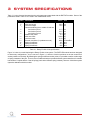
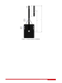
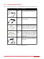
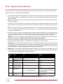
Quanser Rotary Servo
User Manual
SRV02
Quanser Inc.
2011
c 2011 Quanser Inc., All rights reserved.
⃝
Quanser Inc.
119 Spy Court
Markham, Ontario
L3R 5H6
Canada
[email protected]
Phone: 1-905-940-3575
Fax: 1-905-940-3576
Printed in Markham, Ontario.
For more information on the solutions Quanser Inc. offers, please visit the web site at:
http://www.quanser.com
This document and the software described in it are provided subject to a license agreement. Neither the software nor this document may be
used or copied except as specified under the terms of that license agreement. All rights are reserved and no part may be reproduced, stored in
a retrieval system or transmitted in any form or by any means, electronic, mechanical, photocopying, recording, or otherwise, without the prior
written permission of Quanser Inc.
SRV02 User Manual
2
CONTENTS
1
Presentation
1.1
Description
4
4
2
Components
2.1
Component Nomenclature
2.2
Component Description
5
5
6
3
System Specifications
7
4
System Setup
4.1
Assembly
4.2
Changing the Springs
9
9
10
5
Wiring Procedure
5.1
Cable Nomenclature
5.2
Typical Connections
11
12
13
6
Testing and Troubleshooting
6.1
SRV02 Motor and Sensors
6.2
Testing the ROTFLEX Arm Angle Sensor
6.3
Troubleshooting
15
15
15
15
7
Technical Support
16
SRV02 User Manual
v 1.0
1
PRESENTATION
1.1 Description
The Quanser Rotary Flexible Joint module, pictured in Figure 1.1, consists of a rigid beam mounted on a flexible
joint that rotates via a DC motor. The joint deflection is measured using a sensor. This module is designed to mount
to a Quanser rotary servo plant (SRV02). The sensor shaft is aligned with the motor shaft. One end of a rigid link is
mounted to the sensor shaft. The link rotation is counteracted by two extension springs anchored to the solid frame
resulting in an instrumented flexible joint. The spring anchor points are adjustable to three locations to obtain various
stiffness constants. Three types of springs are supplied with the system resulting in a total of 9 possible stiffness
values. The link is also adjustable in length thus allowing for variations in inertia.
Figure 1.1: SRV02 Rotary Flexible Joint Module
This system is similar in nature to the control problems encountered in large geared robot joints where flexibility is
exhibited in the gearbox. The Rotary Flexible Joint is an ideal experiment intended to model a flexible joint on a
robot or spacecraft. This experiment is also useful in the study of vibration analysis and resonance. The SRV02
Rotary Flexible Joint module is equipped with a1024 line optical encoder to sense arm's angular position.
SRV02 User Manual
4
2
COMPONENTS
The Rotary Flexible Joint components are identified in Section 2.1. Some of those components are then described
in Section 2.2.
2.1 Component Nomenclature
The components of the Rotary Flexible Joint module are listed in Table 2.1 below and labeled in Figure 2.1.
ID #
1
2
3
4
5
Component
ROTFLEX base
Thumbscrews
ROTFLEX arm
Arm sensor (Encoder)
Base anchor points
ID #
6
7
8
9
10
Component
Arm anchor points
Springs
Adjustable load
Sensor connector
Pivot on sensor shaft
Table 2.1: Listing of ROTFLEX Components
Figure 2.1: ROTFLEX top view
SRV02 User Manual
v 1.0
2.2 Component Description
2.2.1 Encoder
The ROTFLEX option comes with an optical encoder used to measure the arm's angular position. The model used
is a US Digital Optical Kit Encoder. It offers high resolution (4096 counts in quadrature), and measures the relative
angle of the arm. The internal wiring of the encoder and the 5-pin DIN connector on the ROTFLEX module is
illustrated in Figure 2.2.
Caution: The Encoder sends a digital signal and should be directly connected to a Quanser terminal board using
a standard 5-pin DIN cable. DO NOT connect the encoder signal to the amplifier.
Figure 2.2: Encoder Wiring
SRV02 User Manual
6
3
SYSTEM SPECIFICATIONS
Table 3.1, below, lists and characterizes the main parameters associated with the ROTFLEX module. Some of the
parameters listed in Table 3.1 are used in the mathematical model.
Symbol
L1
L2
d12
d12
d12
m1
m2
Kenc
K1
K2
K3
Description
Module Dimensions
Main arm length
Load arm length
Distance between joint to middle of load arm
Arm Anchor Point 1
Arm Anchor Point 2
Arm Anchor Point 3
Module body mass
Main arm mass
Load arm mass
Encoder resolution (in quadrature mode)
Spring #1 stiffness
Spring #2 stiffness
Spring #3 stiffness
Value
10 x 8 x 5
29.8
15.6
21.0
23.5
26.0
0.3
0.064
0.03
4096
187
313
565
Unit
cm3
cm
cm
cm
cm
cm
kg
kg
kg
Counts/Rev
N/m
N/m
N/m
Table 3.1: Rotary Flexible Joint specifications.
Figure 3.1 below is a model depicting the Rotary Flexible Joint system. The ROTFLEX module has been designed
to allow many configurations. As you can see in Figure 3.1, there are 3 anchor positions on the arm as well as 3
anchor positions on the body. By attaching the springs in different anchor points, it is possible to realize a wide range
of spring constants of the joint. There is also an additional load arm provided with the system that allows for variable
load inertias. Coupled with the 3 sets of springs (each with a different spring constant), there are 112 distinct system
dynamics attainable with this module.
SRV02 User Manual
v 1.0
Figure 3.1: Rotary Flexible Joint Module
SRV02 User Manual
8
4
SYSTEM SETUP
The Rotary Flexible Joint module requires minimal assembly. The ROTFLEX system contains the following components:
• Quanser ROTFLEX module
• 3 sets of springs with differents stiffnesses (in Table 3.1).
• Encoder cable
See Section 4.1 for instructions on how to assemble the Rotary Flexible Joint system. Then, go through the procedure discussed in Section 4.2 to change the springs if desired.
4.1 Assembly
The only assembly required is to mount the ROTFLEX onto the SRV02. Make sure the SRV02 is configured in the
High-Gear configuration, as discussed in [2]. Perform the following 2 steps to assemble the ROTFLEX system:
1. Simply place the ROTFLEX onto the load shaft (middle shaft) and align its pivot with the SRV02 load shaft.
2. Secure the ROTFLEX in place by tightening the two thumbscrews as seen in Figure 4.1 below.
Figure 4.1: Attaching ROTFLEX to the SRV02
SRV02 User Manual
v 1.0
4.2 Changing the Springs
The following is the procedure to properly insert a new set of springs or change spring anchor locations. In order to
maintain proper system dynamics, the springs and anchor positions should be symmetric (i.e. do not use 2 springs
of different stiffness values and make sure both body anchor points are the same).
Note: Using the stiffest set of springs might require extra effort to insert into the anchor points.
1. Take both springs (make sure they are of the same pair) and insert the thumbscrew through the ends of both
springs. Screw the thumbscrew into the desired point on the anchor arm (ID #6) in Figure 2.1.
2. Turn the arm towards you and screw in one side's thumbscrew into the desired base anchor point (ID #5) in
Figure 2.1.
3. Finally, pull the arm toward the other base anchor point (you will feel some resistance from the other spring).
Screw the remaining thumbscrew into the desired base anchor point. Make sure this anchor point is the same
point the other spring is in.
SRV02 User Manual
10
5
WIRING PROCEDURE
The following is a listing of the hardware components used in this experiment:
• Power Amplifier: Quanser VoltPaq-X1, or equivalent.
• Data Acquisition Board: Quanser Q2-USB, Q8-USB, QPID, QPIDe, or equivalent supported DAQ.
• Rotary Servo Plant: Quanser SRV02, SRV02-T, SRV02-E, SRV02-EHR, or SRV02-ET.
• Rotary Flexible Joint: Quanser ROTFLEX Module.
See the references listed at the end of this document for more information on these components. The cables supplied
with the ROTFLEX package are described in Section 5.1 and the procedure to connect the above components is
given in Section 5.2.
SRV02 User Manual
v 1.0
5.1 Cable Nomenclature
Table 5.1, below, provides a description of the standard cables used in the wiring of the ROTFLEX system.
Cable
Type
2xRCA
2xRCA
to
Description
This cable connects an analog output channel
of the data acquisition terminal board to the
power module for proper power amplification.
(a) RCA Cable
4-pin-DIN to
6-pin-DIN
This cable connects the output of the power
module, after amplification, to the desired DC
motor on the servo.
5-pin-stereoDIN
to
5-pin-stereoDIN
This cable carries the encoder signals between an encoder connector and the data
acquisition board (to the encoder counter).
Namely, these signals are: +5 VDC power
supply, ground, channel A, and channel B
6-pin-miniDIN
to
6-pin-miniDIN
This cable carries analog signals (from joystick, plant sensor, etc.) to the amplifier,
where the signals can be either monitored
and/or used by a controller. The cable also
carries a ±12VDC line from the amplifier in
order to power a sensor and/or signal conditioning circuitry.
This cable carries the analog signals, unchanged, from the amplifier to the Digital-ToAnalog input channels on the data acquisition
terminal board.
(b) Motor Cable
(c) Encoder Cable
(d) Analog Cable
5-pin-DIN to
4xRCA
(e) 5-pin-DIN to 4xRCA
Table 5.1: Cable Nomenclature
SRV02 User Manual
12
5.2 Typical Connections
This section describes the typical connections used to connect the ROTFLEX plant to a data-acquisition board and
a power amplifier. The connections are described in detail in the procedure below and summarized in Table 5.2.
Follow these steps to connect the ROTFLEX system:
1. It is assumed that the Quanser DAQ board is already installed as discussed in [3]. If another data-acquisition
device is being used, e.g. NI M-Series board, then go to its corresponding documentation and ensure it is
properly installed.
2. Make sure everything is powered off before making any of these connections. This includes turning off your
PC and the amplifier.
3. Connect one of the connectors on the 2x RCA to 2x RCA cable from the Analog Output Channel #0 on the
terminal board to the Amplifier Command Connector on the Quanser amplifier. See cable #1 shown in Figure
5.1.
4. Connect the 4-pin-stereo-DIN to 6-pin-stereo-DIN from To Load connector on the amplifier to the Motor connector on the SRV02. See connection #2 shown in Figure 5.1. The cable transmits the amplified voltage that
is applied to the SRV02 motor.
5. To use the encoder to measure the load gear angle connect the 5-pin-stereo-DIN to 5-pin-stereo-DIN cable
from the Encoder connector on the SRV02 panel to Encoder Input Channel #0 on the terminal board, as
depicted by connection #3 in Figure 5.1. This carries the load shaft angle measurement by the encoder.
Caution: Any encoder should be directly connected to the Quanser terminal board (or equivalent) using a
standard 5-pin DIN cable. DO NOT connect the encoder cable to the amplifier!
6. Connect the connector on the ROTFLEX directly to Encoder Input Channel #1 on the terminal board, as depicted by connection #4 in Figure 5.1. It carries the arm angle measured by the encoder.
7. [Optional] If you are using the SRV02 potentiometer (i.e., instead of the encoder), connect the To ADC socket
on the amplifier to Analog Input Channels #0-1 on the terminal board using the 5-pin-DIN to 4xRCA cable, as
illustrated in Figure 5.1 by connection #5. The RCA side of the cable is labeled with the channels. Note that
the cable with label "1" (yellow connector) goes to Analog Input Channel #0.
8. [Optional] If you are using the SRV02 potentiometer, connect the S1 & S2 connector on the SRV02 to the S1
& S2 socket on the amplifier using the 6-pin-mini-DIN to 6-pin-mini-DIN cable. See connection #6 in Figure
5.1. This carries the voltage signal from the potentiometer.
Cable
#
1
2
3
4
5
6
From
To
Signal
Terminal
Board:
Analog Output #0
Amplifier ''To Load''
Connector
Terminal
Board:
Encoder Input #0
Terminal
Board:
Encoder Input #1
Amplifier ''To ADC''
connector
Amplifier ''Command'' Conector
Control signal to the amplifier.
SRV02 ''Motor'' Connector
Amplifier ''S1 & S2''
connector
SRV02 ''S1 & S2'' connector
Power leads to the SRV02 DC
motor.
Servo load shaft angle measurement.
Flexibe joint angle measurement.
Carries the analog signals connected to the S1 & S2 connectors on the amplifier to the dataacquisition board.
Potentiometer load shaft angle
measurement.
SRV02 ''Encoder'' Connector
ROTFLEX ''Encoder'' Connector
Terminal Board:
• S1 to Analog Input #0
Table 5.2: ROTFLEX system wiring summary
SRV02 User Manual
v 1.0
Figure 5.1: SRV02 and ROTFLEX Module Wiring Diagram
SRV02 User Manual
14
6
TESTING AND TROUBLESHOOTING
This section describes some functional tests to determine if your ROTFLEX is operating normally. It is assumed that
the system is connected as described in the Section 5.2, above. To carry out these tests, it is preferable if the user
can use a software such as QUARCr or LabVIEWr to read sensor measurements and feed voltages to the motor.
See Reference [1] to learn how to interface the SRV02 with QUARC. Alternatively, these tests can be performed
with a signal generator and an oscilloscope.
6.1 SRV02 Motor and Sensors
Please refer to [2] for information on testing and troubleshooting the SRV02 separately.
6.2 Testing the ROTFLEX Arm Angle Sensor
Follow this procedure to test the ROTFLEX encoder:
1. Measure Encoder Input Channel #1 using, for instance, the QUARC software.
2. Rotate the ROTFLEX arm, component #3 in Figure 2.1, slightly back-and-forth and verify that your are obtaining
a reading.
3. If it is measuring, make sure it is reading the correct angle. For example, rotate the arm 30 degrees and ensure
you are reading 30 degrees, which is about 341 counts in quadrature mode, in the software.
Note: Some data acquisition systems do not measure in quadrature and, in this case, one-quarter of the expected counts are received, i.e. 1024 counts. In addition, some data acquisition systems measure in quadrature but increment the count by 0.25 (as opposed to having an integer number of counts). Make sure the
details of the data-acquisition system being used is known. The counters on the Quanser DAQ boards measure in quadrature and therefore a total of four times the number of encoder lines per rotation, e.g. a 1024-line
encoder results in 4096 integer counts for every full rotation.
6.3 Troubleshooting
Follow the steps below if the encoder on the ROTFLEX model is not measuring properly: If the encoder is not
measuring properly, go through this procedure:
• Check that the data-acquisition board is functional, e.g. ensure it is properly connected, that the fuse is not
burnt.
• Check that both the A and B channels from the encoder are properly generated and fed to the data-acquisition
device. Using an oscilloscope, there should be two square waves, signals A and B, with a phase shift of 90
degrees. If this is not observed then the encoder may be damaged and need to be replaced. Please see
Section 7 for information on contacting Quanser for technical support.
SRV02 User Manual
v 1.0
7
TECHNICAL SUPPORT
To obtain support from Quanser, go to http://www.quanser.com/ and click on the Tech Support link. Fill in the form
with all the requested software and hardware information as well as a description of the problem encountered.
Also, make sure your e-mail address and telephone number are included. Submit the form and a technical support
representative will contact you.
SRV02 User Manual
16
REFERENCES
[1] Quanser Inc. SRV02 QUARC Integration, 2008.
[2] Quanser Inc. SRV02 User Manual, 2009.
[3] Quanser Inc. Q2-USB Data-Acquisition System User's Guide, 2010.
SRV02 User Manual
v 1.0