1
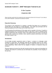
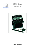
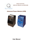
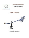
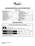
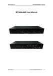
Linear Motion Servo Plant: AMD-2
Active Mass Damper - Two Floors
(AMD-2)
User Manual
AMD-2 User Manual
Table of Contents
1. Active Mass Damper – Two-Floor Structure (AMD-2) Presentation.................................1
1.1. AMD-2: System Description........................................................................................1
1.2. AMD-2: Control Challenge.........................................................................................2
2. References............................................................................................................................2
3. AMD-2 System Description................................................................................................3
3.1. Component Nomenclature...........................................................................................3
3.2. Component Description...............................................................................................5
3.2.1. Flexible Structure (Components #18 And #19)...................................................5
3.2.2. Cart Rack (Components #2, #3, and #5)..............................................................5
3.2.3. Floor Accelerometers (Components # 23 And #25).............................................6
3.2.4. Cart DC Motor (Component #9)..........................................................................6
3.2.5. Cart Planetary Gearbox (Component #17)...........................................................7
3.2.6. IP01-Based Cart Potentiometer............................................................................7
3.2.7. IP02-Based Cart Encoder (Component #10)........................................................7
4. AMD-2 Model Parameters...................................................................................................9
5. Wiring Procedure For The AMD-2 System.......................................................................11
5.1. Cable Nomenclature...................................................................................................11
5.2. Hardware Requirements.............................................................................................13
5.3. Typical Connections For The AMD-2 System...........................................................14
5.3.1. Wiring Of The Cart DC Motor Power Line.......................................................14
5.3.2. Wiring Of The Feedback Signals.......................................................................14
5.3.3. AMD-2 Wiring Summary...................................................................................16
6. Setting Up the AMD-2 Plant.............................................................................................17
7. Obtaining Support..............................................................................................................17
Appendix A. Cart DC Motor Specification Sheet.................................................................18
Appendix B. Cart Planetary Gearhead Specification Sheet...................................................19
Appendix C. IP01-Based Cart Potentiometer Specification Sheet........................................20
Appendix D. IP02-Based Cart Encoder Specification Sheet.................................................21
Document Number: 570 ! Revision: 02 ! Page: i
AMD-2 User Manual
1. Active Mass Damper – Two-Floor
Structure (AMD-2) Presentation
1.1. AMD-2: System Description
The typical Active Mass Damper – Two-Floor structure
(AMD-2) plant is depicted in Figure 1. The AMD-2 plant
is a bench-scale model to emulate a building controlled by
an Active Mass Damper (AMD). The plant consists of a
two-story building-like structure on top of which a linear
cart (i.e. active mass) is driven by a rack and pinion
mechanism. The first and second floors are each instrumented with an accelerometer measuring the accelerations
of the middle and top floors, respectively, relative to
ground. The structure frame is made of steel and is flexible along its facade. Such a scaled structure has been designed to study critical aspects of structural control implementations.
The top (a.k.a. roof) of the structure accommodates a rack
and a shaft designed to work with an IP01- or IP02- type
of linear cart, which thus constitutes the controllable mass
at the top of the structure. The cart is free to move along
in the same direction as the structure. Specifically, it is a
precisely machined solid aluminum cart which is driven
by a high quality DC motor equipped with a planetary
gearbox. The cart slides along a stainless steel shaft using
linear bearings. When the motor turns, the torque created
at the output shaft is translated, through the rack and
pinion mechanism, to a linear force (i.e. control force)
which results in the cart's motion. The cart position is
directly measured using either a potentiometer (for the
IP01-based cart) or an encoder (for the IP02-based cart)
whose shaft meshes with the track via an additional
Figure 1 AMD-2 System
pinion. Moreover, two masses are available for attachment
to
the cart, so that it has more inertia to absorb the structure's vibrations. These two weights
can be used or removed for assessing the robustness of the controller and the effects of
Document Number: 570 ! Revision: 02 ! Page: 1
AMD-2 User Manual
variations in parameters. For more details regarding the IP01 and IP02 linear servo plants
and their applications, please review Reference [1].
Different building/linear cart configurations can be constructed, depending for instance on
the location of the cart in the structure. Also several Quanser's single-story AMD buildings
can be connected either in series or in parallel. Additionally, the flexible system can also be
excited using the Quanser Shake Table II, as described in Reference [2]. Of course, those
different combinations allow for Multi-Input-Multi-Ouput (MIMO) experiments.
1.2. AMD-2: Control Challenge
The AMD-2 plant forms an autonomous servo system. The challenge in designing a control
system that dampens out the vibrations in the two-story building-like structure is that the
deflections of both first and second floors (or horizontal displacement) are NOT measured.
Instead, the structure's feedback sensors are two accelerometers mounted on the AMD-2's
middle and top floors. The only other sensor that is available is to measure the linear cart
position. The only input to the AMD-2 system is the cart motor voltage.
In order to dampen out the vibrations in the AMD-2 flexible structure, the system is
supplied with a state-feedback controller based on a full-order observer. The closed-loop
control scheme drives the active mass (i.e. linear cart) by taking into account the actual cart
position and both floor acceleration feedback signals. Of course, you may design any other
controller you wish. The complete mathematical modelling and system parameters are
provided to streamline the implementation of the control theory of your choice.
2. References
[1] IP01 and IP02 User Manual.
[2] Shake Table II Experiment Manual.
Document Number: 570 ! Revision: 02 ! Page: 2
AMD-2 User Manual
3. AMD-2 System Description
3.1. Component Nomenclature
As a quick nomenclature, Table 1, below, provides a list of all the principal elements
composing the Active Mass Damper – Two-Floor system (AMD-2). Every element is
located and identified, through a unique identification (ID) number, on the AMD-2 plant
represented in Figures 2, 3, 4, and 5, below.
ID #
Description
Description
ID #
1
AMD Cart
2
Stainless Steel Shaft
3
Track
4
Linear Bearing
5
Rack End Plate
6
Rack Set Screw: (7/64)"
7
Cart Load Weight
8
Cart Load Weight Set Screw: (3/32)"
9
Cart DC Motor
10
Cart Encoder
11
Cart Motor Pinion
12
Cart Position Pinion
13
Cart Motor Pinion Shaft
14
Cart Position Pinion Shaft
15
Cart Motor Connector
16
Cart Encoder Connector
17
Cart Planetary Gearbox
18
First Floor Flexible Structure
19
Second Floor Flexible Structure
20
Ground Floor
21
First Floor
22
Second Floor
23
First Floor Accelerometer
24
First Floor Accelerometer Connector
25
Second Floor Accelerometer
26
Second Floor Accelerometer Connector
27
Accelerometer Offset Potentiometer
28
Accelerometer Gain Potentiometer
Table 1 AMD-2 Component Nomenclature
Document Number: 570 ! Revision: 02 ! Page: 3
AMD-2 User Manual
Figure 2 AMD-2 Cart: Front View
Figure 4 AMD-2 IP02-Type Cart: Bottom View
Figure 5 AMD-2 Accelerometer: Bottom View
Figure 3 AMD-2 Structure: Front View
Document Number: 570 ! Revision: 02 ! Page: 4
AMD-2 User Manual
3.2. Component Description
3.2.1. Flexible Structure (Components #18 And #19)
The Active Mass Damper – Two-Floor (AMD-2) structure is made of two identical singlestory modules connected on top of each other (i.e. in series). Each single-story structural
module consists of two vertical steel beams. Each steel column has a section of 1.75 by
108.1 millimeters and a mass of 0.240 kilograms. Each single-story frame external
dimensions are shown in Table 2, below.
Description
Value
Unit
Flexible Module Height
0.50
m
Flexible Module Length
0.32
m
Flexible Module Depth
0.11
m
Table 2 Single-Story Module Dimensions
The resulting overall dimensions for the AMD-2 structure are shown in Table 3, below.
Description
Value
Unit
AMD-2 Structure Height
1.00
m
AMD-2 Structure Length
0.32
m
AMD-2 Structure Depth
0.11
m
Table 3 AMD-2 Overall Dimensions
3.2.2. Cart Rack (Components #2, #3, and #5)
Table 4, below, characterizes the overall dimensions of the cart rack used in the Active
Mass Damper – Two-Floor (AMD-2) system.
Description
Value
Unit
Overall Cart Rack Length
0.31
m
Overall Cart Rack Height
0.13
m
Overall Cart Rack Depth
0.11
m
Table 4 AMD-2 Cart Rack Overall Dimensions
Document Number: 570 ! Revision: 02 ! Page: 5
AMD-2 User Manual
3.2.3. Floor Accelerometers (Components # 23 And #25)
Each floor of the building-like structure is equipped with a capacitive DC accelerometer
with full-scale range of ±5 g. It consists of a single-chip accelerometer with signal conditioning. The AMD-2 accelerometers are calibrated in-house to generate 1 Volt per 9.81 m/s2
(i.e. 1 V/g), as characterized by the accelerometer sensitivity shown in Table 5, on page 10.
The accelerometer has the capability to measure both AC/dynamic accelerations (e.g. vibrations) and DC/static accelerations (e.g. gravity). The arrow represented on the accelerometer, and depicted in Figure 5, shows the positive direction of the AC acceleration sensor
measurement on its axis of sensitivity. To best measure the AMD-2 floor vibration, both accelerometers are mounted such their sensitive axes are longitudinal to the structure. Quickly
pushing each floor of the AMD-2 plant towards the right, when facing the structure, should
result in an initial positive acceleration voltage.
Although both AMD-2 accelerometers have already been calibrated at the factory, the signal
conditioning circuit properties may vary depending on the external conditions (e.g. humidity, temperature). Therefore, you may want to adjust each accelerometer's Offset potentiometer (shown as component #27 in Figure 5) such that it reads approximately zero Volts
with zero acceleration (i.e. sensor resting flat or horizontal). Likewise, each accelerometer's
Gain potentiometer (shown as component #28 in Figure 5) can be adjusted to read minus
one Volts when the sensor is resting vertically on its right side with the arrow pointing
downwards.
3.2.4. Cart DC Motor (Component #9)
The AMD-2 cart incorporates a Faulhaber Coreless DC Motor (2338S006), as represented
in Figures 2 and 4 by component #9. This model is a high efficiency low inductance motor
resulting in a much faster response than a conventional DC motor. The complete specification sheet of the motor is included in Appendix A.
CAUTION:
High Frequency signals applied to a motor will eventually damage the gearbox and/or the
motor brushes. The most likely source for high frequency noise is derivative feedback. If the
derivative gain is too high, a noisy voltage will be fed into the motor. To protect your motor,
you should always band limit your signal (especially derivative feedback) to a value of
50Hz.
Document Number: 570 ! Revision: 02 ! Page: 6
AMD-2 User Manual
3.2.5. Cart Planetary Gearbox (Component #17)
The AMD-2 cart DC motor is coupled to a Faulhaber Planetary Gearhead Series 23/1, as
represented in Figures 2 and 4 by component #17. Its reduction ratio is 3.71:1. The complete
specification sheet of the planetary gearbox is included in Appendix B.
3.2.6. IP01-Based Cart Potentiometer
If the AMD-2 cart is based on the IP01 cart, described in Reference [1], its linear position is
sensed by a 10-turn black potentiometer, namely the Vishay Spectrol model 534-1-1-103.
The cart potentiometer is connected to a ±12 Volt DC power supply through two bias resistors of 7.15 kΩ each. The total output range of the cart position potentiometer results to be
±5V over its 10 complete turns (i.e. 3600 degrees). The main specifications of the IP01based AMD-2 cart potentiometer are included in Appendix C.
Refer to Table 5, on page 10, for the resulting potentiometer sensitivity. Pushing manually
the AMD-2 cart towards the right side of the track, when facing it, should result in a positive change in the cart position potentiometer voltage. Likewise, pushing the cart towards
the left side of the track, when facing it, should result in a decreasing cart position potentiometer voltage.
3.2.7. IP02-Based Cart Encoder (Component #10)
If the AMD-2 cart is based on the IP02 cart, described in Reference [1], its linear position is
measured with one optical encoder, which is represented in Figure 4 by component #10. The
encoder model used in the AMD-2 cart is a US Digital S1 single-ended optical shaft encoder. It offers a high resolution of 4096 counts per revolution (i.e. 1024 lines per revolution with two channels in quadrature).
The complete specification sheet of the S1 optical shaft encoder is included in Appendix D.
The internal wiring diagram of the cart encoder is depicted in Figure 6. The standard 5-pin
DIN connector, shown in Figure 6, is also pictured as component #16 in Figure 2.
Document Number: 570 ! Revision: 02 ! Page: 7
AMD-2 User Manual
Figure 6 Cart Encoder Wiring
Refer to Table 5, on page 10, for the resulting encoder resolution. Pushing manually the
AMD-2 cart towards the right side of the track, when facing it, should result in a positive
change in the cart position. Likewise, pushing the cart towards the left side of the track,
when facing it, should result in a decreasing cart position.
Document Number: 570 ! Revision: 02 ! Page: 8
AMD-2 User Manual
4. AMD-2 Model Parameters
Table 5, below, lists and characterizes the main parameters (e.g. mechanical and electrical
specifications, convertion factors) associated with the Active Mass Damper – Two-Floor
(AMD-2) plant. Some of these parameters can be used for mathematical modelling of the
AMD-2 system as well as to obtain the structure-plus-cart's Equations Of Motion (EOM).
Symbol
Description
Value
Unit
Hf1
First Floor Height
0.502
m
Hf2
Second (i.e. Top) Floor Height
1.035
m
Ms
Structure Total Mass (With No Rack And No Cart)
3.300
kg
Mf1
First Floor Mass
1.160
kg
Mf2
Second Floor Mass (With Rack)
1.380
kg
Mr
Rack Mass
0.700
kg
Mc
Cart Mass (With Two Weights)
0.650
kg
Mw
Cart Weight Mass
0.130
kg
Kf1
First Floor Linear Stiffness Constant (Relative To
The Ground)
500
N/m
Kf2
Second Floor Linear Stiffness Constant (Relative
To The First Floor)
500
N/m
Tc
Cart Travel (i.e. Stroke)
0.19
m
Pr
Rack Pitch
1.664E-003
m/tooth
Vnom
Cart Motor Nominal Input Voltage
6.0
V
fvmax
Cart Motor Input Voltage Maximum Frequency
50
Hz
Rm
Cart Motor Armature Resistance
2.6
Ω
Lm
Cart Motor Armature Inductance
0.18
mH
Kt
Cart Motor Torque Constant
0.00767
N.m/A
ηm
Cart Motor Efficiency
100
%
Km
Cart Back-ElectroMotive-Force (EMF) Constant
0.00767
V.s/rad
Jm
Cart Rotor Moment of Inertia
3.90E-007
kg.m2
Document Number: 570 ! Revision: 02 ! Page: 9
AMD-2 User Manual
Symbol
Description
Value
Unit
N.s/m
Beq
Equivalent Viscous Damping Coefficient, as seen
at the Motor Pinion
3.0
Kg
Cart Planetary Gearbox Gear Ratio
3.71
ηg
Cart Planetary Gearbox Efficiency
100
%
rmp
Cart Motor Pinion Radius
6.35E-003
m
Nmp
Cart Motor Pinion Number of Teeth
rpp
Cart Position Pinion Radius
Npp
Cart Position Pinion Number of Teeth
KEC
Cart Encoder Resolution (if IP02-Based)
KPC
Cart Potentiometer Sensitivity (if IP01-Based)
KACC
Floor Accelerometer Sensitivity
24
1.48E-002
m
56
2.275E-005
m/count
0.0931
m/V
9.81
m/s2/V
Table 5 AMD-2 System Paremeters
Document Number: 570 ! Revision: 02 ! Page: 10
AMD-2 User Manual
5. Wiring Procedure For The AMD-2
System
This section describes the standard wiring procedure for the Active Mass Damper – TwoFloor (AMD-2) plant.
The following hardware, accompanying the AMD-2, is assumed:
Power Amplifier:
Quanser UPM 1503 / UPM 2405 or equivalent.
Data Acquisition Card:
Quanser Q8 / MultiQ-PCI / MultiQ-3, or one of the
National Instruments E-Series cards, or equivalent.
5.1. Cable Nomenclature
Table 6, below, provides a description of the standard cables used in the wiring of the
AMD-2.
Cable
Designation
Description
5-pin-DIN
to
RCA
This cable connects an analog
output of the data acquisition
terminal board to the power
module for proper power amplification.
4-pin-DIN
to
6-pin-DIN
This cable connects the output of
the power module, after amplification, to the desired actuator
(e.g. cart motor). One end of this
cable contains a resistor that sets
the amplification gain (e.g. 1, 3,
5).
Figure 7 "From Digital-To-Analog" Cable
Figure 8 "To Load" Cable Of Gain 1
Document Number: 570 ! Revision: 02 ! Page: 11
AMD-2 User Manual
Cable
Designation
Description
5-pin-stereoDIN
to
5-pin-stereoDIN
This cable carries the encoder
signals between the encoder connector and the data acquisition
board (to the encoder counter).
Namely, these signals are:
+5VDC power supply, ground,
channel A, and channel B.
6-pin-miniDIN
to
6-pin-miniDIN
This cable carries analog signals
from one or two plant sensors
(e.g. floor accelerometer, cart
potentiometer) to the UPM,
where the signals can be either
monitored and/or used by an
analog controller. The cable also
carries a ±12VDC line from the
UPM in order to power a sensor
and/or signal conditioning circuitry.
5-pin-DIN
to
4xRCA
This cable carries the analog signals, previously taken from the
plant sensors (e.g. floor accelerometer, cart potentiometer), unchanged, from the UPM to the
Digital-To-Analog input channels on the data acquisition terminal board.
Figure 9 "Encoder" Cable
Figure 10 "From Analog Sensors" Cable
Figure 11 "To Analog-To-Digital" Cable
Table 6 Cable Nomenclature
The connectors are also fully compatible with our quick-connect system enabling you to
switch from one experiment to another quickly and efficiently.
Document Number: 570 ! Revision: 02 ! Page: 12
AMD-2 User Manual
5.2. Hardware Requirements
Figures 12, 13, 14, and 15, below, show, respectively, the top of the AMD-2, the Q8
Terminal Board, the bottom of the AMD-2 system, and the Universal Power Module (e.g.
UPM1503), all connected with the necessary cabling to interface to and use the AMD-2
plant.
Figure 13 Q8 Terminal Board Connections
Figure 12 AMD-2 Top Connections
Figure 15 Universal Power Module: UPM1503
Figure 14 AMD-2 Bottom Connections
Document Number: 570 ! Revision: 02 ! Page: 13
AMD-2 User Manual
Together with the power supply for the amplifier, all Quanser power modules are equipped
with a 1-ampere ±12-volt regulated DC power supply for signal conditioning of external
analog sensors.
5.3. Typical Connections For The AMD-2 System
5.3.1. Wiring Of The Cart DC Motor Power Line
The "power" line wiring of the AMD-2 cart DC motor consists of two connections, as
described below:
1. Connect the "From Digital-To-Analog" Cable – Cable #1:
The "From Digital-To-Analog" cable is the 5-pin-DIN-to-RCA cable described in Table
6 and shown in Figure 7. Connect the RCA end of this cable to the Analog Output 0
(i.e. DAC # 0) of your data acquisition card terminal board and its 5-pin-DIN connector
to the socket labelled "From D/A" on the Quanser Universal Power Module (UPM).
These two connections are illustrated by cable #1 in Figures 13 and 15, above.
2. Connect the "To Load" Cable Of Gain 1 – Cable #2:
The "To Load" cable of gain 1 is the 4-pin-DIN-to-6-pin-DIN cable described in Table 6
and shown in Figure 8. First, connect the cable 4-pin-DIN connector to the AMD-2 cart
Motor Connector, which is shown as component #15 in Figure 2. Then connect the
cable 6-pin-DIN connector to the UPM socket labelled "To Load". These two
connections are illustrated by cable #2 in Figures 12 and 15, above.
5.3.2. Wiring Of The Feedback Signals
The AMD-2 system provides three feedback signals. First, the linear cart position signal is
produced using either a potentiometer, if the cart is based on the IP01, or an encoder, if the
cart is based on the IP02. Second and last, the acceleration signals of the structure first and
second floors are provided by using an accelerometer on each floor. To connect these
feedback sensors, follow the steps described below:
1. Connect the "From Analog Sensors" Position Cable – Cable #4:
In case of an IP01-based cart, the position potentiometer has to be connected. The "From
Analog Sensors" cable is the 6-pin-mini-DIN-to-6-pin-mini-DIN cable described in
Table 6 and shown in Figure 10. First connect one end of the cable to the IP01-based
cart's S1 & S2 Connector, as shown in Reference [1]. Then connect the cable's other end
Document Number: 570 ! Revision: 02 ! Page: 14
AMD-2 User Manual
to the UPM socket labelled "S1 & S2", which is contained inside the UPM "From
Analog Sensors" front panel. This connection to the UPM is illustrated by cable #4 in
Figure 15, above.
2. Connect the "Encoder" Position Cable – Cable #7:
In case of an IP02-based cart, the position encoder has to be connected. The "Encoder"
cable is the 5-pin-stereo-DIN-to-5-pin-stereo-DIN cable described in Table 6 and shown
in Figure 9. First connect one end of the cable to the IP02-based cart's Encoder
Connector, which is shown as component #16 in Figure 2. Then connect the cable's
other end to the Encoder Input 0 on your data acquisition card terminal board. These
two connections are illustrated by cable #7 in Figures 12 and 13, above.
CAUTION:
Any encoder should be directly connected to the Quanser terminal board (or equivalent)
using a standard 5-pin DIN cable. DO NOT connect the encoder cable to the UPM!
3. Connect the "From Analog Sensors" First Floor Acceleration Cable – Cable #5:
The "From Analog Sensors" cable is the 6-pin-mini-DIN-to-6-pin-mini-DIN cable
described in Table 6 and shown in Figure 10. First connect one end of the cable to the
First Floor Accelerometer Connector, which is located at the back of the AMD-2's first
floor as shown by component #24 in Figures 3 and 5, above. Then connect the cable's
other end to the UPM socket labelled "S3", which is contained inside the UPM "From
Analog Sensors" front panel. These connections are illustrated by cable #5 in Figures 14
and 15, above.
4. Connect the "From Analog Sensors" Second Floor Acceleration Cable – Cable #6:
The "From Analog Sensors" cable is the 6-pin-mini-DIN-to-6-pin-mini-DIN cable
described in Table 6 and shown in Figure 10. First connect one end of the cable to the
Second Floor Accelerometer Connector, which is located at the back of the AMD-2's
second floor as shown by component #26 in Figure 3, above. Then connect the cable's
other end to the UPM socket labelled "S4", which is contained inside the UPM "From
Analog Sensors" front panel. These connections are illustrated by cable #6 in Figures 12
and 15, above.
5. Connect the "To Analog-To-Digital" Cable – Cable #3:
The "To Analog-To-Digital" cable is the 5-pin-DIN-to-4xRCA cable described in Table
6 and shown in Figure 11. First, connect the cable 5-pin-DIN connector to the UPM
socket labelled "To A/D", as illustrated by cable #3 in Figure 15, above. The other end
of the cable is split into four RCA connectors, each one labelled with a single digit
ranging from one to four. This numbering corresponds to the four possible analog sensor
signals passing through the UPM, namely S1, S2, S3 and S4. In order for the analog
Document Number: 570 ! Revision: 02 ! Page: 15
AMD-2 User Manual
signals to be used in software, you should then connect all four RCA connectors to the
first four analog input channels of your data acquisition card terminal board. Specifically,
connect S1 to Analog Input 0, S2 to Analog Input 1, S3 to Analog Input 2, and S4 to
Analog Input 3, as illustrated by cable #3 in Figure 13, above.
In other words, the AMD-2 cart position is either sensed using A/D #0 through the UPM
analog channel S1 if the cart has a potentiometer (i.e. based on the IP01), or using Encoder
Channel #0 if the cart has an encoder (i.e. based on the IP02). The flexible structure top
floor's acceleration is measured using A/D #3 through the UPM analog channel S4.
5.3.3. AMD-2 Wiring Summary
Table 7, below, sums up the electrical connections necessary to run the AMD-2 system.
Cable #
From
To
Signal
1
DAC #0
UPM "From D/A" Control signal to the UPM.
2
UPM
"To Load"
AMD-2
Power leads to the cart DC
"Motor Connector" motor.
3
UPM
"To A/D"
Terminal Board:
S1 to ADC #0
S3 to ADC #2
S4 to ADC #3
IP01-based cart potentiometer,
if present, and both
accelerometer signals to the
data acquisition terminal board,
through the UPM.
4
AMD-2 Cart
"S1 & S2 Connector"
UPM "S1 & S2"
IP01-based cart position
feedback signal, if necessary, to
the UPM.
5
AMD-2 First Floor
"Accelerometer
Connector"
UPM "S3"
First floor accelerometer
feedback signal to the UPM.
6
AMD-2 Second Floor
"Accelerometer
Connector"
UPM "S4"
Second floor accelerometer
feedback signal to the UPM.
7
AMD-2 Cart
"Encoder Connector"
Terminal Board: IP02-based cart position
Encoder Channel feedback signal, if necessary, to
#0
the data acquisition card.
Document Number: 570 ! Revision: 02 ! Page: 16
AMD-2 User Manual
Cable #
From
To
8
Power Supply Outlet
UPM Power
Socket
Signal
UPM Power Supply.
Table 7 AMD-2 Wiring Summary
6. Setting Up the AMD-2 Plant
For safety and proper operation, the AMD-2 base plate (a.k.a. "ground" floor) should be
rigidly clamped or screwed down to a table or workbench. As an example, a C-clamp is
depicted in Figure 14, above, as represented by component #9.
7. Obtaining Support
Note that a support contract may be required to obtain technical support. To obtain
support from Quanser, go to http://www.quanser.com and click on the Tech Support link.
Fill in the form with all requested software version and hardware information and a description of the problem encountered. Submit the form. Be sure to include your email address
and a telephone number where you can be reached. A qualified technical support person
will contact you.
Document Number: 570 ! Revision: 02 ! Page: 17
AMD-2 User Manual
Appendix A. Cart DC Motor
Specification Sheet
Document Number: 570 ! Revision: 02 ! Page: 18
AMD-2 User Manual
Appendix B. Cart Planetary Gearhead
Specification Sheet
Document Number: 570 ! Revision: 02 ! Page: 19
AMD-2 User Manual
Appendix C. IP01-Based Cart
Potentiometer Specification Sheet
Document Number: 570 ! Revision: 02 ! Page: 20
AMD-2 User Manual
Appendix D. IP02-Based Cart Encoder
Specification Sheet
Document Number: 570 ! Revision: 02 ! Page: 21