1
IQAN Software G32
USER MANUAL
User manual, IQAN Software G32
License
Software User Agreement
Important-please read carefully before use of the Software.
Your use of this computer program is subject to the terms and conditions of the following Software User Agreement. If you do not wish to accept these terms and conditions, do not install or
use this Software and please return this Software to the place you obtained it for refund.
License agreement, restrictions on use
Use
This is a license agreement between you (the entity to whom this software is provided) and
Parker Hannifin Corporation ("Licensor"). This agreement permits you to Use each program
furnished directly or indirectly from Licensor, either by Licensor or its authorized distributors
("Distributors") including any Copies thereof and any supporting materials and any related
updated programs or program portions ("Software"). The term "Copies" means any duplications, reproductions, transcriptions of any Software, either in whole or in part and by any
means whatsoever including electronic, mechanical, and manual processes. The term "Use"
means copying any portion of any Software or using any Software, but only in connection with
the analysis, specification, use, installation, repair, sale of products through Licensor or its Distributors.
Restrictions
You will have a non-transferable and non-exclusive right to Use the Software. You may make
Copies of the Software provided that any such Copies are made solely for your Use or for
archival or back-up and no other purposes. No right to Use, print, copy of display the Software,
in whole or in part, is granted except as expressly provided in this agreement. You will not
reverse engineer, disassemble or decompile the Software. You agree to reproduce and include
any and all copyright notices, software user agreements notices and terms and conditions,
trademarks and other legends in and on every Copy of the Software.
User manual, IQAN Software G32
Ownership
Title and ownership of the Software and Copies thereof shall at all times exclusively remain in
Licensor or its designee. You will obtain no greater right in and to the Software than a right in
the nature of the License limited to the Use of any such Software and subject to compliance
with all of the terms and conditions contained in this Agreement. To the extent that the Software becomes deliverable under any U.S. Government funded prime contract or subcontract,
(i) you acknowledge and agree that this Software represent "commercial computer software" as
defined in the DoD Federal Acquisitions Regulation Supplement (DFARS) § 525.227-7014
(a)(I), and (ii) the Goverment´s right in connection with the Software will be limited in accordance with the terms and conditions of this Agreement consistent with the policies stated in
DFARS Subpart 227.7202.
Modifications
Modifications or enhancements made by Licensor to any Software from time to time may be
made available to you at the sole option of Licensor or its Distributors. If the Software is modified by you or merged into other program materials processed or used by solely by you, Licensor and its Distributors shall not have any liability or incur any expense or be affected in any
way by any such modification or merger, even if such modification or merger results in the formation of an updated or new work. Rather, such Software, in its modified or merged form,
shall continue at all times to be the sole and exclusive property of Licensor and shall be subject
to all provisions of this Agreement.
Limited warranty
Limited warranty
Licensor warrants that (a) the original Software will perform substantially in accordance with
the accompanying written materials for a period of ninety (90) days from the date of receipt;
and (b) any hardware accompanying the Software will be free from defects in materials and
workmanship under normal use and service for a period of one (1) year from receipt date. Any
implied warranties on the Software and the hardware are limited only to ninety (90) days and
one (1) year respectively. The limited warranty applies to the original Software and not to any
copies made by you or others from the original Software or copies thereof.
User manual, IQAN Software G32
Customer remedies
Licensor´s entire liability and your exclusive remedy shall be, at Licensor´s option either (a)
return of the price paid or (b) repair or replacement of the Software or hardware that does not
meet Licensor´s limited warranty and that is returned to the Licensor with a copy of your
receipt. The limited warranty is void if failure of the Software or hardware has resulted from
accident, abuse, or misapplication of the original hardware and Software only and in no case
shall the limited warranty apply to any copies of the original Software. Any replacement Software shall be warranted for the remainder of the original warranty period or for thirty (30)
days, whichever is longer.
No other warranties
Licensor disclaims all other warranties, either express or implied, including but not limited to
implied warranties of merchantability and fitness for a particular purpose, with respect to the
Software, any accompanying written material, any accompanying hardware, and any services
for any of the foregoing.
No other liability
In no event will Licensor or its agents or suppliers or Distributors be liable for any direct or
indirect damages whatsoever (including without limitation, damages for negligence, strict liability, breach of contract, loss of business profits, business interruption, loss of business information, or pecuniary loss) arising out of the use of, or inability to use or failure to deliver the
Software or any defects therein, even if the Licensor has been advised of the possibility of such
damages. In no event shall the aggregate liability of Licensor, its agents, suppliers and distributors exceed an amount equal to the price paid for the Software license.
ATTENTION
If you do not accept the terms and conditions of this license do not install or use the Software.
User manual, IQAN Software G32
Contents
Contents
1
Introduction . . . . . . . . . . . . . . . . . . . . . . . . . . . . . . . . . . . . . . . . . . . . . . . . . . . . 15
2
Installation . . . . . . . . . . . . . . . . . . . . . . . . . . . . . . . . . . . . . . . . . . . . . . . . . . . . . 16
Installing IQANdevelop . . . . . . . . . . . . . . . . . . . . . . . . . . . . . . . . . . . . . . . . . . . . . 16
3
Safety regulations . . . . . . . . . . . . . . . . . . . . . . . . . . . . . . . . . . . . . . . . . . . . . . . 17
Warning symbol . . . . . . . . . . . . . . . . . . . . . . . . . . . . . . . . . . . . . . . . . . . . . . . . . . . . 17
Emergency stop . . . . . . . . . . . . . . . . . . . . . . . . . . . . . . . . . . . . . . . . . . . . . . . . . . . . 17
Testing the application for machine . . . . . . . . . . . . . . . . . . . . . . . . . . . . . . . . . 17
Sending data to the IQAN system . . . . . . . . . . . . . . . . . . . . . . . . . . . . . . . . . . . 18
Downloading via modem . . . . . . . . . . . . . . . . . . . . . . . . . . . . . . . . . . . . . . . . . . . 18
Protecting the application . . . . . . . . . . . . . . . . . . . . . . . . . . . . . . . . . . . . . . . . . . 18
4
Getting started . . . . . . . . . . . . . . . . . . . . . . . . . . . . . . . . . . . . . . . . . . . . . . . . . . 19
Starting IQANdevelop . . . . . . . . . . . . . . . . . . . . . . . . . . . . . . . . . . . . . . . . . . . . . . 20
Building an application in IQANdevelop . . . . . . . . . . . . . . . . . . . . . . . . . . . . . 21
System overview . . . . . . . . . . . . . . . . . . . . . . . . . . . . . . . . . . . . . . . . . . . . . . . 22
Alternating between block diagrams . . . . . . . . . . . . . . . . . . . . . . . . . . . 22
Naming and saving the application . . . . . . . . . . . . . . . . . . . . . . . . . . . . . . . . . 23
Application information . . . . . . . . . . . . . . . . . . . . . . . . . . . . . . . . . . . . . . . . 23
Save application . . . . . . . . . . . . . . . . . . . . . . . . . . . . . . . . . . . . . . . . . . . . . . . 23
Digital inputs and outputs . . . . . . . . . . . . . . . . . . . . . . . . . . . . . . . . . . . . . . . . . . 25
Creating the channels with their properties . . . . . . . . . . . . . . . . . . . . . 26
Creating the function . . . . . . . . . . . . . . . . . . . . . . . . . . . . . . . . . . . . . . . . . . 29
Frequency input . . . . . . . . . . . . . . . . . . . . . . . . . . . . . . . . . . . . . . . . . . . . . . . . . . . . 31
Creating the channels and their properties . . . . . . . . . . . . . . . . . . . . . 31
Creating the function . . . . . . . . . . . . . . . . . . . . . . . . . . . . . . . . . . . . . . . . . . 33
Voltage input . . . . . . . . . . . . . . . . . . . . . . . . . . . . . . . . . . . . . . . . . . . . . . . . . . . . . . . 36
Creating the channels and their properties . . . . . . . . . . . . . . . . . . . . . 36
Creating the function . . . . . . . . . . . . . . . . . . . . . . . . . . . . . . . . . . . . . . . . . . 38
Current outputs . . . . . . . . . . . . . . . . . . . . . . . . . . . . . . . . . . . . . . . . . . . . . . . . . . . . 42
Creating the channels and their properties . . . . . . . . . . . . . . . . . . . . . 42
Creating the function . . . . . . . . . . . . . . . . . . . . . . . . . . . . . . . . . . . . . . . . . . 44
Using more than one object for the current output . . . . . . . . . . . . . . . . . . 48
Creating the channels and their properties . . . . . . . . . . . . . . . . . . . . . 49
Creating the function . . . . . . . . . . . . . . . . . . . . . . . . . . . . . . . . . . . . . . . . . . 49
Mathematical analog channel . . . . . . . . . . . . . . . . . . . . . . . . . . . . . . . . . . . . . . . 53
Creating the channel and its properties . . . . . . . . . . . . . . . . . . . . . . . . . 54
Creating the function . . . . . . . . . . . . . . . . . . . . . . . . . . . . . . . . . . . . . . . . . . 54
Calculations with a mathematical analog channel . . . . . . . . . . . . . . . 55
Creating the function . . . . . . . . . . . . . . . . . . . . . . . . . . . . . . . . . . . . . . . . . . 55
Channels for conditional messages . . . . . . . . . . . . . . . . . . . . . . . . . . . . . . . . . . 58
Creating the channels and their properties . . . . . . . . . . . . . . . . . . . . . 59
Creating the function . . . . . . . . . . . . . . . . . . . . . . . . . . . . . . . . . . . . . . . . . . 61
Calculations with mathematical channels . . . . . . . . . . . . . . . . . . . . . . . 65
Creating the function . . . . . . . . . . . . . . . . . . . . . . . . . . . . . . . . . . . . . . . . . . 66
User manual, IQAN Software G32
5
Contents
Carrying out calculations with a mathematical digital channel . . . 66
PID regulator . . . . . . . . . . . . . . . . . . . . . . . . . . . . . . . . . . . . . . . . . . . . . . . . . . . . . . . 69
Creating the channels and their properties . . . . . . . . . . . . . . . . . . . . . 70
Using internal analog channels . . . . . . . . . . . . . . . . . . . . . . . . . . . . . . . . . 72
Creating the regulator's function . . . . . . . . . . . . . . . . . . . . . . . . . . . . . . . 72
Summary . . . . . . . . . . . . . . . . . . . . . . . . . . . . . . . . . . . . . . . . . . . . . . . . . . . . . . . . . . . 79
Verify the application . . . . . . . . . . . . . . . . . . . . . . . . . . . . . . . . . . . . . . . . . . 79
Trouble-shooting . . . . . . . . . . . . . . . . . . . . . . . . . . . . . . . . . . . . . . . . . . . . . . 79
5
Menu overview . . . . . . . . . . . . . . . . . . . . . . . . . . . . . . . . . . . . . . . . . . . . . . . . . 80
The main window . . . . . . . . . . . . . . . . . . . . . . . . . . . . . . . . . . . . . . . . . . . . . . . . . . 81
Drop-down menus . . . . . . . . . . . . . . . . . . . . . . . . . . . . . . . . . . . . . . . . . . . . . . . . . 82
The tool bars . . . . . . . . . . . . . . . . . . . . . . . . . . . . . . . . . . . . . . . . . . . . . . . . . . . . . . . 87
The main window tool bar . . . . . . . . . . . . . . . . . . . . . . . . . . . . . . . . . . . . . 87
The module tool bar . . . . . . . . . . . . . . . . . . . . . . . . . . . . . . . . . . . . . . . . . . . 88
The status bar . . . . . . . . . . . . . . . . . . . . . . . . . . . . . . . . . . . . . . . . . . . . . . . . . . 89
6
Application . . . . . . . . . . . . . . . . . . . . . . . . . . . . . . . . . . . . . . . . . . . . . . . . . . . . . 90
Application information . . . . . . . . . . . . . . . . . . . . . . . . . . . . . . . . . . . . . . . . . . . . 90
Language preferences . . . . . . . . . . . . . . . . . . . . . . . . . . . . . . . . . . . . . . . . . 91
File types . . . . . . . . . . . . . . . . . . . . . . . . . . . . . . . . . . . . . . . . . . . . . . . . . . . . . . . . . . . 92
Properties for an IQAN file . . . . . . . . . . . . . . . . . . . . . . . . . . . . . . . . . . . . . . 92
Print . . . . . . . . . . . . . . . . . . . . . . . . . . . . . . . . . . . . . . . . . . . . . . . . . . . . . . . . . . . . . . . 93
Warnings and statistics . . . . . . . . . . . . . . . . . . . . . . . . . . . . . . . . . . . . . . . . . . . . . 94
7
Modules . . . . . . . . . . . . . . . . . . . . . . . . . . . . . . . . . . . . . . . . . . . . . . . . . . . . . . . . 96
IQAN modules . . . . . . . . . . . . . . . . . . . . . . . . . . . . . . . . . . . . . . . . . . . . . . . . . . . . . . 97
Master modules . . . . . . . . . . . . . . . . . . . . . . . . . . . . . . . . . . . . . . . . . . . . . . . . 97
Expansion modules . . . . . . . . . . . . . . . . . . . . . . . . . . . . . . . . . . . . . . . . . . . . 97
Levers . . . . . . . . . . . . . . . . . . . . . . . . . . . . . . . . . . . . . . . . . . . . . . . . . . . . . . . . . 98
System overview . . . . . . . . . . . . . . . . . . . . . . . . . . . . . . . . . . . . . . . . . . . . . . . . . . . 99
Module information . . . . . . . . . . . . . . . . . . . . . . . . . . . . . . . . . . . . . . . . . . . . 99
Block diagram . . . . . . . . . . . . . . . . . . . . . . . . . . . . . . . . . . . . . . . . . . . . . . . . . . . . . 100
Channel connections . . . . . . . . . . . . . . . . . . . . . . . . . . . . . . . . . . . . . . . . . 100
Browsing between the different block diagrams . . . . . . . . . . . . . . . 100
Creating a block diagram . . . . . . . . . . . . . . . . . . . . . . . . . . . . . . . . . . . . . . . . . . 101
Adding a module . . . . . . . . . . . . . . . . . . . . . . . . . . . . . . . . . . . . . . . . . . . . . 101
Removing a module . . . . . . . . . . . . . . . . . . . . . . . . . . . . . . . . . . . . . . . . . . 101
Channel tabs . . . . . . . . . . . . . . . . . . . . . . . . . . . . . . . . . . . . . . . . . . . . . . . . . . . . . . 103
Module properties . . . . . . . . . . . . . . . . . . . . . . . . . . . . . . . . . . . . . . . . . . . . . . . . . 104
Naming the module . . . . . . . . . . . . . . . . . . . . . . . . . . . . . . . . . . . . . . . . . . 104
Changing the module’s CAN address . . . . . . . . . . . . . . . . . . . . . . . . . . 105
Frequency . . . . . . . . . . . . . . . . . . . . . . . . . . . . . . . . . . . . . . . . . . . . . . . . . . . . 106
PIN codes . . . . . . . . . . . . . . . . . . . . . . . . . . . . . . . . . . . . . . . . . . . . . . . . . . . . . 106
Other properties . . . . . . . . . . . . . . . . . . . . . . . . . . . . . . . . . . . . . . . . . . . . . . 107
J1939 . . . . . . . . . . . . . . . . . . . . . . . . . . . . . . . . . . . . . . . . . . . . . . . . . . . . . . . . . 109
Module diagnostic . . . . . . . . . . . . . . . . . . . . . . . . . . . . . . . . . . . . . . . . . . . . . . . . . 109
User manual, IQAN Software G32
6
Contents
8
Channels . . . . . . . . . . . . . . . . . . . . . . . . . . . . . . . . . . . . . . . . . . . . . . . . . . . . . . 110
Inputs . . . . . . . . . . . . . . . . . . . . . . . . . . . . . . . . . . . . . . . . . . . . . . . . . . . . . . . . . . . . . 113
Voltage in . . . . . . . . . . . . . . . . . . . . . . . . . . . . . . . . . . . . . . . . . . . . . . . . . . . . 113
Digital in . . . . . . . . . . . . . . . . . . . . . . . . . . . . . . . . . . . . . . . . . . . . . . . . . . . . . . 113
Frequency in . . . . . . . . . . . . . . . . . . . . . . . . . . . . . . . . . . . . . . . . . . . . . . . . . . 113
E-gas Position . . . . . . . . . . . . . . . . . . . . . . . . . . . . . . . . . . . . . . . . . . . . . . . . . 113
Internal channels . . . . . . . . . . . . . . . . . . . . . . . . . . . . . . . . . . . . . . . . . . . . . . . . . . 114
Directional analog channel . . . . . . . . . . . . . . . . . . . . . . . . . . . . . . . . . . . . 114
Internal analog channel . . . . . . . . . . . . . . . . . . . . . . . . . . . . . . . . . . . . . . . 114
Internal digital channel . . . . . . . . . . . . . . . . . . . . . . . . . . . . . . . . . . . . . . . . 114
Mathematical analog channel . . . . . . . . . . . . . . . . . . . . . . . . . . . . . . . . . 114
Mathematical digital channel . . . . . . . . . . . . . . . . . . . . . . . . . . . . . . . . . . 114
PID regulator . . . . . . . . . . . . . . . . . . . . . . . . . . . . . . . . . . . . . . . . . . . . . . . . . 114
Integrating limiting channel . . . . . . . . . . . . . . . . . . . . . . . . . . . . . . . . . . . 114
Conditional message . . . . . . . . . . . . . . . . . . . . . . . . . . . . . . . . . . . . . . . . . . 115
Interactive message . . . . . . . . . . . . . . . . . . . . . . . . . . . . . . . . . . . . . . . . . . . 115
Event counter . . . . . . . . . . . . . . . . . . . . . . . . . . . . . . . . . . . . . . . . . . . . . . . . . 115
Memorizing channel . . . . . . . . . . . . . . . . . . . . . . . . . . . . . . . . . . . . . . . . . . 115
Event log channel . . . . . . . . . . . . . . . . . . . . . . . . . . . . . . . . . . . . . . . . . . . . . 115
Timer . . . . . . . . . . . . . . . . . . . . . . . . . . . . . . . . . . . . . . . . . . . . . . . . . . . . . . . . . 115
Hour counter . . . . . . . . . . . . . . . . . . . . . . . . . . . . . . . . . . . . . . . . . . . . . . . . . 115
Mode selection channel . . . . . . . . . . . . . . . . . . . . . . . . . . . . . . . . . . . . . . . 115
State selection channel . . . . . . . . . . . . . . . . . . . . . . . . . . . . . . . . . . . . . . . 116
Module diagnostic channel . . . . . . . . . . . . . . . . . . . . . . . . . . . . . . . . . . . 116
Function parameters . . . . . . . . . . . . . . . . . . . . . . . . . . . . . . . . . . . . . . . . . . 116
Engine load . . . . . . . . . . . . . . . . . . . . . . . . . . . . . . . . . . . . . . . . . . . . . . . . . . . 116
SMS input . . . . . . . . . . . . . . . . . . . . . . . . . . . . . . . . . . . . . . . . . . . . . . . . . . . . 116
SMS output . . . . . . . . . . . . . . . . . . . . . . . . . . . . . . . . . . . . . . . . . . . . . . . . . . . 116
Outputs . . . . . . . . . . . . . . . . . . . . . . . . . . . . . . . . . . . . . . . . . . . . . . . . . . . . . . . . . . . 117
Current out . . . . . . . . . . . . . . . . . . . . . . . . . . . . . . . . . . . . . . . . . . . . . . . . . . . 117
PWM out . . . . . . . . . . . . . . . . . . . . . . . . . . . . . . . . . . . . . . . . . . . . . . . . . . . . . 117
Digital out . . . . . . . . . . . . . . . . . . . . . . . . . . . . . . . . . . . . . . . . . . . . . . . . . . . . 117
Alarm out . . . . . . . . . . . . . . . . . . . . . . . . . . . . . . . . . . . . . . . . . . . . . . . . . . . . . 117
E-gas output . . . . . . . . . . . . . . . . . . . . . . . . . . . . . . . . . . . . . . . . . . . . . . . . . . 117
Primary and secondary outputs . . . . . . . . . . . . . . . . . . . . . . . . . . . . . . . 117
SAE J1939 . . . . . . . . . . . . . . . . . . . . . . . . . . . . . . . . . . . . . . . . . . . . . . . . . . . . . . . . . 119
J1939 Analog input . . . . . . . . . . . . . . . . . . . . . . . . . . . . . . . . . . . . . . . . . . . 119
J1939 Digital input . . . . . . . . . . . . . . . . . . . . . . . . . . . . . . . . . . . . . . . . . . . . 119
J1939 Throttle out . . . . . . . . . . . . . . . . . . . . . . . . . . . . . . . . . . . . . . . . . . . . 119
J1939 Lamp indicator . . . . . . . . . . . . . . . . . . . . . . . . . . . . . . . . . . . . . . . . . 119
J1939 Diagnostics . . . . . . . . . . . . . . . . . . . . . . . . . . . . . . . . . . . . . . . . . . . . . 119
J1939 Analog output . . . . . . . . . . . . . . . . . . . . . . . . . . . . . . . . . . . . . . . . . . 119
J1939 Digital output . . . . . . . . . . . . . . . . . . . . . . . . . . . . . . . . . . . . . . . . . . 119
Creating a new channel . . . . . . . . . . . . . . . . . . . . . . . . . . . . . . . . . . . . . . . . . . . . 120
Adding a channel . . . . . . . . . . . . . . . . . . . . . . . . . . . . . . . . . . . . . . . . . . . . . 120
Deleting a channel . . . . . . . . . . . . . . . . . . . . . . . . . . . . . . . . . . . . . . . . . . . . 121
Moving a channel . . . . . . . . . . . . . . . . . . . . . . . . . . . . . . . . . . . . . . . . . . . . . 121
User manual, IQAN Software G32
7
Contents
Naming channels . . . . . . . . . . . . . . . . . . . . . . . . . . . . . . . . . . . . . . . . . . . . . . . . . . 123
Direction of motion . . . . . . . . . . . . . . . . . . . . . . . . . . . . . . . . . . . . . . . . . . . 123
Defining properties . . . . . . . . . . . . . . . . . . . . . . . . . . . . . . . . . . . . . . . . . . . . . . . . 124
Opening the dialog box channel information . . . . . . . . . . . . . . . . . . 124
Function buttons . . . . . . . . . . . . . . . . . . . . . . . . . . . . . . . . . . . . . . . . . . . . . 124
Voltage in . . . . . . . . . . . . . . . . . . . . . . . . . . . . . . . . . . . . . . . . . . . . . . . . . . . . . . . . . 125
Creating predefined sensors . . . . . . . . . . . . . . . . . . . . . . . . . . . . . . . . . . 130
Digital in . . . . . . . . . . . . . . . . . . . . . . . . . . . . . . . . . . . . . . . . . . . . . . . . . . . . . . . . . . 133
Frequency in . . . . . . . . . . . . . . . . . . . . . . . . . . . . . . . . . . . . . . . . . . . . . . . . . . . . . . 134
Directional analog . . . . . . . . . . . . . . . . . . . . . . . . . . . . . . . . . . . . . . . . . . . . . . . . . 138
Internal analog . . . . . . . . . . . . . . . . . . . . . . . . . . . . . . . . . . . . . . . . . . . . . . . . . . . . 139
Internal digital . . . . . . . . . . . . . . . . . . . . . . . . . . . . . . . . . . . . . . . . . . . . . . . . . . . . . 141
Mathematical analog . . . . . . . . . . . . . . . . . . . . . . . . . . . . . . . . . . . . . . . . . . . . . . 143
Mathematical digital . . . . . . . . . . . . . . . . . . . . . . . . . . . . . . . . . . . . . . . . . . . . . . . 144
PID . . . . . . . . . . . . . . . . . . . . . . . . . . . . . . . . . . . . . . . . . . . . . . . . . . . . . . . . . . . . . . . . 145
Integrating limiting . . . . . . . . . . . . . . . . . . . . . . . . . . . . . . . . . . . . . . . . . . . . . . . . 146
Conditional message . . . . . . . . . . . . . . . . . . . . . . . . . . . . . . . . . . . . . . . . . . . . . . 147
Interactive message . . . . . . . . . . . . . . . . . . . . . . . . . . . . . . . . . . . . . . . . . . . . . . . 150
Event counter . . . . . . . . . . . . . . . . . . . . . . . . . . . . . . . . . . . . . . . . . . . . . . . . . . . . . 152
Memorizing . . . . . . . . . . . . . . . . . . . . . . . . . . . . . . . . . . . . . . . . . . . . . . . . . . . . . . . 153
Event log . . . . . . . . . . . . . . . . . . . . . . . . . . . . . . . . . . . . . . . . . . . . . . . . . . . . . . . . . . 155
Timer . . . . . . . . . . . . . . . . . . . . . . . . . . . . . . . . . . . . . . . . . . . . . . . . . . . . . . . . . . . . . 156
Hour counter . . . . . . . . . . . . . . . . . . . . . . . . . . . . . . . . . . . . . . . . . . . . . . . . . . . . . . 157
Mode selection . . . . . . . . . . . . . . . . . . . . . . . . . . . . . . . . . . . . . . . . . . . . . . . . . . . . 158
State selection . . . . . . . . . . . . . . . . . . . . . . . . . . . . . . . . . . . . . . . . . . . . . . . . . . . . . 159
Module diagnostic . . . . . . . . . . . . . . . . . . . . . . . . . . . . . . . . . . . . . . . . . . . . . . . . . 160
Function parameters . . . . . . . . . . . . . . . . . . . . . . . . . . . . . . . . . . . . . . . . . . . . . . 164
SMS input . . . . . . . . . . . . . . . . . . . . . . . . . . . . . . . . . . . . . . . . . . . . . . . . . . . . . . . . . 166
SMS output . . . . . . . . . . . . . . . . . . . . . . . . . . . . . . . . . . . . . . . . . . . . . . . . . . . . . . . . 169
Current out . . . . . . . . . . . . . . . . . . . . . . . . . . . . . . . . . . . . . . . . . . . . . . . . . . . . . . . . 171
PWM out . . . . . . . . . . . . . . . . . . . . . . . . . . . . . . . . . . . . . . . . . . . . . . . . . . . . . . . . . . 176
Digital out . . . . . . . . . . . . . . . . . . . . . . . . . . . . . . . . . . . . . . . . . . . . . . . . . . . . . . . . . 178
Alarm out . . . . . . . . . . . . . . . . . . . . . . . . . . . . . . . . . . . . . . . . . . . . . . . . . . . . . . . . . 180
E-Gas position . . . . . . . . . . . . . . . . . . . . . . . . . . . . . . . . . . . . . . . . . . . . . . . . . . . . . 182
Engine load . . . . . . . . . . . . . . . . . . . . . . . . . . . . . . . . . . . . . . . . . . . . . . . . . . . . . . . 183
E-Gas out . . . . . . . . . . . . . . . . . . . . . . . . . . . . . . . . . . . . . . . . . . . . . . . . . . . . . . . . . . 185
Auto setup . . . . . . . . . . . . . . . . . . . . . . . . . . . . . . . . . . . . . . . . . . . . . . . . . . . 186
SAE J1939 . . . . . . . . . . . . . . . . . . . . . . . . . . . . . . . . . . . . . . . . . . . . . . . . . . . . . . . . . 188
J1939 Id . . . . . . . . . . . . . . . . . . . . . . . . . . . . . . . . . . . . . . . . . . . . . . . . . . . . . . 188
J1939 Data . . . . . . . . . . . . . . . . . . . . . . . . . . . . . . . . . . . . . . . . . . . . . . . . . . . 188
SAE J1939 Diagnostic . . . . . . . . . . . . . . . . . . . . . . . . . . . . . . . . . . . . . . . . . 189
...a tip about creating an application for an engine . . . . . . . . . . . . . 191
J1939 Analog in . . . . . . . . . . . . . . . . . . . . . . . . . . . . . . . . . . . . . . . . . . . . . . . . . . . 192
J1939 properties . . . . . . . . . . . . . . . . . . . . . . . . . . . . . . . . . . . . . . . . . . . . . . 195
J1939 Digital in . . . . . . . . . . . . . . . . . . . . . . . . . . . . . . . . . . . . . . . . . . . . . . . . . . . . 197
J1939 properties . . . . . . . . . . . . . . . . . . . . . . . . . . . . . . . . . . . . . . . . . . . . . . 198
J1939 throttle out . . . . . . . . . . . . . . . . . . . . . . . . . . . . . . . . . . . . . . . . . . . . . . . . . 200
User manual, IQAN Software G32
8
Contents
J1939 properties . . . . . . . . . . . . . . . . . . . . . . . . . . . . . . . . . . . . . . . . . . . . . . 201
J1939 Lamp indicator . . . . . . . . . . . . . . . . . . . . . . . . . . . . . . . . . . . . . . . . . . . . . . 203
J1939 Diagnostic . . . . . . . . . . . . . . . . . . . . . . . . . . . . . . . . . . . . . . . . . . . . . . . . . . 204
J1939 Analog out . . . . . . . . . . . . . . . . . . . . . . . . . . . . . . . . . . . . . . . . . . . . . . . . . . 206
J1939 properties . . . . . . . . . . . . . . . . . . . . . . . . . . . . . . . . . . . . . . . . . . . . . . 208
J1939 Digital out . . . . . . . . . . . . . . . . . . . . . . . . . . . . . . . . . . . . . . . . . . . . . . . . . . 210
J1939 properties . . . . . . . . . . . . . . . . . . . . . . . . . . . . . . . . . . . . . . . . . . . . . . 211
Adjustable values . . . . . . . . . . . . . . . . . . . . . . . . . . . . . . . . . . . . . . . . . . . . . . . . . . 213
Factory default/adjustable . . . . . . . . . . . . . . . . . . . . . . . . . . . . . . . . . . . . 213
Copy properties . . . . . . . . . . . . . . . . . . . . . . . . . . . . . . . . . . . . . . . . . . . . . . . 214
Stored values . . . . . . . . . . . . . . . . . . . . . . . . . . . . . . . . . . . . . . . . . . . . . . . . . . . . . . 214
9
Functions and objects . . . . . . . . . . . . . . . . . . . . . . . . . . . . . . . . . . . . . . . . . . 215
Functions and objects . . . . . . . . . . . . . . . . . . . . . . . . . . . . . . . . . . . . . . . . . . . . . 216
Properties and functions . . . . . . . . . . . . . . . . . . . . . . . . . . . . . . . . . . . . . . 216
Linear objects . . . . . . . . . . . . . . . . . . . . . . . . . . . . . . . . . . . . . . . . . . . . . . . . . 216
Conditional objects . . . . . . . . . . . . . . . . . . . . . . . . . . . . . . . . . . . . . . . . . . . 218
Mathematical objects . . . . . . . . . . . . . . . . . . . . . . . . . . . . . . . . . . . . . . . . . 219
Current out . . . . . . . . . . . . . . . . . . . . . . . . . . . . . . . . . . . . . . . . . . . . . . . . . . . . . . . . 223
Controlling objects . . . . . . . . . . . . . . . . . . . . . . . . . . . . . . . . . . . . . . . . . . . 224
Limiting objects . . . . . . . . . . . . . . . . . . . . . . . . . . . . . . . . . . . . . . . . . . . . . . 226
Controlling and limiting objects . . . . . . . . . . . . . . . . . . . . . . . . . . . . . . . 228
Connected objects . . . . . . . . . . . . . . . . . . . . . . . . . . . . . . . . . . . . . . . . . . . . 228
Locking objects . . . . . . . . . . . . . . . . . . . . . . . . . . . . . . . . . . . . . . . . . . . . . . . 230
Creating a function . . . . . . . . . . . . . . . . . . . . . . . . . . . . . . . . . . . . . . . . . . . 231
Multiple functions . . . . . . . . . . . . . . . . . . . . . . . . . . . . . . . . . . . . . . . . . . . . 234
Creating multiple functions . . . . . . . . . . . . . . . . . . . . . . . . . . . . . . . . . . . 234
Measuring multiple functions . . . . . . . . . . . . . . . . . . . . . . . . . . . . . . . . . 235
PWM out . . . . . . . . . . . . . . . . . . . . . . . . . . . . . . . . . . . . . . . . . . . . . . . . . . . . . . . . . . 236
Digital out . . . . . . . . . . . . . . . . . . . . . . . . . . . . . . . . . . . . . . . . . . . . . . . . . . . . . . . . . 237
Activating objects . . . . . . . . . . . . . . . . . . . . . . . . . . . . . . . . . . . . . . . . . . . . . 237
Blocking objects . . . . . . . . . . . . . . . . . . . . . . . . . . . . . . . . . . . . . . . . . . . . . . 238
Activating and blocking objects . . . . . . . . . . . . . . . . . . . . . . . . . . . . . . . 239
Locking objects . . . . . . . . . . . . . . . . . . . . . . . . . . . . . . . . . . . . . . . . . . . . . . . 240
E-Gas out . . . . . . . . . . . . . . . . . . . . . . . . . . . . . . . . . . . . . . . . . . . . . . . . . . . . . . . . . . 242
Alarm out . . . . . . . . . . . . . . . . . . . . . . . . . . . . . . . . . . . . . . . . . . . . . . . . . . . . . . . . . 244
Mathematical analog . . . . . . . . . . . . . . . . . . . . . . . . . . . . . . . . . . . . . . . . . . . . . . 246
Creating a function . . . . . . . . . . . . . . . . . . . . . . . . . . . . . . . . . . . . . . . . . . . 247
Mathematical digital . . . . . . . . . . . . . . . . . . . . . . . . . . . . . . . . . . . . . . . . . . . . . . . 250
Creating a function . . . . . . . . . . . . . . . . . . . . . . . . . . . . . . . . . . . . . . . . . . . 251
Internal analog . . . . . . . . . . . . . . . . . . . . . . . . . . . . . . . . . . . . . . . . . . . . . . . . . . . . 252
Internal digital . . . . . . . . . . . . . . . . . . . . . . . . . . . . . . . . . . . . . . . . . . . . . . . . . . . . . 253
PID . . . . . . . . . . . . . . . . . . . . . . . . . . . . . . . . . . . . . . . . . . . . . . . . . . . . . . . . . . . . . . . . 254
Different types of regulation . . . . . . . . . . . . . . . . . . . . . . . . . . . . . . . . . . 254
Creating the function . . . . . . . . . . . . . . . . . . . . . . . . . . . . . . . . . . . . . . . . . 257
Integrating limiting . . . . . . . . . . . . . . . . . . . . . . . . . . . . . . . . . . . . . . . . . . . . . . . . 259
Conditional message . . . . . . . . . . . . . . . . . . . . . . . . . . . . . . . . . . . . . . . . . . . . . . 261
User manual, IQAN Software G32
9
Contents
Interactive message . . . . . . . . . . . . . . . . . . . . . . . . . . . . . . . . . . . . . . . . . . . . . . . 262
Event counter . . . . . . . . . . . . . . . . . . . . . . . . . . . . . . . . . . . . . . . . . . . . . . . . . . . . . 264
Increasing and decreasing objects . . . . . . . . . . . . . . . . . . . . . . . . . . . . . 264
Resetting objects . . . . . . . . . . . . . . . . . . . . . . . . . . . . . . . . . . . . . . . . . . . . . 265
Creating a function . . . . . . . . . . . . . . . . . . . . . . . . . . . . . . . . . . . . . . . . . . . 266
Event log . . . . . . . . . . . . . . . . . . . . . . . . . . . . . . . . . . . . . . . . . . . . . . . . . . . . . . . . . . 267
Memorizing . . . . . . . . . . . . . . . . . . . . . . . . . . . . . . . . . . . . . . . . . . . . . . . . . . . . . . . 268
Activating and locking objects . . . . . . . . . . . . . . . . . . . . . . . . . . . . . . . . 268
Resetting objects . . . . . . . . . . . . . . . . . . . . . . . . . . . . . . . . . . . . . . . . . . . . . 268
Timer . . . . . . . . . . . . . . . . . . . . . . . . . . . . . . . . . . . . . . . . . . . . . . . . . . . . . . . . . . . . . 270
Activating objects . . . . . . . . . . . . . . . . . . . . . . . . . . . . . . . . . . . . . . . . . . . . . 270
Locking objects . . . . . . . . . . . . . . . . . . . . . . . . . . . . . . . . . . . . . . . . . . . . . . . 270
Resetting objects . . . . . . . . . . . . . . . . . . . . . . . . . . . . . . . . . . . . . . . . . . . . . 270
Hour counter . . . . . . . . . . . . . . . . . . . . . . . . . . . . . . . . . . . . . . . . . . . . . . . . . . . . . . 271
Activating and locking objects . . . . . . . . . . . . . . . . . . . . . . . . . . . . . . . . 271
Resetting objects . . . . . . . . . . . . . . . . . . . . . . . . . . . . . . . . . . . . . . . . . . . . . 271
SMS output . . . . . . . . . . . . . . . . . . . . . . . . . . . . . . . . . . . . . . . . . . . . . . . . . . . . . . . . 272
Mode selection . . . . . . . . . . . . . . . . . . . . . . . . . . . . . . . . . . . . . . . . . . . . . . . . . . . . 274
State selection . . . . . . . . . . . . . . . . . . . . . . . . . . . . . . . . . . . . . . . . . . . . . . . . . . . . . 275
Fail-safe functions . . . . . . . . . . . . . . . . . . . . . . . . . . . . . . . . . . . . . . . . . . . . . . . . . 278
Create safe functions with conditional objects . . . . . . . . . . . . . . . . . 278
Primary and secondary channel . . . . . . . . . . . . . . . . . . . . . . . . . . . . . . . . . . . . 281
Using the navigator . . . . . . . . . . . . . . . . . . . . . . . . . . . . . . . . . . . . . . . . . . . . . . . . 283
10
Properties IQANdevelop . . . . . . . . . . . . . . . . . . . . . . . . . . . . . . . . . . . . . . . . 284
Communication . . . . . . . . . . . . . . . . . . . . . . . . . . . . . . . . . . . . . . . . . . . . . . . . . . . 284
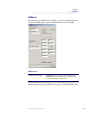
Modem . . . . . . . . . . . . . . . . . . . . . . . . . . . . . . . . . . . . . . . . . . . . . . . . . . . . . . . . . . . 285
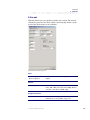
Dialog . . . . . . . . . . . . . . . . . . . . . . . . . . . . . . . . . . . . . . . . . . . . . . . . . . . . . . . . . . . . . 286
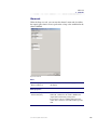
Language . . . . . . . . . . . . . . . . . . . . . . . . . . . . . . . . . . . . . . . . . . . . . . . . . . . . . . . . . 287
11
System communication . . . . . . . . . . . . . . . . . . . . . . . . . . . . . . . . . . . . . . . . . 288
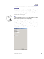
Send application . . . . . . . . . . . . . . . . . . . . . . . . . . . . . . . . . . . . . . . . . . . . . . . . . . 288
Sending data . . . . . . . . . . . . . . . . . . . . . . . . . . . . . . . . . . . . . . . . . . . . . . . . . 290
Get application . . . . . . . . . . . . . . . . . . . . . . . . . . . . . . . . . . . . . . . . . . . . . . . . . . . . 291
To get an application . . . . . . . . . . . . . . . . . . . . . . . . . . . . . . . . . . . . . . . . . 291
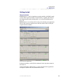
Error/event log . . . . . . . . . . . . . . . . . . . . . . . . . . . . . . . . . . . . . . . . . . . . . . . . . . . . 292
Getting the error/event log . . . . . . . . . . . . . . . . . . . . . . . . . . . . . . . . . . . . 292
Error/event log presented in IQANdevelop . . . . . . . . . . . . . . . . . . . . . 293
Clear the error/event log . . . . . . . . . . . . . . . . . . . . . . . . . . . . . . . . . . . . . . 294
Update vmAC . . . . . . . . . . . . . . . . . . . . . . . . . . . . . . . . . . . . . . . . . . . . . . . . . . . . . 295
Restart master . . . . . . . . . . . . . . . . . . . . . . . . . . . . . . . . . . . . . . . . . . . . . . . . . . . . . 297
Set clock . . . . . . . . . . . . . . . . . . . . . . . . . . . . . . . . . . . . . . . . . . . . . . . . . . . . . . . . . . 297
Display control . . . . . . . . . . . . . . . . . . . . . . . . . . . . . . . . . . . . . . . . . . . . . . . . . . . . 298
Modem . . . . . . . . . . . . . . . . . . . . . . . . . . . . . . . . . . . . . . . . . . . . . . . . . . . . . . . . . . . 299
Select modem . . . . . . . . . . . . . . . . . . . . . . . . . . . . . . . . . . . . . . . . . . . . . . . . 299
Connect via modem . . . . . . . . . . . . . . . . . . . . . . . . . . . . . . . . . . . . . . . . . . 299
Phone book . . . . . . . . . . . . . . . . . . . . . . . . . . . . . . . . . . . . . . . . . . . . . . . . . . 300
Export phone book . . . . . . . . . . . . . . . . . . . . . . . . . . . . . . . . . . . . . . . . . . . 300
User manual, IQAN Software G32
10
Contents
Import phone book . . . . . . . . . . . . . . . . . . . . . . . . . . . . . . . . . . . . . . . . . . . 300
No contact with the modem . . . . . . . . . . . . . . . . . . . . . . . . . . . . . . . . . . 300
Disconnect . . . . . . . . . . . . . . . . . . . . . . . . . . . . . . . . . . . . . . . . . . . . . . . . . . . 300
Chat . . . . . . . . . . . . . . . . . . . . . . . . . . . . . . . . . . . . . . . . . . . . . . . . . . . . . . . . . . 301
12
Access . . . . . . . . . . . . . . . . . . . . . . . . . . . . . . . . . . . . . . . . . . . . . . . . . . . . . . . . . 302
Application code . . . . . . . . . . . . . . . . . . . . . . . . . . . . . . . . . . . . . . . . . . . . . . . . . . 303
Add application code . . . . . . . . . . . . . . . . . . . . . . . . . . . . . . . . . . . . . . . . . 303
Deleting an application code . . . . . . . . . . . . . . . . . . . . . . . . . . . . . . . . . . 303
Opening a protected application . . . . . . . . . . . . . . . . . . . . . . . . . . . . . . 304
Licence number . . . . . . . . . . . . . . . . . . . . . . . . . . . . . . . . . . . . . . . . . . . . . . . . . . . 305
Access level . . . . . . . . . . . . . . . . . . . . . . . . . . . . . . . . . . . . . . . . . . . . . . . . . . . 305
Storing application codes . . . . . . . . . . . . . . . . . . . . . . . . . . . . . . . . . . . . . 306
Add and delete application codes . . . . . . . . . . . . . . . . . . . . . . . . . . . . . 307
Safe application codes . . . . . . . . . . . . . . . . . . . . . . . . . . . . . . . . . . . . . . . . 307
Run IQANdevelop with lower access level . . . . . . . . . . . . . . . . . . . . . . 309
13
Measuring and fault finding . . . . . . . . . . . . . . . . . . . . . . . . . . . . . . . . . . . . 311
Measuring in a block diagram . . . . . . . . . . . . . . . . . . . . . . . . . . . . . . . . . . . . . . 312
Measuring channels from the block diagram . . . . . . . . . . . . . . . . . . . 312
Measuring with the multimeter . . . . . . . . . . . . . . . . . . . . . . . . . . . . . . . . . . . . 314
Measuring channels in the multimeter window . . . . . . . . . . . . . . . . 314
Measuring objects . . . . . . . . . . . . . . . . . . . . . . . . . . . . . . . . . . . . . . . . . . . . . . . . . 316
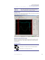
Measuring with the graph . . . . . . . . . . . . . . . . . . . . . . . . . . . . . . . . . . . . . . . . . 318
The measurement window . . . . . . . . . . . . . . . . . . . . . . . . . . . . . . . . . . . . 318
Channel information section . . . . . . . . . . . . . . . . . . . . . . . . . . . . . . . . . . 319
Starting and stopping measuring . . . . . . . . . . . . . . . . . . . . . . . . . . . . . . 324
Markers . . . . . . . . . . . . . . . . . . . . . . . . . . . . . . . . . . . . . . . . . . . . . . . . . . . . . . . 324
Zooming in/out . . . . . . . . . . . . . . . . . . . . . . . . . . . . . . . . . . . . . . . . . . . . . . . 326
Glitch detect . . . . . . . . . . . . . . . . . . . . . . . . . . . . . . . . . . . . . . . . . . . . . . . . . . 326
Print tags . . . . . . . . . . . . . . . . . . . . . . . . . . . . . . . . . . . . . . . . . . . . . . . . . . . . . 327
Adding a comment . . . . . . . . . . . . . . . . . . . . . . . . . . . . . . . . . . . . . . . . . . . 328
Print measured data . . . . . . . . . . . . . . . . . . . . . . . . . . . . . . . . . . . . . . . . . . 328
Copy measured data to another program . . . . . . . . . . . . . . . . . . . . . . 328
Save measured data . . . . . . . . . . . . . . . . . . . . . . . . . . . . . . . . . . . . . . . . . . 329
Settings of graph properties . . . . . . . . . . . . . . . . . . . . . . . . . . . . . . . . . . . 329
Channel properties . . . . . . . . . . . . . . . . . . . . . . . . . . . . . . . . . . . . . . . . . . . 330
14
IQANsimulate . . . . . . . . . . . . . . . . . . . . . . . . . . . . . . . . . . . . . . . . . . . . . . . . . . 331
Installation . . . . . . . . . . . . . . . . . . . . . . . . . . . . . . . . . . . . . . . . . . . . . . . . . . . . . . . . 332
Installing IQANsimulate . . . . . . . . . . . . . . . . . . . . . . . . . . . . . . . . . . . . . . . 332
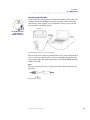
Connecting the CAN cable . . . . . . . . . . . . . . . . . . . . . . . . . . . . . . . . . . . . 333
Safety regulations . . . . . . . . . . . . . . . . . . . . . . . . . . . . . . . . . . . . . . . . . . . . . . . . . 334
Warning symbol . . . . . . . . . . . . . . . . . . . . . . . . . . . . . . . . . . . . . . . . . . . . . . 334
Testing the application for machine . . . . . . . . . . . . . . . . . . . . . . . . . . . 334
Getting started . . . . . . . . . . . . . . . . . . . . . . . . . . . . . . . . . . . . . . . . . . . . . . . . . . . . 335
The main window . . . . . . . . . . . . . . . . . . . . . . . . . . . . . . . . . . . . . . . . . . . . . 335
The menu bar . . . . . . . . . . . . . . . . . . . . . . . . . . . . . . . . . . . . . . . . . . . . . . . . . 336
The tool bar . . . . . . . . . . . . . . . . . . . . . . . . . . . . . . . . . . . . . . . . . . . . . . . . . . . . . . . 338
User manual, IQAN Software G32
11
Contents
The status bar . . . . . . . . . . . . . . . . . . . . . . . . . . . . . . . . . . . . . . . . . . . . . . . . . 338
The module panels . . . . . . . . . . . . . . . . . . . . . . . . . . . . . . . . . . . . . . . . . . . . . . . . 339
General . . . . . . . . . . . . . . . . . . . . . . . . . . . . . . . . . . . . . . . . . . . . . . . . . . . . . . . 339
Appearance . . . . . . . . . . . . . . . . . . . . . . . . . . . . . . . . . . . . . . . . . . . . . . . . . . 340
The channels . . . . . . . . . . . . . . . . . . . . . . . . . . . . . . . . . . . . . . . . . . . . . . . . . . . . . . 344
Inputs . . . . . . . . . . . . . . . . . . . . . . . . . . . . . . . . . . . . . . . . . . . . . . . . . . . . . . . . 344
Outputs . . . . . . . . . . . . . . . . . . . . . . . . . . . . . . . . . . . . . . . . . . . . . . . . . . . . . . 346
Using IQANsimulate . . . . . . . . . . . . . . . . . . . . . . . . . . . . . . . . . . . . . . . . . . . . . . . 347
Preparation . . . . . . . . . . . . . . . . . . . . . . . . . . . . . . . . . . . . . . . . . . . . . . . . . . . 347
Working procedure . . . . . . . . . . . . . . . . . . . . . . . . . . . . . . . . . . . . . . . . . . . 347
Functions . . . . . . . . . . . . . . . . . . . . . . . . . . . . . . . . . . . . . . . . . . . . . . . . . . . . . 347
Import and export settings . . . . . . . . . . . . . . . . . . . . . . . . . . . . . . . . . . . . 347
Automatic update . . . . . . . . . . . . . . . . . . . . . . . . . . . . . . . . . . . . . . . . . . . . 348
Updating IQANdevelop . . . . . . . . . . . . . . . . . . . . . . . . . . . . . . . . . . . . . . . 348
Simulating module errors . . . . . . . . . . . . . . . . . . . . . . . . . . . . . . . . . . . . . 348
Resetting the module errors . . . . . . . . . . . . . . . . . . . . . . . . . . . . . . . . . . . 348
Playback . . . . . . . . . . . . . . . . . . . . . . . . . . . . . . . . . . . . . . . . . . . . . . . . . . . . . . 348
Excel . . . . . . . . . . . . . . . . . . . . . . . . . . . . . . . . . . . . . . . . . . . . . . . . . . . . . . . . . 349
Simulating a TOC8 . . . . . . . . . . . . . . . . . . . . . . . . . . . . . . . . . . . . . . . . . . . . 350
Error and status codes . . . . . . . . . . . . . . . . . . . . . . . . . . . . . . . . . . . . . . . . . . . . . 351
Application codes . . . . . . . . . . . . . . . . . . . . . . . . . . . . . . . . . . . . . . . . . . . . . . . . . 354
Application code . . . . . . . . . . . . . . . . . . . . . . . . . . . . . . . . . . . . . . . . . . . . . . 354
Troubleshooting . . . . . . . . . . . . . . . . . . . . . . . . . . . . . . . . . . . . . . . . . . . . . . . . . . . 355
No contact with master . . . . . . . . . . . . . . . . . . . . . . . . . . . . . . . . . . . . . . . 355
Unstable contact with master . . . . . . . . . . . . . . . . . . . . . . . . . . . . . . . . . 355
Application does not work as expected . . . . . . . . . . . . . . . . . . . . . . . . 355
Excel does not work (as expected) . . . . . . . . . . . . . . . . . . . . . . . . . . . . . 356
File types IQANsimulate . . . . . . . . . . . . . . . . . . . . . . . . . . . . . . . . . . . . . . . . . . . . 357
The settings file [.iss] . . . . . . . . . . . . . . . . . . . . . . . . . . . . . . . . . . . . . . . . . . 357
The application and settings file [.ist] . . . . . . . . . . . . . . . . . . . . . . . . . . 357
Shortcuts . . . . . . . . . . . . . . . . . . . . . . . . . . . . . . . . . . . . . . . . . . . . . . . . . . . . . . . . . . 358
15
IQANdevelop for Palm OS . . . . . . . . . . . . . . . . . . . . . . . . . . . . . . . . . . . . . . . 359
Introduction . . . . . . . . . . . . . . . . . . . . . . . . . . . . . . . . . . . . . . . . . . . . . . . . . . . . . . . 359
Installation . . . . . . . . . . . . . . . . . . . . . . . . . . . . . . . . . . . . . . . . . . . . . . . . . . . . . . . . 360
Installing IQANdevelop for Palm OS . . . . . . . . . . . . . . . . . . . . . . . . . . . 360
Registration . . . . . . . . . . . . . . . . . . . . . . . . . . . . . . . . . . . . . . . . . . . . . . . . . . . . . . . 361
Accessing IQANdevelop conduit . . . . . . . . . . . . . . . . . . . . . . . . . . . . . . 361
Registration options . . . . . . . . . . . . . . . . . . . . . . . . . . . . . . . . . . . . . . . . . . 362
How to register... . . . . . . . . . . . . . . . . . . . . . . . . . . . . . . . . . . . . . . . . . . . . . . 364
...online . . . . . . . . . . . . . . . . . . . . . . . . . . . . . . . . . . . . . . . . . . . . . . . . . . . . . . . 364
...via registration file . . . . . . . . . . . . . . . . . . . . . . . . . . . . . . . . . . . . . . . . . . . 365
Connecting the PDA to the master . . . . . . . . . . . . . . . . . . . . . . . . . . . . . . . . . 366
HotSyncing . . . . . . . . . . . . . . . . . . . . . . . . . . . . . . . . . . . . . . . . . . . . . . . . . . . . . . . . 367
The synchronization process . . . . . . . . . . . . . . . . . . . . . . . . . . . . . . . . . . 368
The real McCoy . . . . . . . . . . . . . . . . . . . . . . . . . . . . . . . . . . . . . . . . . . . . . . . . . . . . 369
The main window . . . . . . . . . . . . . . . . . . . . . . . . . . . . . . . . . . . . . . . . . . . . . 369
User manual, IQAN Software G32
12
Contents
The application slots . . . . . . . . . . . . . . . . . . . . . . . . . . . . . . . . . . . . . . . . . . 370
The menu system . . . . . . . . . . . . . . . . . . . . . . . . . . . . . . . . . . . . . . . . . . . . . 370
The modes window . . . . . . . . . . . . . . . . . . . . . . . . . . . . . . . . . . . . . . . . . . . 372
The info window . . . . . . . . . . . . . . . . . . . . . . . . . . . . . . . . . . . . . . . . . . . . . . 373
The error log window . . . . . . . . . . . . . . . . . . . . . . . . . . . . . . . . . . . . . . . . . 373
The modules window . . . . . . . . . . . . . . . . . . . . . . . . . . . . . . . . . . . . . . . . . 374
The channels window . . . . . . . . . . . . . . . . . . . . . . . . . . . . . . . . . . . . . . . . . 374
Adjust . . . . . . . . . . . . . . . . . . . . . . . . . . . . . . . . . . . . . . . . . . . . . . . . . . . . . . . . 375
Measure . . . . . . . . . . . . . . . . . . . . . . . . . . . . . . . . . . . . . . . . . . . . . . . . . . . . . . 376
Graph . . . . . . . . . . . . . . . . . . . . . . . . . . . . . . . . . . . . . . . . . . . . . . . . . . . . . . . . 376
Application codes . . . . . . . . . . . . . . . . . . . . . . . . . . . . . . . . . . . . . . . . . . . . . . . . . 378
Managing application codes . . . . . . . . . . . . . . . . . . . . . . . . . . . . . . . . . . 378
Application code lifetime . . . . . . . . . . . . . . . . . . . . . . . . . . . . . . . . . . . . . 378
Getting a protected application . . . . . . . . . . . . . . . . . . . . . . . . . . . . . . . 379
Opening a protected application . . . . . . . . . . . . . . . . . . . . . . . . . . . . . . 379
Troubleshooting . . . . . . . . . . . . . . . . . . . . . . . . . . . . . . . . . . . . . . . . . . . . . . . . . . . 380
No contact with master . . . . . . . . . . . . . . . . . . . . . . . . . . . . . . . . . . . . . . . 380
Application does not work as expected . . . . . . . . . . . . . . . . . . . . . . . . 380
The application crashed and now I can’t start it again . . . . . . . . . . 380
Appendix A . . . . . . . . . . . . . . . . . . . . . . . . . . . . . . . . . . . . . . . . . . . . . . . . . . . . 381
Status-, warning- and error messages . . . . . . . . . . . . . . . . . . . . . . . . . . . . . . 381
Appendix B. . . . . . . . . . . . . . . . . . . . . . . . . . . . . . . . . . . . . . . . . . . . . . . . . . . . . 386
Priority order for the channels . . . . . . . . . . . . . . . . . . . . . . . . . . . . . . . . . . . . . . 386
Appendix C. . . . . . . . . . . . . . . . . . . . . . . . . . . . . . . . . . . . . . . . . . . . . . . . . . . . . 390
Choosing a modem . . . . . . . . . . . . . . . . . . . . . . . . . . . . . . . . . . . . . . . . . . . . . . . . 390
We recommend avoiding Winmodems and RPI modems . . . . . . . 390
We recommend using external modems . . . . . . . . . . . . . . . . . . . . . . . 390
We recommend using direct lines . . . . . . . . . . . . . . . . . . . . . . . . . . . . . 391
We recommend against "chasing the latest technology" . . . . . . . 391
We recommend getting a modem with the features you need . . 391
We recommend using well-known brands . . . . . . . . . . . . . . . . . . . . . 391
Buy from a store with a reasonable return policy . . . . . . . . . . . . . . . 391
If you need to buy many modems for a project . . . . . . . . . . . . . . . . . 391
If nothing else works . . . . . . . . . . . . . . . . . . . . . . . . . . . . . . . . . . . . . . . . . . 391
Appendix D . . . . . . . . . . . . . . . . . . . . . . . . . . . . . . . . . . . . . . . . . . . . . . . . . . . . 392
iSMS syntax . . . . . . . . . . . . . . . . . . . . . . . . . . . . . . . . . . . . . . . . . . . . . . . . . . . . . . . 392
Appendix E. . . . . . . . . . . . . . . . . . . . . . . . . . . . . . . . . . . . . . . . . . . . . . . . . . . . . 395
Recommendation of work method . . . . . . . . . . . . . . . . . . . . . . . . . . . . . . . . . 395
Vehicle steering for a forest machine . . . . . . . . . . . . . . . . . . . . . . . . . . 395
Part A . . . . . . . . . . . . . . . . . . . . . . . . . . . . . . . . . . . . . . . . . . . . . . . . . . . . . . . . . 395
Part B . . . . . . . . . . . . . . . . . . . . . . . . . . . . . . . . . . . . . . . . . . . . . . . . . . . . . . . . . 395
Appendix F. . . . . . . . . . . . . . . . . . . . . . . . . . . . . . . . . . . . . . . . . . . . . . . . . . . . . 397
Optimizing the application . . . . . . . . . . . . . . . . . . . . . . . . . . . . . . . . . . . . . . . . . 397
Group objects . . . . . . . . . . . . . . . . . . . . . . . . . . . . . . . . . . . . . . . . . . . . . . . . . . . . . 398
Lazy evaluation . . . . . . . . . . . . . . . . . . . . . . . . . . . . . . . . . . . . . . . . . . . . . . . . . . . . 399
Sort linear objects . . . . . . . . . . . . . . . . . . . . . . . . . . . . . . . . . . . . . . . . . . . . . 399
Object type priority . . . . . . . . . . . . . . . . . . . . . . . . . . . . . . . . . . . . . . . . . . . 400
User manual, IQAN Software G32
13
Contents
Sort conditional objects . . . . . . . . . . . . . . . . . . . . . . . . . . . . . . . . . . . . . . . 402
Object type priority . . . . . . . . . . . . . . . . . . . . . . . . . . . . . . . . . . . . . . . . . . . 402
Index . . . . . . . . . . . . . . . . . . . . . . . . . . . . . . . . . . . . . . . . . . . . . . . . . . . . . . . . . . 403
User manual, IQAN Software G32
14
1
1
Introduction
Introduction
IQANdevelop is a development tool for designing and developing application
programs for IQAN's module-based control systems.
IQANdevelop is a Windows©-based program with which you can create
applications for the simplest to the most complex mobile machine within forestry, excavation or material handling.
You develop your application in the PC to thereafter "download" the application to the IQAN system's master module. In IQANdevelop, you also find
functions for measuring and fault-finding which facilitates work during service.
The manual is intended to function as a reference book when working. In the
chapters, you find short explanations to all the menus and dialog boxes.
We show with examples how you create functions for the different channels
as well as how you use IQANdevelop's measuring system.
We have written a Getting started chapter as a practical introduction to
IQANdevelop and it is intended that you use the PC at the same time as you
read the chapter.
It is important to point out that the examples are not complete with regard to
safety and must not be used on a machine.
User manual, IQAN Software G32
15
Installing IQANdevelop
2
2
Installation
Installation
Installing IQANdevelop
Before you install IQANdevelop, please read the Safety regulations in
chapter 3.
• Insert the CD into your computer's CD-ROM unit. The installation program starts automatically. If not, open the CD-ROM unit in the Explorer
and double-click on Install.exe.
• Follow the instructions in the installation program. If there is something
you do not understand, click on the Next > button or press Enter to continue the installation.
• The installation file also contains IQANsimulate and IQANdevelop for
PalmOS. To install these softwares follow the instructions given by the
installation program.
You can always download the latest upgrade of IQANdevelop from our home
page, www.iqan.com.
User manual, IQAN Software G32
16
Warning symbol
3
3
Safety regulations
Safety regulations
This chapter contains regulations to improve safety when you use IQANdevelop. It is important that you read this chapter before you start creating
applications for machines.
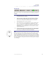
Warning symbol
Note that all warning symbols in the manual also refer to safety precautions.
This is what a
warning symbol
looks like!
Emergency stop
Without exception, every machine must have an emergency stop that can
break the power supply to the IQAN system or stop the diesel engine. It must
be easily accessible from the operator's position. IQANdevelop should not be
adjusted from locations where the user cannot reach the emergency stop, for
example outside the driver's cabin.
Testing the application for machine
A risk assessment should be carried out with regard to function and unpredictable occurrences. We refer to the standard for the Machine directives.
It is very important to test the program for the machine to check that nothing
unexpected occurs. IQANsimulate software is prepared for verification and
fault-finding of the application.
If the application is to be tested in machine, people and other objects that can
be injured or damaged must be out of range of the machine's working area.
User manual, IQAN Software G32
17
Sending data to the IQAN system
3
Safety regulations
Sending data to the IQAN system
When downloading data to the IQAN system, the machine's engine must be
switched off. No part of the machine, for example a crane, may be in
extended position. The machine must stand on a flat surface to prevent rolling. People or objects that can be damaged must be kept outside of the
machine's working area. Note that when the application is being downloaded
to the IQAN system, the system's output channels become inactive.
Downloading via modem
You need to be extra careful when sending data to the master via a modem.
Before the downloading can begin, the driver must acknowledge the downloading request on the master display.
Protecting the application
It is possible to protect the application in a machine with an application code.
In this way, you cannot get the application from the machine if you don't have
the code.
ALWAYS CONSIDER SAFETY WHEN DEVELOPING AND TESTING THE APPLICATION .
User manual, IQAN Software G32
18
4
4
Getting started
Getting started
This chapter is intended as a practical introduction to IQANdevelop which
means that you should use the PC at the same time as you read the chapter.
The intention of Getting started is to give you an overview of the contents and
functionality in IQANdevelop.
We have chosen to construct an application for a Reach Stacker where we will
create the following functions:
• Windshield wiper
• Automatic parking brake
• Forward and reverse lock
• Manoeuvring of boom and telescope
• End reduction function for boom and telescope.
• Limited lowering speed for the boom
• Overload protection
• Feedback wheel-steering
It is possible to work with the chapter at the speed you find appropriate as
well as using it as a reference when you have gathered more facts.
The application is
not complete and
cannot, therefore,
be used on a
machine!
NOTE
The examples are not complete in point of safety. The application must not be
used on a machine.
User manual, IQAN Software G32
19
Starting IQANdevelop
4
Getting started
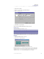
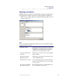
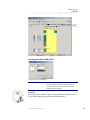
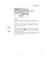
Starting IQANdevelop
To start the program, click on the IQANdevelop icon or the exe-file in the
Explorer.
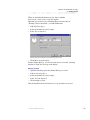
IQANdevelop’s main window is displayed.
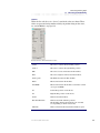
The main window in IQANdevelop.
In the main window, you find all the commands in the drop-down menus or as
buttons in the tool bar.
At the bottom of the window, there is a status bar which shows, for example,
your access level.
User manual, IQAN Software G32
20
Building an application in IQANdevelop
4
Getting started
Building an application in IQANdevelop
To create our Reach Stacker application, we will need the following modules:
• 1 IQAN-MDM (master module)
• 1 IQAN-XP (expansion module)
• 1 IQAN-Lx (lever)
The first thing we have to do to is to build up the module system in IQANdevelop. Every module is represented by a block diagram where we get access
to all channel types.
Add a master
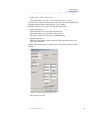
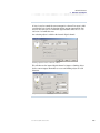
An IQAN system must always contain a master module. Therefore, we start
by adding this module.
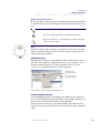
• Select: System > Add module. The following dialog box is opened.
Dialog box Add master module.
• Click OK to add the module IQAN-MDM.
Add IQAN-XP
The next module we need is an IQAN-XP (eXpansion Power module) to get
access to inputs and outputs.
• Select: System > Add module.
• Click in the drop-down list box Module type and select IQAN-XP. Check
that the CAN address is 0 and click OK.
Add IQAN-Lx
• Add IQAN-Lx, CAN address 0.
We have now added the three modules that we will need to create our Reach
Stacker application.
User manual, IQAN Software G32
21
Building an application in IQANdevelop
4
Getting started
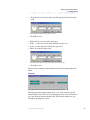
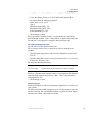
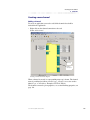
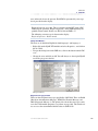
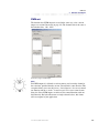
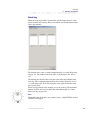
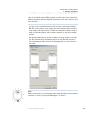
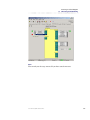
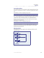
System overview
All added modules are represented in the system overview. To see the modules’ block diagrams click on respective module.
Tabs
Every module is represented in the system overview.
Alternating between block diagrams
IQANdevelop presents each block diagram in separate forms. You can easily
alternate between the block diagrams by clicking on tabs of the forms.
The forms' tabs.
User manual, IQAN Software G32
22
Naming and saving the application
4
Getting started
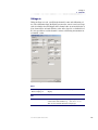
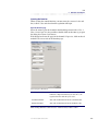
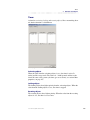
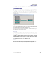
Naming and saving the application
In order to identify the application later you should name your application,
and save it with a filename that is explanatory.
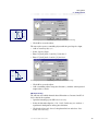
Application information
Application information includes description and version which helps you to
identify your application.
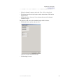
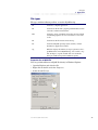
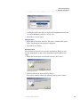
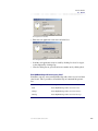
• Select: File > Info. The following dialog box is opened.
Application information dialog box.
• Enter Application description and Version. Click OK.
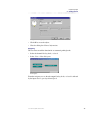
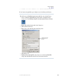
Save application
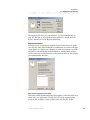
It is time to save your application.
• Select: File > Save as. The following dialog box is opened.
The dialog box to save a file.
User manual, IQAN Software G32
23
Naming and saving the application
4
Getting started
• Select the folder where you want to put your application and enter a file
name.
• Click Save.
Ensure that you save the application at regular intervals by using the Save button in the tool bar.
User manual, IQAN Software G32
24
Digital inputs and outputs
4
Getting started
Digital inputs and outputs
A typical function where we need to use digital inputs and outputs is the control for a windshield wiper. It is perhaps not the first function you construct on
a machine but it is a simple example to start with when introducing you to
IQANdevelop.
We have chosen to construct the functions in this chapter using our working
methodology with one exception, the safety aspect is omitted in order not to
make the introduction too extensive. For more information on the working
methodology, see section Recommendation of work method, on page 395.
What do we want to happen?
Pressing the button will give one stroke of the windshield wiper.
How will it work?
When the button is pressed, a pulse to the windshield wiper of at least 0.5 s is
generated.
What do we need to know?
If the button is pressed in.
To create the above-mentioned function, we need to use a digital output to
generate a pulse to the windshield wiper and a digital input to connect the button.
User manual, IQAN Software G32
25
Digital inputs and outputs
4
Getting started
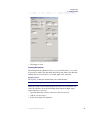
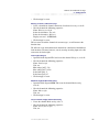
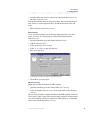
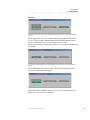
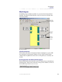
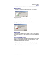
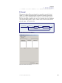
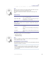
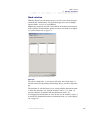
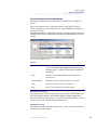
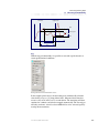
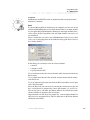
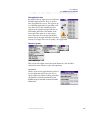
Creating the channels with their properties
Windshield wiper; digital out
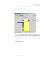
• Click on the XP-0 tab to open the block diagram for the module.
Channel
connection
Digital out,
index A1.
Name tag
Block diagram for XP-0.
• To create the digital output, right-click on the channel connection Digital
out, index A1 and select: Add channel. A name tag is created.
The channel has a pre-set name:
Channel type - Channel index: Module type - CAN address
NOTE
Every digital output has two channels. One primary and one secondary.
We will use the upper one, the primary.
(To Delete a channel, right-click on the channel’s connection and select
Delete channel. A dialog box to confirm the deletion is opened. Click Yes.)
User manual, IQAN Software G32
26
Digital inputs and outputs
4
Getting started
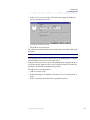
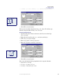
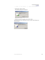
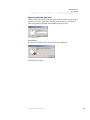
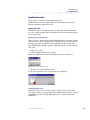
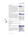
• Select the channel’s name tag and select: View > Show channel info.
• The dialog box Channel information consists of two forms. Click on the
Properties tab.
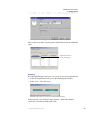
• Click in the Name, language 1 box and enter the name of the channel:
Windshield wiper.
The pulse that will activate the windshield wiper shall be 500 ms.
• Click in the Delay, off box and enter 500.
Properties for the digital output, Windshield wiper.
• Click on Apply to store.
User manual, IQAN Software G32
27
Digital inputs and outputs
4
Getting started
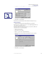
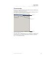
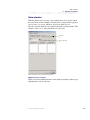
Windshield wiper, button; digital in
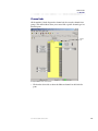
• Click on the tab for the lever unit Lx-0.
The lever unit is equipped with a number of digital inputs. We will use one of
them to connect the button for the windshield wiper.
Channel
connection
Digital in,
index A.
The block diagram for LX-0.
• To create the digital input, right-click on the channel connection Digital
in, index A and select: Add channel. A name tag for the channel is created.
• Select: View > Show channel info to open the dialog box Channel information.
• Click in the Name, language 1 box and enter the channel’s name: Windshield wiper, button.
• Click on Apply to store.
User manual, IQAN Software G32
28
Digital inputs and outputs
4
Getting started
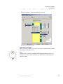
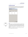
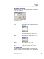
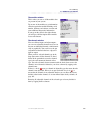
Creating the function
We will now create the function. When the digital input Windshield wiper,
button is activated, the Windshield wiper output will be activated. We will use
the channel Windshield wiper, button as the input signal to an activating
object for the output.
Windshield wiper
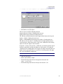
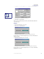
• Click on the Function tab in the dialog box Channel information.
• Right-click in Activating objects and select: Add object.
Function page for the digital output, Windshield wiper.
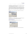
We will now enter an expression which will activate the digital output.
Windshield wiper, button = High
When the input signal Windshield wiper, button has the state high (1), the output Windshield wiper will be activated.
• As the above mentioned condition is a comparison, make sure that the
Comparison option is selected.
• Click in the drop-down list box for Input and select the channel Windshield wiper, button. A condition is suggested. Check that it is correct and
click OK.
User manual, IQAN Software G32
29
Digital inputs and outputs
4
Getting started
The dialog box for Activating objects.
We have now created the activating object and the function for the windshield
wiper.
Windshield wiper, button is
now an activating object.
An activating object for the function windshield wiper.
Navigating
By using IQANdevelop’s Navigator, you can get an overview of the function.
• Select the output Windshield wiper in the block diagram for XP-0.
• Select: View > Show Navigator.
Windshield wiper, button is connected to the output Windshield wiper.
In the navigator, every channel is represented by a block. The channels
affected by each other are linked with a line.
User manual, IQAN Software G32
30
Frequency input
4
Getting started
Frequency input
To show how to use a frequency input, we have chosen to make a function for
an automatic parking brake where the vehicle’s speed plays a central roll.
What do we want to happen?
Automatic activation of the parking brake when the machine stops and automatic release of the brake when you start driving.
How will it work?
When the speed is less than 1 km/h and the speed pedal is released, the parking brake is activated with a delay of 0.5 s.
As soon as the speed pedal is pressed, the parking brake is released.
For safety reasons, following will apply for the digital output for the brake:
High output signal -> Parking brake released.
Low output signal -> Parking brake on.
What do we need to know?
The vehicles´ speed.
If the speed pedal is pressed.
To solve the above problem, we need a digital output for the parking brake, a
digital input for the speed pedal’s safety switch as well as a frequency input
for the vehicle speed.
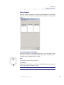
Creating the channels and their properties
We begin by creating the digital channels and their properties.
Parking brake, released; digital out
• Open the block diagram for XP-0.
• Create the digital output by right-clicking on the channel connection Digital out, index B1 and select: Add channel.
• Select: View > Show channel info.
• Enter the following name on the channel: Parking brake, released.
• The parking brake’s output signal shall be activated after 0.5 s. Click in the
box Delay off and enter 500 [ms].
• Click on Apply to store.
Switch, speed pedal; digital in
• Open the block diagram for Lx-0.
• Right-click on Digital in, index B and select: Add channel.
• Select: View > Show channel info.
User manual, IQAN Software G32
31
Frequency input
4
Getting started
• Enter the following name for the channel: Switch, speed pedal.
• Click on Apply to store.
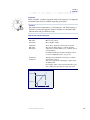
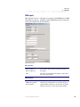
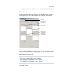
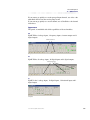
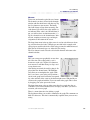
Speed; frequency in
We will now create the frequency input and define the channel’s properties.
• Right-click on Frequency in, index A in the block diagram for XP-0 and
select: Add channel.
• Select: View > Show channel info.
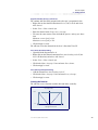
• Click in the Name, language 1 box and enter the channel name: Speed.
• Click in the upper Unit box and enter the unit km/h.
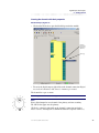
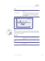
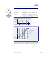
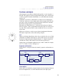
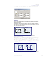
As the input is a frequency [Hz] signal we need to rescale the signal to the
unit [km/h] to be able to use it in our calculations. Scaling occurs as follows:
km/h
24
Speed km/h
The values are found
in a data sheet for
the frequency sensor
Frequency
338 Hz
Diagram for scaling the input signal.
Further information about the scaling and sensor type, see properties frequency in.
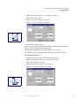
• Click in the Max [Hz] box and enter 338.
• Click in the Scaled max box and enter 24.
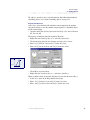
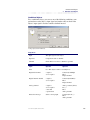
In this instance, we use an inductive passive sensor to measure the speed. To
indicate the signal from the sensor, we select Low trig level.
• Select the alternative Low trig level.
• Click on Apply.
User manual, IQAN Software G32
32
Frequency input
4
Getting started
Alternative buttons for
selection of trig level.
Properties for the frequency input Speed.
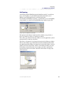
Creating the function
We will now create the function for the digital output, which is as follows:
When the speed is greater than1 km/h, the parking brake will be released
(off). The status for the output will be High.
When the speed is less than 1 km/h and the speed pedal is not pressed, the
parking brake will apply. The output’s status will be Low.
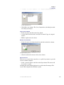
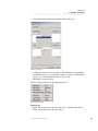
Parking brake, released
• Open the dialog box Channel information for the digital output, Parking
brake, released, XP-0.
• Click on the Function tab.
We begin with the speed pedal’s affect.
Switch, speed pedal = High => Parking brake, released
We will create an activating object to activate the output if the speed pedal is
pressed.
• Right-click in Activating objects and select: Add object.
• Select the Comparison alternative.
• Select: Switch, speed pedal as Input.
• IQANdevelop suggests a condition, check that it is correct according to
the above.
User manual, IQAN Software G32
33
Frequency input
4
Getting started
Dialog box for activating objects.
• Click OK to create the object.
We have now created the following function:
Speed pedal pressed down-> Parking brake released.
Speed pedal not pressed down-> Parking brake on.
We will now extend the function for the output with an object for the speed.
Speed > 1 km/h -> Parking brake released.
Speed < 1 km/h and Speed pedal not pressed down -> Parking brake on.
We will use a Locking object. A locking object has higher priority than an
activating object, which means that as soon as the conditions for the locking
object are true, the output’s value is locked.
In practice: as long as the speed is > 1 km/h, the system disregards the signal
from the switch in the speed pedal. However, if the speed is < 1 km/h, the
conditions for the locking object do not apply any longer and instead the conditions for the speed pedal that we created as an activating object will apply.
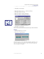
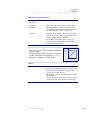
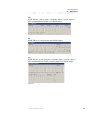
We create the following comparison:
Speed > 1.00 => Locks the output’s value
• Add a Locking object.
• Select: Speed [km/h] as Input.
• Click in the drop-down list box for operation characters and
select: > (greater than).
• Click in the drop-down list box for Operand and enter 1.00
User manual, IQAN Software G32
34
Frequency input
4
Getting started
Dialog box for Locking objects.
• Click OK to create the object.
• Close the dialog box Channel information.
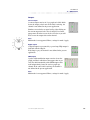
Navigating
We have now created the function for an automatic parking brake.
• Select the channel Parking brake, released.
• Select: View > Show Navigator.
The Navigator.
From the navigator, we see that the output Parking brake, released is affected
by the inputs Switch, speed pedal and Speed.
User manual, IQAN Software G32
35
Voltage input
4
Getting started
Voltage input
In this chapter, we will look at how to use analog voltage inputs. We will, for
example, connect analog sensors with a signal range of 0 - 5 Vdc.
To demonstrate how to use a voltage input, we have chosen to make a function for a forward/reverse lock to prevent change of direction when this is not
permitted. We need to measure the oil pressure to the parking brake with a
pressure sensor to get a voltage signal.
What do we want to happen?
Prevent switching between forward and reverse directions during operation
and also when the parking brake is applied.
How will it work?
Forward and reverse locks when speed exceeds 1 km/h.
Forward and reverse must not be active at the same time.
Forward or reverse must not be active if the parking brake pressure is low
(= parking brake applied).
What do we need to know?
The vehicle speed.
The status of the forward and reverse switch.
The parking brake pressure.
To solve the above problems, we need two digital outputs for the gearbox’s
forward and reverse, two digital inputs for the switch status, a frequency input
for the speed and an analog voltage input for the parking brake’s oil pressure.
Creating the channels and their properties
We begin by creating the digital channels.
Gearbox, forward; digital out
• Open the block diagram for XP-0.
• Right-click on the channel connection Digital out, index C and select:
Add channel.
• Select: View > Show channel info.
• Enter the following name: Gearbox, forward.
• Click on Apply to store.
Gearbox, reverse; digital out
Create Digital out, index D in the same way with the name: Gearbox, reverse.
User manual, IQAN Software G32
36
Voltage input
4
Getting started
Switch, forward; digital in
• Open the block diagram Lx-0.
• Right-click on the channel connection Digital in, index C and select:
Add channel.
• Select: View > Show channel info.
• Enter the following name: Switch, forward.
• Click on Apply to store.
Switch, reverse; digital in
Create Digital in, index D in the same way with the channel name: Switch,
reverse.
Speed; frequency in
In this function, we use the frequency input Speed that we created in the previous section. The frequency input is thereby ready.
Pressure, parking brake; voltage in
We will now create an analog input in the block diagram XP-0.
• Add the channel Voltage in, index A and open the Properties page.
• Click in the Name, language 1 box and enter: Pressure, parking brake.
• Enter the unit Bar in the upper Unit box.
As per specification, the pressure sensor’s signal varies within the voltage
range 500 mV - 4500 mV.
• Click in the Min [mV] box and enter 500.
• Click in the Max [mV] box and enter 4500.
To be able to use the pressure sensor’s signal, we need to rescale it to the unit
Bar. In the data sheet for the sensor, we see that the above voltage range corresponds to 0 - 35 bar.
• Click in the Scaled Min box and enter 0.00
• Click in the Scaled Max box and enter 35.00
User manual, IQAN Software G32
37
Voltage input
4
Getting started
Properties for the voltage input Pressure, parking brake.
• Click Apply to store.
Creating the function
The functions for the channels Gearbox, forward and Gearbox, reverse will,
in general, be similar. The only thing that will separate them is that the interlocking devices forward and reverse cannot apply at the same time.
Gearbox, forward
We begin by creating the main function, the switch function.
Switch, forward = high => Gearbox, forward will be activated
When the switch is in its forward position, Gearbox, forward shall be activated. To solve this, we need an activating object where the input signal
comes from Switch, forward.
• Open the dialog box Channel information, the Function tab.
• Add an activating object.
• Select the Comparison alternative.
User manual, IQAN Software G32
38
Voltage input
4
Getting started
• Select: Switch, forward as Input. Check that the suggested condition is
correct according to the above.
Activating object for Gearbox, forward.
• Click OK to create the object.
We will now extend the function with consideration to the affect of the parking brake.
(Switch, forward = high) AND (Pressure, parking brake > 30) => Activate Gearbox, forward
If the parking brake’s pressure exceeds 30 bar, the parking brake is released
and the output Gearbox, forward becomes active.
In practice, this means that as soon as the parking brake is applied, the pressure drops and the output Gearbox, forward becomes inactive to make sure
that there is no direction remaining in the gearbox.
We will create an activating object.
• Add an activating object.
• Select the Comparison alternative and select: Pressure, parking brake as
Input.
• Select < (less than) in the list box for operation characters.
User manual, IQAN Software G32
39
Voltage input
4
Getting started
• Enter 30.00 as Operand and click OK.
Activating object for Gearbox, forward.
We now have two activating objects for the output. We need to state that the
boolean operation AND will apply for the objects.
• Select the AND alternative for the activating objects.
Select the AND alternative.
Both activating objects have to be true to activate the output.
The last object for the function:
Speed > 1 km/h => Locks the output’s state
The speed must be less than 1 km/h to permit switching between forward and
reverse direction, that is the output Gearbox, forward is locked when the
speed is greater than 1 km/h.
As in previous section we choose to use the frequency input, Speed as input
signal to a locking object.
• Add a locking object.
• Select the Comparison alternative.
User manual, IQAN Software G32
40
Voltage input
4
Getting started
• Select Speed as Input.
• Select: > (greater than) as operation character.
• Enter 1.00 for Operand.
Locking object for Gearbox, forward.
• Click OK to create the object.
We have now created the function for Gearbox, forward.
Gearbox, reverse
Create the following for Gearbox, reverse.
(Switch, reverse = high) AND (Pressure, parking brake < 30) => Activate the output
Speed > 1.00 km/h => Locks the output’s state
After creating the function for Gearbox, reverse the whole function is done.
Navigating
• Select the channel Gearbox, forward.
• Select: View > Show Navigator.
The navigator shows the connection between the inputs and the output.
From the navigator, we see that the output Gearbox, forward is affected by
the inputs Switch, forward; Pressure, parking brake and Speed. Select the
channel Gearbox, reverse in the block diagram to see it’s inputs.
User manual, IQAN Software G32
41
Current outputs
4
Getting started
Current outputs
In this section, we will look at how to use the analog current outputs. A current output is used, for example, to control proportional valves. To look at
this, we have chosen to create a function to manoeuvre the boom and the telescope on the Reach Stacker machine.
What do we want to happen?
The boom and the telescope will be controlled, using a lever.
How will it work?
When the lever is in its centre position, both the boom and the telescope will
be stationary.
When the lever is in its maximum position, the boom and the telescope will
have maximum speed.
To get a more stabilized signal from the lever, there shall be a dead band of
10% around the central position of the lever.
What do we need to know?
The lever’s position in X direction.
The lever’s position in Y direction.
To solve the above problem, we need one analog current output for the boom
and one for the telescope. We need one channel for the lever’s position in X
direction and one channel for the lever’s position in Y direction.
The following directions are defined for the machine
Up
Down
Positive direction (+)
Negative direction (-)
Out
In
Positive direction (+)
Negative direction (-)
Right
Left
Positive direction (+)
Negative direction (-)
Creating the channels and their properties
We begin by creating the analog current outputs for the proportional valves.
Proportional valve, boom; current out
• Open the block diagram for XP-0.
• Right-click on the channel connection Current out, index A1 and select
Add channel.
As with the digital outputs, each channel connection has two outputs. We will
use the upper one.
User manual, IQAN Software G32
42
Current outputs
4
Getting started
• Select: View > Show channel info.
• Click in the Name, language 1 box and enter Prop. valve, boom.
We now need to enter the current range for the valve. We enter minimum and
maximum current, which correspond to 0 - 100 % output.
From the data sheet for the valve, we find the current values.
• Positive direction (+).
Click in the Min Current [mA] box and enter 200.
Click in the Max Current [mA] box and enter 500.
The above current values are pre-set in IQANdevelop.
• Negative direction (-)
Enter the values for the negative direction. They must be the same as for
the positive direction.
In other fields, there are pre-set values that we do not need to change for this
function.
Properties for the current output, Prop. valve, boom.
• Click on Apply to store.
User manual, IQAN Software G32
43
Current outputs
4
Getting started
Proportional valve, telescope; current out
We continue with the analog output for the telescope’s proportional valve.
• Right-click on the channel connection Current, Out, index B and select:
Add channel.
• Select: View > Show channel info.
• Enter the channel name: Prop. valve, telescope.
• We enter the same current values for both the positive and negative direction.
Minimum current [mA] = 200
Maximum current [mA] = 500
• Click on Apply to store.
We will now create the channels for the lever’s directions X and Y.
Lever, boom; directional analog
• Open the block diagram for Lx-0.
• Right-click on the channel connection Directional analog, index X (the
lever’s X direction) and select: Add channel.
• Select: View > Show channel info.
• Click in the Name, language 1 box and enter: Lever, boom.
• Click on Apply to store.
Lever, telescope; directional analog
• Add the channel Directional analog, index Y.
• Click in the Name, language 1 box and enter Lever, telescope.
• Click on Apply to store.
Creating the function
We will now create a function to make the boom move vertically.
The output’s value
100%
0%
-100
-10
10
100
%
Input signal Lever, boom
The lever signal’s affect on the output signal.
User manual, IQAN Software G32
44
Current outputs
4
Getting started
We will use controlling objects for this function. For further information on
controlling objects, see section Controlling objects, on page 224.
Proportional valve boom
As the Lever, boom channel will control the current output for the manoeuvring of the boom, we use this channel as input signal to a controlling object
for the current output.
• Open the dialog box Channel information for Prop. valve, boom. Click on
the Function tab.
We begin by creating the function in positive direction.
• Right-click in Controlling objects (+) and select: Add object.
• Click in the drop-down list box for Input and select: Lever, boom.
• Enter 10 [%] in the In 1 box and 0 [%] in the Out 1 box.
• Enter 100 [%] in the In 2 box and 100 [%] in the Out 2 box.
Out 2
Out 1
In 1
In 2
Controlling object(+) for the output Prop. valve, boom.
• Click OK to create the object.
• Right-click in Controlling objects (-) and select: Add object.
When we define values for negative direction, we enter the direction with (-).
• Select Lever, boom in the drop-down list box Input.
• Enter -10 [%] in the In 1 box and 0 [%] in the Out 1 box.
• Enter -100 [%] in the In 2 box and 100 [%] in the Out 2 box.
User manual, IQAN Software G32
45
Current outputs
4
Getting started
Out 2
Out 1
In 2
In 1
Controlling objects(-) for the output Prop. valve, boom.
• Click OK to create the object.
We have now created the function for Prop. valve, boom. We will now perform the same procedure for Prop. valve, telescope.
Proportional valve telescope
• Open the dialog box Channel information, the Function tab for Prop.
valve, telescope.
• Right-click in Controlling objects (+) and select: Add object.
• Select: Lever, telescope as Input.
• Enter 10 [%] for In 1 and 0 [%] for Out 1.
• Enter 100 [%] for In 2 and 100 [%] for Out 2.
Out 2
Out 1
In 1
In 2
Controlling object for the output Prop. valve, telescope (+).
• Click OK to create the object.
Now create the function for the proportional valve’s negative direction.
• Input= Lever, telescope
• In 1 [%] = -10, Out 1 [%] = 0.
• In 2 [%] = -100, Out 2 [%] = 100.
User manual, IQAN Software G32
46
Current outputs
4
Getting started
Out 2
Out 1
In 2
In 1
Controlling object for the output Prop. valve, telescope (-).
• Click OK to create the object.
We have now created functions to be able to control the boom and the telescope with a lever.
Navigating
• Select the channel Prop. valve, boom.
• Select: View > Show Navigator.
The navigator shows that Lever, boom is connected to the output Prop. valve, boom.
In the navigator, we see that the output Prop. valve, boom is affected by the
input Lever, boom.
• Click on the output Prop. valve, telescope.
The navigator shows that Lever, telescope is connected to the output Prop. valve, telescope.
In the navigator, we see that the output Prop. valve, telescope is affected by
the input Lever, telescope.
User manual, IQAN Software G32
47
Using more than one object for the current output
4
Getting started
Using more than one object for the current output
We will now describe another object type for the analog current outputs. We
have already looked at controlling objects. In this section, we will introduce
limiting objects.We have, therefore, chosen to extend the function for the
boom and telescope with a function for end position attenuation.
What do we want to happen?
Boom and telescope will brake before mechanical stop.
How will it work?
When the boom is 5° from its end position, the speed will be limited.
2° from the mechanical end position, the speed must not exceed 20 % of the
maximum speed.
When the telescope is 40 cm from its end position, the speed will be limited.
20 cm from the mechanical end position, the speed must not exceed 20 % of
the maximum speed.
Horizontal position for the boom = 0°, maximum angle for the boom = 60°.
Minimum extended telescope = 0 cm, maximum extended telescope 700 cm.
700 cm
What do we need to know?
The boom angle
The telescope’s position.
0 cm
60°
0°
To solve the above problems, we continue to build upon the previous application. We do, however, need an additional two analog voltage inputs for the
boom angle and the telescope’s position.
User manual, IQAN Software G32
48
Using more than one object for the current output
4
Getting started
Creating the channels and their properties
As we have already gone through how to create properties for the voltage
inputs, we will just give a few short instructions.
Angle, boom; voltage in
• Add the channel Voltage in, index B in the block diagram XP-0.
• Enter the following channel properties:
Name: Angle, boom
Unit: °, (degrees) (To write the ° symbol, press [Alt+248])
Minimum Voltage [mV] = 500
Maximum Voltage [mV] = 4500
Scaled min [°] = 0
Scaled max [°] = 60
• Click on Apply to store.
Position, telescope; voltage in
• Add the channel Voltage in, index C.
• Enter the following channel properties:
Name: Position, telescope
Unit: cm
Minimum Voltage [mV] = 500
Maximum Voltage [mV] = 4500
Scaled minimum [cm] = 0
Scaled maximum [cm] = 700
• Click on Apply to store.
Creating the function
Before we begin to create the functions, we will look at how IQANdevelop
handles controlling and limiting objects.
We will demonstrate this with a mathematical example. The function is applicable for the output Prop. valve, boom.
%
100
80
Controlling object 1
%
100
80
60
60
40
20
40
20
20 40 60 80 100 %
Input signal Lever, boom
Limiting object 1
52 54 56 58 60
%
Input signal Angle, boom
Controlling and limiting objects.
User manual, IQAN Software G32
49
Using more than one object for the current output
4
Getting started
The output’s value is determined by the following equation:
Output value = Minimum of [(Control 1 x Control 2 x Control 3..Control 8);
(Limiting 1, Limiting 2, Limiting 3..Limiting 8)]
From the diagram, we get:
Input signal Lever, boom = 50 % => Controlling object = 45 %.
Input signal Angle, boom = 58.5° => Limiting object = 30 %.
The objects’ output signals are compared and the least one gives the current
output’s value.
45% > 30% => The output signal is limited to 30%.
From the diagram, we get:
The lever’s input value = 50% => Controlling object = 45 %.
The boom’s angle = 52° => Limiting object = 100 %.
45% < 100% => The output signal will be 45%, i.e. it is not limited by the
limiting object.
Thus: If there had been several controlling objects, they would have been
multiplied to one product and then compared with the limiting objects.
For further information, see section Limiting objects, on page 226.
We will now create a function to get end reduction on the boom.
Proportional valve, boom
• Open the dialog box Channel information, Function tab.
• Right-click in Limiting objects (+) and select: Add object.
• Select: Angle, boom in the drop-down list box Input.
• Enter 55 [°] for In 1 and 100 [%] for Out 1.
• Enter 58 [°] for In 2 and 20 [%] for Out 2.
Out 1
Out 2
In 1
In 2
Limiting object for the output Prop. valve, boom (+).
• Click OK to create the object.
User manual, IQAN Software G32
50
Using more than one object for the current output
4
Getting started
• Right-click in Limiting objects (-) and select: Add object.
• Select Input: Angle, boom
• Enter 2 [°] for In 1 and 20 [%] for Out 1.
• Enter 5 [°] for In 2 and 100 [%] for Out 2.
Out 2
Out 1
In 1
In 2
Limiting object for the output Prop. valve, boom (-).
• Click OK to create the object.
We have now created the end position attenuation for the boom and will now
be able to create the function for the telescope.
The function is applicable for the output Prop. valve, telescope.
We will now create the function for the telescope’s movement in and out.
Proportional valve, telescope
• Open the dialog box Channel information, Function tab.
• Right-click in Limiting objects (+) and select: Add object.
• Select Input: Position, telescope.
• Enter 660 [cm] for In 1 and 100 [%] for Out 1.
• Enter 680 [cm] for In 2 and 20 [%] for Out 2.
Out 1
Out 2
In 1
In 2
Limiting object for the output Prop. valve, telescope (+).
User manual, IQAN Software G32
51
Using more than one object for the current output
4
Getting started
• Click OK to create the object.
• Right-click in Limiting objects (-) and select: Add object.
• Select Input: Position, telescope.
• Enter 20 [cm] for In 1 and 20 [%] for Out 1.
• Enter 40 [cm] for In 2 and 100 [%] for Out 2.
Out 1
Out 2
In 1
In 2
Controlling object for the output Prop. valve, telescope (-).
• Click OK to create the object.
We have now created a function for boom and telescope with end reduction.
Navigating
• Select the output Prop. valve, boom.
• Select: View > Show Navigator.
Two channels affect the output Prop. valve, boom.
Using the navigator, we can see that for the function the output Prop. valve,
boom is also affected by the input Angle, boom. Click on the output Prop.
valve, telescope to see it’s inputs.
User manual, IQAN Software G32
52
Mathematical analog channel
4
Getting started
Mathematical analog channel
It is possible to set up mathematical functions to create advanced applications. For this, we need mathematical channels. There are analog mathematical channels which give an “analog” value and digital mathematical channels
which give the state true or false.
In this section, we deal with analog mathematical channels. We are going to
create a function to limit the lowering speed of the boom if the load is too far
out (if the telescope is extended).
To look at the problem, we will divide the section up into two parts.
What do we want to happen?
Lowering of the boom will be stopped if the load is too far out.
How will it work?
When COG (Centre Of Gravity) is greater than 300 cm, the maximum output
current for the boom lowering will be limited.
When COG is 650 cm or more, the maximum current for the boom lowering
will be 20%.
What do we need to know?
COG (Centre Of Gravity), the distance between the centre of the load and the
front axle. Maximum permitted lowering speed as function of COG.
t
L1
Maximum current, lowering of boom [%]
a
100
20
300
650
COG
[cm]
COG
L2
To solve the problem we need to calculate the distance COG. For that, we
need a mathematical analog channel. To be able to create the application, we
have to divide the problem into two parts. In the first part, we assume that we
have COG as a result of a mathematical operation. In the second part, we will
show how to use the mathematical channel’s function to calculate COG.
User manual, IQAN Software G32
53
Mathematical analog channel
4
Getting started
Creating the channel and its properties
We need to create the COG channel in order to use it when we create the
function for the lowering of the boom.
• Open the block diagram MDM.
• Right-click on the channel connection Math analog, index A and select:
Add channel.
• Select: View > Show channel info.
• Give the channel the name: COG.
• Enter cm in the upper Unit box.
• Click on Apply to store.
Creating the function
We will now create the function to limit the lowering speed on the boom. We
need to create a limiting object for the output Prop. valve, boom.
Proportional valve, boom
• Open the function page for the channel Prop. valve, boom.
As this function concerns the lowering speed, we will only create a limiting
object for the boom’s negative direction.
• Right-click in Limiting objects (-) and select: Add object.
• Select: COG in the drop-down list box Input.
• Enter 300 [cm] for In 1 and 100 [%] for Out 1.
• Enter 650 [cm] for In 2 and 20 [%] for Out 2.
Out 1
Out 2
In 1
In 2
Limiting object for the output Prop. valve, boom (-).
• Click OK to create the object.
We now have to create the function for COG to make the application work.
User manual, IQAN Software G32
54
Mathematical analog channel
4
Getting started
Calculations with a mathematical analog channel
We will now demonstrate how to create a mathematical function using a
mathematical analog channel. The function gives an analog value.
What do we want to happen?
The distance between the centre of the load and the front axle will be calculated (= COG).
How will it work?
COG = cosα ∗ (L1+t)-L2
L1 = 860 cm
L2 = 580 cm
t
What do we need to know?
Angle, boom (= α)
Position, telescope (= t)
L1 and L2, see illustration
From the illustration, we get:
cosα = (COG+L2) / (L1+t)
=> cosα ∗ (L1+t) = COG+L2
=> COG = cosα * (L1+t)-L2
L1
a
COG
L2
Previously in our application, we have created the analog voltage inputs
Angle, boom and Position, telescope.
The distances L1 and L2 are set distances on the machine.
We need to create the function with a mathematical channel to calculate
COG.
The properties for the mathematical analog channel, COG, have already been
defined in the previous section.
Creating the function
• Open the block diagram MDM.
• Click on the channel COG and open the dialog box Channel information,
the Function tab.
On the page, it is possible to build mathematical expressions using 16 positions A-P. The expressions are divided into subexpressions. For further information, see section Mathematical analog, on page 246.
COG = cos(Angle, boom) * (860 + Position, telescope) - 580
• Right-click on a row and select: Add object.
User manual, IQAN Software G32
55
Mathematical analog channel
4
Getting started
A dialog box is opened to enter a mathematical expression.
• Click in the drop-down list box Operator and select: cos (cosine for the
angle).
• Check the Channel box and select Angle, boom in the drop-down list box
Operand B.
The mathematical expression for position A. ( = cos (Angle, boom)).
• Click OK to store.
• Right-click on a row and select: Add object.
• Select: + (addition) in the drop-down list box Operator.
• Enter 860 in the box Operand A.
• Select: Position, telescope for Operand B.
The mathematical expression for position B. (= 860 + Position, telescope).
• Click OK to store.
• Right-click on a row and select: Add object.
We will now multiply the expressions at position A and position B.
• Select: * (multiplication) in the drop-down list box Operator.
• Check the Channel box and select: A in the drop-down list box for Operand A.
User manual, IQAN Software G32
56
Mathematical analog channel
4
Getting started
• Check the Channel box and select: B in the drop-down list box for Operand B.
The mathematical expression for position C (= A* B).
• Click OK to store.
• Right-click on a row and select: Add object.
• Select: - (subtraction) in the drop-down list box Operator.
• Select: C in the drop-down list box for Operand A.
• Enter 580 in the box Operand B.
The mathematical expression for position D. (= C- 580, where C= A * B).
• Click OK to store.
We have now created the whole function to limit the lowering speed on the
boom.
Navigating
The navigator shows the connection of the channels to and from COG.
The navigator shows that the output Prop. valve, boom is affected by the
internal channel COG. We also see that the inputs Angle, boom and Position,
telescope affect the internal channel COG. The internal channels are grey.
The inputs and outputs are green.
User manual, IQAN Software G32
57
Channels for conditional messages
4
Getting started
Channels for conditional messages
The master unit, MDM, has a display for giving information to the machine’s
operator. In this section, we will show how to create text messages for the display. We have selected to extend the boom and telescope application with an
overload warning. To detect overload, we will use a mathematical digital
channel.
What do we want to happen?
There will be a warning before the overload occurs.
The movements Boom down and Telescope out will be blocked in the event of
an overload.
How will it work?
A warning message on the display will occur when the load weight reaches
90 % of the maximum weight.
When the load weight exceeds the maximum weight, the movements for
Boom down and Telescope out are blocked to prevent the machine from tipping.
A message will be shown on the display in the event of an overload.
What do we need to know?
The maximum permitted weight in relation to the position of the telescope
and the boom.
The load weight.
To look at the problem, we will divide the section up into two parts. First, we
will look at the blocking of the outputs at an overload indication and create
the corresponding text messages for the display. In the second part, we will
create the functions for the calculations of the different load situations.
For the warning messages, we need two conditional message channels.
We will use an analog sensor to measure the load weight. We connect this to
an analog current input. To calculate Maximum load and 90% of the maximum load, we use two mathematical analog channels and to indicate Overload, we use a mathematical digital channel.
User manual, IQAN Software G32
58
Channels for conditional messages
4
Getting started
Creating the channels and their properties
The messages we want to be shown on the display are Conditional messages.
For example, we want the operator to be warned with a message when 90% of
the maximum weight is exceeded and when Overload is indicated.
We will now create two channels for conditional messages.
Warning, overload 90%; conditional message
• Right-click on the channel connection, Conditional message, index A in
the block diagram MDM and select: Add channel.
• Select: View > Show channel info.
• Enter the channel name: Warning, overload 90% in the box Name, language 1.
• Select the alternative Text only, which, makes it possible to show three text
rows on the display.
• Remove the selection Show always.
• Click on the first row for Left display text, language 1 and enter: Warning!
Thereafter click on the second row and enter Close to overload.
Properties for the Conditional message, Warning overload 90%.
User manual, IQAN Software G32
59
Channels for conditional messages
4
Getting started
• Click on Apply to store.
Warning, overload; conditional message
• Create a channel for channel connection, Conditional message, index B.
• Give the channel the following properties:
Name: Warning, overload.
Select the alternative: Text only.
Select the alternative: Bold text.
Display text row 1: OVERLOAD.
• Click on Apply to store.
We have now created the channels for text messages, we will return to the
function later.
We will now create the mathematical channels for calculation of the different
load situations. We must, however, start by creating an analog input to be able
to measure the load weight.
Load weight; voltage in
• Open the block diagram XP-0 and create the channel Voltage in, index D.
• Give the channel the following properties:
Name: Load weight
Unit: ton
Min voltage [mV]: 500
Max voltage [mV]: 4500
Scaled min [ton]: 0
Scaled max [ton]: 45
• Click on Apply to store.
Maximum weight; mathematical analog
• Open the block diagram MDM and create the channel Math analog,
index B.
• Give the channel the following properties:
Name: Max weight
Unit: ton
• Click on Apply to store.
90% of maximum weight; mathematical analog
• Create the channel Math analog, index C.
• Give the channel the following properties:
Name: 90% of max weight
Unit: ton
User manual, IQAN Software G32
60
Channels for conditional messages
4
Getting started
• Click on Apply to store.
Overload; mathematical digital
A mathematical digital channel gives a result from a calculation as high, low;
true or false depending on whether the mathematical condition is fulfilled or
not.
Load weight > Maximum weight => Overload indication
If the input signal Load weight is greater than the input signal Maximum
weight, the condition is true and an overload is indicated. If the condition is
not fulfilled, the result is false.
We will now create the properties for a Mathematical, digital channel. The
procedure is the same as for the other channels but we will take it step by step
as it is a new channel type.
• Right-click on the channel connection Math, digital, index A and select:
Add channel.
• Select: View > Show channel info.
• Click in the Name, language 1 box and enter Overload.
• Click on Apply to store.
When we have created all channels, we can use them in functions for the current outputs.
Creating the function
The conditions for blocking during overload are only applicable to the movements Boom down and Telescope out. We will use limiting objects to block
the outputs. To attain a blocking result, we define 0 % output when overload
is indicated. This means that minimal current will be output and the boom and
the telescope will not move.
The overload condition is either true or false. (Either it is overload or not).
The limiting object’s value is as below:
%
100
The limiting object
False
True
Input signal overload
The input signal Overload.
User manual, IQAN Software G32
61
Channels for conditional messages
4
Getting started
For the boom, there will be a limiting object in the negative direction and for
the telescope, there will be a limiting object in the positive direction.
Proportional valve boom
• Open the dialog box Channel information, Function tab for the channel
Prop. valve, boom.
• Right-click in Limiting objects (-) and select: Add object.
• Select Overload in the drop-down list box Input.
• For In 1 = false, enter 100 [%] for Out 1
• For In 2 = true, enter 0 [%] for Out 2
Out 1
Out 2
In 1 In 2
Limiting object for the output Prop. valve, boom (-).
• Click OK to create the object.
We now carry out the same procedure to create the telescope’s function.
Proportional valve telescope
• Open the function page for the channel Prop. valve, telescope.
• Add a Limiting object (+).
• Select Input: Overload.
• For In 1 = false, enter 100 [%] for Out 1.
• For In 2 = true, enter 0 [%] for Out 2.
User manual, IQAN Software G32
62
Channels for conditional messages
4
Getting started
Out 1
Out 2
In 1
In 2
Limiting object for the Prop. valve, telescope (+).
• Click OK to create the object.
We will now create the functions for the channels Conditional message.
Warning, overload 90%
• Open the function page for the channel Warning overload 90%.
The function for a conditional message is as for a digital output with its activating, blocking and locking objects.
We will now define when the text for Warning overload 90%, will be activated. We create it as an activating object.
• Add an Activating object.
• Select Load weight as Input.
• Select: > (greater than) as operator character.
• Check the Channel box and select the channel 90% of max weight as
Operand.
Activating objects for Conditional message, Warning overload 90%.
• Click OK to create the object.
User manual, IQAN Software G32
63
Channels for conditional messages
4
Getting started
When an overload indication occurs, the above condition
Load weight > 90% of max weight also applies.
Therefore, we need to create a blocking object to remove the text
"Warning! Close to Overload", at overload indication.
• Add a Blocking object.
• Select the channel Overload as Input.
• Select True as Operand.
Blocking object for Conditional message, Warning, overload 90%.
• Click OK to create the object.
For the channel Warning, overload we only need to create one activating
function to "light" the message on the display.
Warning, overload
• Open the function page for the channel Warning overload.
• Add an Activating object.
• Select the channel Overload as Input.
• Select: True for Operand.
• Click on Apply to store.
Now the functions for the Conditional message channels are created.
User manual, IQAN Software G32
64
Channels for conditional messages
4
Getting started
Calculations with mathematical channels
What do we want to happen?
The maximum weight will be calculated as a function of COG.
How will it work?
t
Maximum weight
ton
45
L1
a
10
0
980
cm
COG
Maximum weight as a function of the telescope's position.
COG
L2
From the diagram, we get:
( Maxload ) – ( Maxload – Minload )
Maximum permitted weight = -------------------------------------------------------------------------------------------------- xCOG
COGmax – COGmin
From the diagram, we get:
MaxWeight
=
45 – 10
45 – ( ------------- )x COG
980 – 0
The maximum load weight for the machine is 45 tons.
The machine can, independent of COG, lift loads of less than 10 tons.
What do we need to know?
COG
As we have already calculated COG, we can use this when we calculate the
maximum weight.
User manual, IQAN Software G32
65
Channels for conditional messages
4
Getting started
Creating the function
Max weight
• Open the function page for the channel Max weight.
• Right-click on a row and select: Add object.
• Select: / (division) as Operator.
• Enter 35 as Operand A.
(The expression 45 - 10 = 35)
• Enter 980 as Operand B.
(The expression 980 - 0).
• Click OK to store.
• Right-click on a row and select: Add object.
• Select: * (multiplication) as Operator.
• Select: A as Operand A.
• Select: COG as Operand B.
• Click OK to store.
• Right-click on a row. Select: Add object.
• Enter the expression 45-B.
• Click OK to store.
90% of maximum weight
• Open the function page for the channel 90% of max weight.
• Select: Add object and enter the expression 0.90 * Max weight.
• Click OK to store.
Carrying out calculations with a mathematical digital channel
To indicate overload, we compare the current load weight with the maximum
load weight.
Load weight > Maximum weight => Overload indication
Overload
• Open the function page for the channel Overload.
• Right-click on a row and select: Add object.
• Select: > (greater than) as Operator.
• Select: Load weight as Operand A.
User manual, IQAN Software G32
66
Channels for conditional messages
4
Getting started
• Select: Max weight as Operand B.
The mathematical expression for position A.
• Click OK to store.
We have now created the overload function for the boom and the telescope
with accompanying warning messages on the display.
Navigating
In the navigator, there is not sufficient space for the complete function for
overload indication. We will look at the function in stages.
• Click on the channel Overload.
• Select: View > Show Navigator.
The navigator shows the connection between the internal channel Overload and respective output channels.
In the navigator, we see that the outputs Prop. valve, boom and Prop. valve,
telescope and the conditional message channels Warning, overload 90% and
Warning, overload are affected by the mathematical channel Overload.
The mathematical digital channel Overload is affected by the input Load
weight and the mathematical analog channel Max weight.
We will proceed to look at the channel Max weight.
• Click on the channel Max weight in the navigator. Thereafter click on the
channel COG.
User manual, IQAN Software G32
67
Channels for conditional messages
4
Getting started
The navigator shows the input signals to COG and also to the channels COG is connected.
In the mathematical analog channel Max weight, we use the value from the
mathematical analog channel COG. We have created the channel COG in a
previous section.
User manual, IQAN Software G32
68
PID regulator
4
Getting started
PID regulator
We have now reached the last section in this chapter. We will show you how
to use a PID regulator.
We have chosen to construct a feed-back wheel steering function for the
Reach Stacker machine. At high speed it shall not be possible to turn the
machine too sharply. We want to construct a speed-dependant control, where
the wheel angle is limited as the speed increases.
What do we want to happen?
It will be possible to manoeuvre the vehicle using a lever.
The wheel-steering will be speed dependant when you use the lever.
How will it work?
When the orbitrol is used, the lever manoeuvring will not work (i.e. when you
are using the steering wheel to manoeuvre the vehicle, the lever will not
work).
The wheel angle is limited with regard to the machine’s speed.
What do we need to know?
Is the orbitrol being used?
The lever actuation.
The machine’s speed.
The wheel angle.
To solve the above problems, we need an analog current output for the wheelsteering, a PID regulator to regulate the wheel-steering, an input for the lever,
two analog voltage inputs to measure the orbitrol pressure and the wheel
angle.
We will use the previously-used frequency input to measure the speed.
We will use an internal analog channel for the set value to the PID regulator
as we need two controlling objects, one for the speed and one for the lever
actuation, but we will deal with this later. To activate the regulation when the
steering wheel is not used, we will use an internal digital channel.
User manual, IQAN Software G32
69
PID regulator
4
Getting started
Creating the channels and their properties
We begin by creating the current output for the wheel-steering.
Wheel-steering; current out
• Open the block diagram XP-0 and add the channel Current Out, index C.
• Enter the channel name: Wheel-steering.
For wheel-steering, we define:
Right turn (clockwise)
positive direction
Left turn (counter-clockwise)
negative direction
• We use the following current range for both the positive and the negative
direction.
Minimum current [mA]: 200
Maximum current [mA]: 500
As they are pre-set in IQANdevelop, we do not need to change anything.
• Click on Apply to store.
If you use the steering wheel to manoeuvre the machine, the wheel-steering
occurs hydromechanically. The orbitrol distributes the oil in the servo-unit
depending on how you turn the wheel.
When you use the lever to manoeuvre the machine, the oil is distributed via
electromagnetic valves. By measuring the orbitrol pressure, we know if the
steering wheel is used or not.
Orbitrol pressure; voltage in
We create an analog current input where we connect a sensor.
• Create the channel, Voltage in, index E in the block diagram XP-0.
• Give the channel the following properties:
Name: Orbitrol pressure
Unit: Bar
From the data sheet, we find that:
Minimum [mV]: 500
Maximum [mV]: 4500
Scaled minimum [bar]: 0
Scaled maximum [bar]: 500
• Click on Apply to store.
Angle sensor, wheel; voltage in
The wheel-steering will be speed dependant, which means that the wheel
angle is determined by the lever stroke and the vehicle’s speed. We need to
measure the wheel angle to regulate the steering.
User manual, IQAN Software G32
70
PID regulator
4
Getting started
• Create the channel, Voltage in, index F in the block diagram XP-0.
• Give the channel the following properties:
Name: Angle sensor, wheel.
Unit: %
Minimum voltage [mV]: 500
Maximum voltage [mV]: 4500
Scaled minimum [%]: -100
Scaled maximum [%]: 100
• Click on Apply to store.
The angle sensor is installed so that 0 % corresponds to the wheel being
directed straight forward. -100 % corresponds to a complete wheel turn to the
left and 100 % corresponds to a complete wheel turn to the right.
Lever, wheel-steering; directional in
We will now create the channel for the lever.
We are going to use the lever’s z direction (z rocker) to manoeuvre the
machine.
• Open the block diagram Lx-0 and create the channel Directional analog,
index Z.
• Open the dialog box Channel information and enter Lever, wheel-steering
in the Name, language 1 box.
We define the following directions:
Upper z rocker
positive direction (the vehicle turns clockwise)
Lower z rocker
negative direction (the vehicle turns counter-clockwise)
The lever’s direction starts from the z rocker’s central position. We define the
total movement range for the rocker as -100% - 100% so that the rocker’s
central position is 0%.
• Click on Apply to store.
Speed; frequency in
For the speed signal, we will use the frequency input that we created in a previous section.
We will use the built-in PID regulator to create a feedback control system for
the wheel-steering. We want the PID regulator to regulate the wheel angle in
relation to the vehicle’s speed and lever stroke.
User manual, IQAN Software G32
71
PID regulator
4
Getting started
The set value: lever stroke and speed
+
Wheel-steering
The actual value = the wheel angle
Regulation of wheel angle.
The set value for the regulation depends on the vehicle’s speed and the lever’s
value.
The actual value for the regulation is the signal from the angle sensor on the
wheel axle.
PID, wheel-steering; PID
We will now create the channel for the PID regulator.
• Open the block diagram for MDM.
• Create the channel connection PID, index A.
• Open the dialog box Channel information and enter PID, wheel-steering
in the Name, language 1 box.
• Click on Apply to store.
Using internal analog channels
Command value, wheel-steering
As set value for the regulator, we will use the vehicle’s speed and the lever
actuation. For this, we will use an internal digital channel that we will use as
input signal to the PID channel.
• Open the block diagram for MDM and add the channel Internal analog,
index A.
• Open the dialog box Channel information and enter Command, wheelsteering in the Name, language 1 box.
• Click on Apply to store.
Creating the regulator's function
As the regulator’s set value, we will use the lever’s value and the vehicle’s
speed. Depending on the lever’s stroke and the vehicle’s speed, the wheel
angle is determined. We create these as controlling objects for the internal
analog channel.
User manual, IQAN Software G32
72
PID regulator
4
%
100
80
Controlling object 1
%
100
80
60
60
40
20
40
20
20 40 60 80 100 %
Input signal Lever, wheel-steering
Getting started
Controlling object 2
5
10 15 20 25
km/h
Input signal Angle, boom
The value from the internal analog channel has the unit [%].
Command, wheel-steering
• Open the function page for the channel Command, wheel-steering.
We begin by creating a controlling object with the lever’s input value.
• Add a Controlling object (+).
• Select: Lever, wheel-steering as Input.
• Enter 10 [%] for In 1 and 0 [%] for Out 1.
• Enter 100 [%] for In 2 and 100 [%] for Out 2.
Out 2
Out 1
In 1
In 2
Controlling object for the Internal analog channel (+)Command, wheel-steering.
• Click OK to create the object.
• Right-click in Controlling objects (-) and select: Add object.
• Select: Lever, wheel-steering as Input.
• Enter -10 [%] for In 1 and 0 [%] for Out 1.
• Enter -100 [%] for In 2 and 100 [%] for Out 2.
User manual, IQAN Software G32
73
PID regulator
4
Getting started
Out 2
Out 1
In 2
In 1
Controlling object for the Internal analog channel (-) Command, wheel-steering.
• Click OK to create the object.
We now need to create a controlling object with the speed signal as input.
• Add a Controlling object (+).
• Select: Speed as Input.
• Enter 10 [km/h] for In 1 and 100 [%] for Out 1.
• Enter 25 [km/h] for In 2 and 20 [%] for Out 2.
Out 1
Out 2
In 1
In 2
Controlling object (+) for the Internal analog channel Command, wheel-steering.
• Click OK to create the object.
• Add a controlling object in negative direction (-) with the same input and
output values as above.
PID wheel-steering
We will now state which channels that will function as Command and Feedback value for the regulator.
• Open the function page for PID wheel-steering.
• Select the alternative Bipolar (-100 - 100%). In this way, we can have a
regulation in both positive and negative direction.
• Click in the Command channel's drop-down list box and select: Command, wheel-steering.
User manual, IQAN Software G32
74
PID regulator
4
Getting started
• Click in the Feedback channel's drop-down list box and select: Feedback,
wheel-steering.
There are rules on how to dimension the PID parameters. We refer to the
Function chapter for more information. Enter the following values for the PID
parameters:
• P regulation = 100
• I regulation = 20
• D regulation = 0
Function page for PID wheel-steering.
We have now created the function for the PID regulation. The next step is to
define when the regulation will be activated, i.e. start. In this instance, we
want the regulation to begin when the orbitrol pressure is less than 40 bar,
then we know that the steering wheel is not used to manoeuvre the machine.
Orbitrol pressure; internal digital
To activate the PID regulator, we use an internal digital channel as we want a
time delay from when the orbitrol pressure drops below 40 bar until when the
lever can be used (the regulation starts).
• Add the channel Internal digital, index A in the block diagram MDM.
User manual, IQAN Software G32
75
PID regulator
4
Getting started
• Open the dialog box Channel information and enter Orbitrol inactive in
the Name, language 1 box.
To make the transition between using the steering wheel and using the lever
more stable, we want an operation delay of 1000 ms before the lever will
work.
• Enter 1000 [ms] in the Delay, on box.
Orbitrol inactive
As we want the regulation to start when the orbitrol pressure is less than
40 bar, we create an activating object for the internal digital channel
Orbitrol, inactive.
• Open the function page for the channel Orbitrol inactive.
• Add an Activating object.
• Select: Orbitrol pressure as Input.
• Select: < (less than) as operator character.
• Enter 40 as Operand.
Activating object for the Internal digital channel Orbitrol inactive.
• Click OK to create the object.
PID, wheel-steering
Define the activating channel for the PID regulator.
• Open the function page for the channel PID, wheel-steering.
• Select the channel Orbitrol, inactive in the drop-down list box Enabling
channel.
We have now created the complete function for the PID regulator, with Command value, Feedback value and activation of the regulation. All that remains
to do for everything to work is to connect the PID-regulator as a controlling
object to the current output Wheel-steering.
User manual, IQAN Software G32
76
PID regulator
4
Getting started
Wheel-steering
• Open the function page for the channel Wheel-steering.
• Add a Controlling object (+).
• Select PID wheel-steering as Input.
• Enter 0 [%] for In 1 and 0 [%] for Out 1.
• Enter 100 [%] for In 2 and 100 [%] for Out 2.
Out 2
Out 1
In 1
In 2
Controlling object (+) for the analog current output.
• Click OK to create the object.
• Right-click in Controlling objects (-) and select: Add object.
• Select channel PID, wheel-steering as Input.
• Enter 0 [%] for In 1 and 0 [%] for Out 1.
• Enter -100 [%] for In 2 and 100 [%] for Out 2.
Out 2
Out 1
In 2
In 1
Controlling object (-) for the analog current output.
• Click OK to create the object.
We have now created a feedback system for the wheel-steering.
User manual, IQAN Software G32
77
PID regulator
4
Getting started
Navigating
The navigator shows the connection to the PID regulator and the connection to the output Wheelsteering.
To the output Wheel-steering, we have connected the regulator PID, Wheelsteering. There are three channels which affect the PID regulator, Orbitrol
inactive, Command wheel-steering and Angle sensor, wheel.
To see which channel is connected to Orbitrol, inactive, click on the block for
the channel.
The connection between Orbitrol pressure and Orbitrol inactive and the connection to PID wheelsteering.
To see which inputs affect the set value, click on the channel Command,
wheel-steering in the block diagram.
Lever, wheel-steering and Speed affect the PID regulator's set value.
The internal analog channel Command, wheel-steering is affected by two
inputs; Lever, wheel-steering and Speed.
User manual, IQAN Software G32
78
Summary
4
Getting started
Summary
Hopefully, you now have learned something about what you can do in
IQANdevelop and with IQAN control systems.
As we have only briefly described the program in this chapter, we hope that
you will continue using the manual as a reference when you construct your
applications.
Verify the application
A very important part that we have not dealt with in this chapter is safety in
the application.
Always construct your application considering safety in every function.
Always check your application with a simulation tool to verify your functions.
Trouble-shooting
With IQANdevelop’s measuring functions, you can easily trouble-shoot your
application, for further information, see section Measuring and fault finding,
on page 311.
User manual, IQAN Software G32
79
5
5
Menu overview
Menu overview
This chapter deals with the following:
• the menu bar
• the tool bar
• the status bar
This section of the manual is intended as a reference to get information
quickly on different commands and the tool bar’s’ function buttons.
In the menu bar, you find drop-down menus with different commands. There
is everything from the usual commands Open, Save, Cut and Paste to those
which are more program-specific such as Add, Remove module.
The main window in IQANdevelop.
Some commands are needed more often than others. Therefore, we have created a tool bar with a number of function buttons. On every button, there is a
figure to symbolize the button’s function.
The status bar contains information which facilitates things for you during the
programming. For example, there is a description of which application is
loaded, the current user level as well as the status of the connection to the
IQAN system.
User manual, IQAN Software G32
80
The main window
5
Menu overview
The main window
You create your application from the main window. In the main window, there
is a menu bar, a tool bar and a status bar.
The commands are found in drop-down menus and the commands you need
most often are found on the buttons in the tool bar.
Menu bar
Tool bar
Status bar
Main window in IQANdevelop.
Depending on where in IQANdevelop you are, certain menus, commands and
function buttons are not available. These buttons and menus are shown in
grey, see screen illustration above.
User manual, IQAN Software G32
81
Drop-down menus
5
Menu overview
Drop-down menus
In the menu bar, the following menu headings are found: File, Edit, System,
View, Measure and Help. The drop-down menus are opened by clicking on
respective menu heading. You can also reach the menus by pressing
Alt+respective underlined letter key. E.g. Alt+F for the File menu, Alt+M for
the Measure menu.
File
Under the File menu, there are the usual file functions, such as New, Open,
Save and Print. There are also specific functions for IQANdevelop, such as
settings for communication, languages preferences for the display’s text messages as well as the manager for application codes.
New
Ctrl+N
Creates a new application.
Open...
Ctrl+O
Opens an existing application.
Save
Ctrl+S
Saves application.
Save as...
Saves the application with desired filename.
Info...
Shows general information on the application.
Application
code...
Protects the application with a code to keep unauthorized from making changes.
Print...
Ctrl+P
Prints channels, measured graphs and block diagrams.
Properties...
Here, you enter properties for communication, dialog and language for the application in IQANdevelop.
Predefined...
Here, you enter the data for the sensors you want
to use as predefined.
Application
code manager...
Lets you add and delete application codes to your
application code file.
Create safe
code...
Lets you create a safe application code that cannot
be read by anyone so you can safely send it via
email.
Exit
Exits the program. A dialog window is displayed if
you have not saved the application or the latest
changes.
User manual, IQAN Software G32
82
Drop-down menus
5
Menu overview
Edit
Under the Edit menu, there are the usual editing functions.
Undo
Ctrl+Z
Undo the latest command.
Cut
Ctrl+X
Cut channels.
Copy
Ctrl+C
Copy channels.
Paste
Ctrl+V
Paste channels.
Delete
Del
Delete channels.
Move channel to
Moves a channel to another module.
Copy properties
Factory defaults to adjustables.
Adjustables to factory defaults.
There are two alternatives when copying
properties, either are the factory default
properties copied to the adjustable or vice
versa.
Note that all channels with adjustable properties will be affected.
System
In the system menu, there are functions for adding and removing modules
from the application as well as functions to send or get an application from
the master module.
Add module
Shift+Ins
Adds a module to the application. The program
checks that the maximum number of modules
is not exceeded.
Remove module
Shift+Del
Deletes a module from the application.
To delete a module, all defined channels on
that module must first be deleted.
A warning message is displayed.
Module properties...
Shift+
Enter
To change a module´s properties. You need to
open the module´s block diagram before you
can select the command in the system menu.
Check application...
F9
Checks if the application contains any errors or
warnings.
Send application...
F2
Sends the application to the IQAN master.
Get application
F3
Gets the application from the IQAN master.
User manual, IQAN Software G32
83
Drop-down menus
5
Get error/event
log...
Ctrl+F3
Menu overview
Gets the error/event log together with the application from the IQAN master.
Update vmAC...
Updates the operating system in an IQAN
module.
Chat...
You can send text messages from IQANdevelop to communicate with an IQAN user.
Display control...
You can control and view the IQAN-MDM display via this dialog box.
Restart master
Restarts the IQAN master module without
breaking the power.
Clear error/event
log
Clearing the error and event log in the master.
Set clock
Set date and time in the IQAN master. The
clock on the PC is used as a reference.
If you want to enter another time, you must do
this from the IQAN display.
Connect via
modem...
By connecting a modem to an IQAN master, it
is possible to do remote communication. You
can send or get an application, chat and measure channels.
Disconnect
Disconnects the modem connection that was
used for remote communication.
View
Under this menu, there are functions to show the properties for a channel, the
navigator and the multimeter.
Show channel info
Ctrl+1
Shows properties and functions for a channel.
Click a channel and select Show channel info,
or double-click on the channel’s name.
Show navigator
Ctrl+2
The navigator is a tool to get an overview of the
connection between input and output channels.
Click a channel and select Show navigator.
Show multimeter
Ctrl+3
With the function Show multimeter, you get a
view of all channels you measure on.
You can measure on several channels located
on different modules at the same time.
User manual, IQAN Software G32
84
Drop-down menus
5
Next window
Previous window
F11
F12
Menu overview
If you have several windows/dialog boxes open
at the same time, you can alter between them
by selecting next window or previous window.
Measure
In the measure menu, you find functions to measure the different channels in
the modules. There are two types of measures; the multi-meter or you can
have the measure presented in the form of a graph. (To activate the graph window, click on the Graph tab in the upper left corner of the main window). For
further information, see section Measuring and fault finding, on page 311.
Start measure/
Stop measure
F4
Start/stop the measuring procedure.
Start automatically
When you activate a channel for measurement
in the block diagram, i.e. click on its measure
flag, the measure starts automatically without
you having to select Start measure.
Reset selected
The block diagrams are reset so no measure
flags are activated for measure.
Clear log
Ctrl+L
If you have used the graph during
measuring, you must clear the measure log
before you can select to measure on other
channels.
Zoom out
Ctrl+M
Restores window after you have zoomed in.
(i.e. zoom out to normal measure window).
Graph properties...
You can setup your measure window with
regard to colors and if you want a grid to be
shown or not.
Channel properties...
You can change scaling of the Y axis for one
channel and change the color of its curve.
Comment...
You can create comments for your measurements.
Create/Remove print
tags
Tags to identify the curves during print-out.
Open settings...
Opens measurement settings.
Save settings...
Saves measurement settings.
User manual, IQAN Software G32
85
Drop-down menus
5
Menu overview
Help
Under the Help menu, there are functions to get help in different ways.
Contents
F1
About...
User manual, IQAN Software G32
View the user manual. Requires Adobe Acrobat Reader.
Information box about IQANdevelop.
86
The tool bars
5
Menu overview
The tool bars
Certain functions need to be more accessible as you need to use them more
often. These functions are found as buttons in the tool bar. If you position the
mouse over a button, a short explanation about the button is shown.
By clicking on the desired button, its function is activated.
The main window tool bar
Function buttons in the tool bar.
File functions
The buttons for the file functions contain the usual Open, Save and Print
functions but there is also an information button to obtain information about
the application.
Open an existing application.
Save application.
Print
Show general information about the application.
System functions
The system functions handles sending and getting applications.
Send all data to IQAN master.
Get all data from IQAN master.
User manual, IQAN Software G32
87
The tool bars
5
Menu overview
Show functions
With the buttons below, you get information on the current channel, you can
activate the multimeter to measure the different channels as well as obtain an
overview of the application with the navigator.
Show channel information. Show properties and functions for the
channel. Mark the name for the channel and click on the button Show
channel info.
Show navigator. The navigator gives an overview of included channels
for one function.
Show multimeter. Gives an overview of all the channels you are measuring on.
After having activated desired channels for measurement click on
Show multimeter to show a window with all channels at the same time.
In this way, you can measure on several channels located on different
modules at the same time.
Measure functions
With the buttons, you can start or stop a measure.
Start measure. The button is enabled when the measure can start.
Stop measure. The button is enabled when measurement is in progress.
Help functions
If you need help, you can use the button below.
Help for IQANdevelop.
The module tool bar
Each module has two buttons at the top left corner of the module page; Module properties and Remove module.
Shows the properties dialog box for a module.
Removes current module from the application. You have to delete all
channels from the module before it can be deleted.
User manual, IQAN Software G32
88
The tool bars
5
Menu overview
The status bar
The status bar
The status bar consists of six smaller fields where the following information
is shown.
1
In the first field from the left, there is a short description of the button or
the field that the mouse is pointing to.
2
The name you have given the application is shown in the second field.
The padlock indicates whether the application is protected by an application code or not. If the padlock is unlocked, there is no code entered.
3
The third field gives the access level of the user.
4
The fourth field indicates if the IQANsimulate program is running and if
there is a connection between IQANsimulate and IQANdevelop. If the
chain is broken there is no communication. Click here to synchronize with
IQANsimulate, i.e. force IQANsimulate to use the same file as you have
opened in IQANdevelop.
5, 6
The fifth and sixth fields give status for the connection to the master. During connection, the square lamp in the fifth field is green. The sixth field
shows messages regarding the communication with IQAN.
NOTE
If the connection between the IQAN system and your PC is broken, click on
the green status lamp to try to reconnect. If this does not work, the supply
voltage to the IQAN master module may be too low or there may be a cabling
failure. Check the connection between the PC and the IQAN system and that
the correct COM-port is being used. Check that no other program is using the
same COM-port.
User manual, IQAN Software G32
89
Application information
6
6
Application
Application
An IQANdevelop file is called an application. The application contains all
information needed by the master module to control the machine. An application consists of application information, modules, channels and objects.
Application information
Select: File > Info to open the dialog box for application information.
Application information.
Application description
Description of the application, normally the machine
type or name. Max 19 characters.
Version
Version of the application. Helps you to do version
control of your applications.
Comment
Comment on the application, for example, how it
functions, etc. Max 255 characters.
Language 1 and 2,
Default
Select which languages this application uses. The
Allow "Change" level to
see channel functions
Check this to allow users at the "Change" level to see
the function tab in the channel information dialog box.
User manual, IQAN Software G32
default language is the one used the first time you
send an application to a master module.
90
Application information
6
Application
Date of change
The date when the latest change of the application was
carried out. Cannot be changed.
Changed by
Licence/id and name of the last person who made
changes in the application. Cannot be changed.
Click OK to store the information. Cancel closes the dialog box without storing above changes.
Language preferences
When developing an application in IQANdevelop, it is possible to give texts,
channel names and units in two languages.
The menu system in an IQAN master module can also be shown in two languages. The languages are the same as the ones selected in the application.
Languages supported by IQAN
English
Italian
German
Swedish
French
Finnish
Spanish
Norwegian
Portuguese
Danish
User manual, IQAN Software G32
91
File types
6
Application
File types
File types with the following suffixes are used in IQANdevelop:
.idt
Contains a complete application.
.idl
Contains an .idt-file and a graph log with information such
as header, comment and start time.
.idm
Contains a group of channels selected for measure. Graph
and channel properties are also stored such as colors and
scales.
.ide
Contains an .idt-file and an error/event log.
.ido
Contains an IQAN operating system, vmAC (= virtual
machine for Application Control).
.reg
Windows registry file. When you export a phone book or a
predefined sensor from IQANdevelop, it is saved in a .regfile. To import a .reg-file, double-click on it in the file
manager. It will be imported to Windows registry.
Properties for an IQAN file
You can get information on an IQAN file directly in Windows Explorer.
• Open the Explorer and select the file.
• Right-click on the file and select Properties.
• Select the tab File info.
Properties for an idt-file.
User manual, IQAN Software G32
92
Print
6
Application
Print
You can print the properties for channels or block diagrams plus the graph in
color or black/white.
• Select File > Print.
Dialog box for print.
Print
Printer name
The name of the printer selected. By clicking on Select,
the Print Setup dialog box is shown where you can select
different printers and settings.
Channels
Check this box for printing the channels’ properties and
functions.
Block diagram
Check this box for printing all block diagrams.
Graph
If you have a graph log, you can print it either in black/
white or color.
User manual, IQAN Software G32
93
Warnings and statistics
6
Application
Warnings and statistics
IQANdevelop keeps statistics of used channels and objects and checks that
the application is complete and correct regarding channels and functions.
• Select System > Check application to open the dialog box Warnings and
statistics or press F9.
The dialog box for warnings and statistics.
Errors
Errors are fatal for the application, and have to be corrected before sending
the application to the master.
Shared pin conflict
Channels that share the same physical connection.
IQAN-XP2, for example, uses the same physical
connections for several channel types. It is only
possible to use one channel type at a time.
Too many channels. Max
allowed is...
This messages is shown if you reach the maximum
limit of channels.
Too many current and
PWM outputs. Max...
This message is shown if you have used too many
current and PWM outputs.
Transmission rate conflict
J1939 channels that have the same J1939 id must
have the same transmission rate. See section SAE
J1939, page 188.
Too many J1939 input/output ids. Max allowed is...
Max allowed J1939 ids for one IQAN-XT2 is 10.
See section SAE J1939, page 188.
User manual, IQAN Software G32
94
Warnings and statistics
6
Application
System cycle time not
within limits for IQAN-XP
The IQAN-XP module can´t handle a system cycle
time shorter than 50 ms (valid range is 50 - 75 ms).
See section Other properties, page 107.
Engine speed channel missing
Feedback channel for E-Gas out is not selected.
E-Gas channel missing
Channel type Engine load is defined, but no E-Gas
out.
SMS input, multiple match
Two or more SMS inputs have the same Incoming
message specified. The master module cannot
determine which channel to match with an incoming message, see section SMS input, page 166.
Warnings
Warnings indicates problems in the application. The application will probably
work but maybe not as expected. It is possible to send the application with all
the warnings to the IQAN system.
Unused channel
Defined channels that are not used in any function.
Unit mismatch
Channels don’t have the correct unit. For example
command and feedback channels for a PID regulator should have the unit [%].
Incomplete function
The function for a current or digital output has no
controlling or activating objects. Missing parameters in functions such as activating, command or
feedback channel.
Missing names and units
Name and unit in one or both languages are missing.
Duplicate name
Two or more channels have the same name.
Priority
If a channel with lower priority is used in a function
for a channel with a higher priority. See section Priority order for the channels, page 386.
Delay time not divisible
by system cycle time
The delay time will be rounded towards zero to the
nearest number divisible by the system cycle time.
Example: System cycle time is 50 ms. If delay time
is 175 ms it will be rounded to 150 ms.
Transmit rate not divisible by system cycle time
Same as above, but for J1939 channels.
Statistics
In the Statistics field, the number of channels and objects are shown.
User manual, IQAN Software G32
95
7
7
Modules
Modules
This chapter deals with the following:
• IQAN modules
• system overview
• block diagram
• module properties
The IQAN system is based on adding necessary modules and thus designing
your own control system.
IQANdevelop contains a system overview of the modules and their name and
address in the application. This provides a quick overview of how you have
designed your IQAN system.
In IQANdevelop, every module is presented as a block diagram where the
different channels are represented. With the block diagram as a base, you can
create functions and properties for each channel. The channels used in an
application are provided with a name tag. In respective block diagram, you
can also connect internal measure functions to every channel, see section
Measuring and fault finding, on page 311.
All modules have properties like name and CAN-address but also specific
properties like dither frequency for IQAN-XP2.
User manual, IQAN Software G32
96
IQAN modules
7
Modules
IQAN modules
The IQAN system is built on a flexible module thinking. The system consists
of a master unit with built-in display and a number of expansion units and
lever units. Communication takes place via the system’s CAN-bus. More
information on the different modules is found on separate product sheets.
Master modules
The master module is a central unit in the system. All communication is
routed through the master. It also contains all non-module specific channels
such as PID regulators, counters and math channels. All mathematical calculations take place in the master. There can only be one master in an IQAN
system.
Module
Inputs
Outputs
-
alarm
voltage
digital (on/off)
frequency
alarm
current
digital (on/off)
PWM
voltage
digital (on/off)
current
PWM
Others
-
IQAN-MDM
SAE J1939
IQAN-TOC8
-
IQAN-TOC2
Expansion modules
The expansion modules are equipped differently with regard to inputs and
outputs. Which modules you should select depends completely on the functionality you want. There can be several modules of each type in an IQAN
system, depending on the master module and the expansion module type.
Module
Inputs
Outputs
voltage
frequency
current
digital (on/off)
Others
-
IQAN-XP
User manual, IQAN Software G32
97
IQAN modules
7
Modules
voltage
digital (on/off)
digital (on/off)
-
voltage
frequency
current
digital (on/off)
PWM
-
voltage
frequency
current
digital (on/off)
PWM
E-gas
SAE J1939
voltage
digital (on/off)
-
IQAN-XS
IQAN-XP2
IQAN-XT2
-
IQAN-XR
Levers
The levers use the CAN bus for communication. There are different kinds of
levers, currently IQAN-LL and IQAN-LM. Both are called IQAN-Lx since
they use the same electronics.
Module
Inputs
Outputs
Others
voltage
digital (on/off)
digital (on/off)
directional analog (x, y, z)
IQAN-Lx
User manual, IQAN Software G32
98
System overview
7
Modules
System overview
On the first page, System overview, the system is presented as you have
designed it with all the included modules.
System overview
The modules in an application are presented as follows: the master module is
always positioned at the top of the page. The expansion modules and levers
follow below.
If there is not sufficient space on the screen for all of the modules, use the
scrolling arrows on the right side.
Module information
In the system overview, you get the following data on the modules:
• Serial number: the module’s serial number
• Hardware version: the module’s hardware version
• Software version: the module’s software version
• Status: different status messages (only displayed when measuring)
User manual, IQAN Software G32
99
Block diagram
7
Modules
Block diagram
In IQANdevelop, the different modules are presented in the form of block
diagrams. In respective block diagram, you get an overview of all the channels in the module.
Tabs with
the module
designation.
Name tag
for the
channel.
Click on
the box to
measure
channel.
Block diagram XP-A0.
Channel connections
The channel connections for the physical inputs and outputs are green while
the connections for the internal channels are grey. Each is marked with a
channel index in alphabetical order and 1 or 2 for primary or secondary connection.
Browsing between the different block diagrams
Every block diagram is presented in a page. To alternate between the different
block diagrams, click on one of the tabs at the top of the window, or click on
the module image in the System overview.
Tabs for activating the different block diagrams.
User manual, IQAN Software G32
100
Creating a block diagram
7
Modules
Creating a block diagram
Adding a module
To add a new module, select: Edit > Add module.
List box with modules
The CAN bus identity
CAN address, information
on the module’s address.
Adding a module to the application.
Module type
A list of modules that can be added to the application.
The first module to add to a new application has to be
a master module which is also the only module possible to select.
CAN bus
The existing CAN bus is identified with an A. Future
master modules with support for multiple CAN buses
will offer CAN bus B, C, etc.
CAN address
CAN address shows the module’s corresponding
address on the CAN bus. The CAN address is automatically incremented, but can be manually altered. It
can also be changed later on.
Limitation of number of modules
IQANdevelop checks that there are no more modules than the maximum
number allowed of each type in the application. When the alternative disappears in the list box, no more modules of that type can be added.
Removing a module
One condition for removing a module is that it contains no channels in the
block diagram. To delete channels, see section Deleting a channel, page 121.
• Open the block diagram for the module to be removed.
User manual, IQAN Software G32
101
Creating a block diagram
7
Modules
• Select: Edit > Remove module
The following dialog box is displayed.
Dialog box Remove module.
• Click Yes to remove the module or No to leave it there.
An information message is displayed if you try to delete a block diagram containing channels.
User manual, IQAN Software G32
102
Channel tabs
7
Modules
Channel tabs
All the module´s block diagram has channel tabs that sort the channels into
groups. This will facilitate when you want to find a specific channel type in a
block diagram.
Channel
tabs
The IQAN-MDM module´s channel tabs.
• Click on the desired tab to show the different channels in the block diagram.
User manual, IQAN Software G32
103
Module properties
7
Modules
Module properties
By right-clicking on a module in the system overview or in its block diagram
and selecting Properties, a dialog box opens where you can change the module’s properties, such as name and address.
Naming the module
The tab for naming the module.
Name, language 1
Name, language 2
The module name in two different languages.
Function buttons
To store the new properties, click OK. The Cancel button closes the dialog
box without applying the changes.
The module name is shown above the block diagram and on the tab for
respective module. If you do not name the module, the module’s original
name and address are shown instead.
User manual, IQAN Software G32
104
Module properties
7
Modules
Name of
the
module.
Named lever module.
Changing the module’s CAN address
The tab for changing the CAN address.
CAN address
The module’s CAN address. You can give the module a new address. If the new address is taken by
another module of the same type it will switch
address with that module.
ATTENTION
Be cautious when switching addresses between modules addressed with an
Id-tag in the cabling, these modules also switch functions.
User manual, IQAN Software G32
105
Module properties
7
Modules
Frequency
Changing the dither frequency for current outputs
XP: The dither frequency is fixed (92 Hz) and cannot be changed.
TOC8, TOC2, XP2: The dither frequency is common for all current outputs.
Adjust the frequency according to the specific load.
XT2: The current outputs can have individual dither frequencies.
The frequency tab for IQAN-XT2.
Dither frequency
Enter desired dither frequency for the current outputs. The frequency range is 25-150 Hz.
PWM frequency
Some modules are equipped with PWM outputs (pulse width modulation).
The PWM frequency is adjustable. For some modules there can be an alternative PWM frequency that can be selected by the module.
PWM frequency
Enter desired frequency for the PWM outputs. The
frequency range is 25-2000 Hz for most modules.
For further information about the PWM output, see section PWM out, on
page 176.
PIN codes
With the PIN codes you can prevent unauthorized people to use the properties
menu in the IQAN master and/or to use the SIM-card in other modems or
telephones. PIN codes are supported by all master modules.
User manual, IQAN Software G32
106
Module properties
7
Modules
The tab for the PIN codes.
Properties PIN code
This PIN code is used to prevent unauthorized people to use the Properties menu in the
IQAN master. Check the box and enter a
code.
GSM PIN code
This PIN code is for the modem´s SIM-card,
(only for GSM modems). In this way the
SIM-card can be prevented to be used by
unauthorized people.
Check the box and enter the PIN code in the
field below. You will find the code in the
SIM-card documentation.
Other properties
Other properties are system cycle time, error/event log handling and SMS
handling.
System cycle time
The cycle time for an IQAN system can be set to 20-100 ms. The default
value is 50 ms. If you need faster response times you can lower the value, or,
if you need more processing power you should raise the value.
NOTE
Please be cautious when using a short system cycle time. Pay attention to the
utilization. The utilization should not be over 75%. For further information
about utilization, see section Module diagnostic, on page 160.
Log handling
When a log goes full, the default behavior is to delete the oldest records to
create room for new errors/events. The 1000 latest records are always kept in
the log.
You can override the default behavior by checking the boxes Error/Event log
handling, stop when full. Now, when a log goes full, no more errors/events
User manual, IQAN Software G32
107
Module properties
7
Modules
will be logged. When the log is emptied, see section Clear the error/event log,
on page 294, logging will continue again.
The actual number of records in the error log and in the event log can be measured by using module diagnostics, see section Module diagnostic, on page
160.
iSMS commands
The master module can handle incoming iSMS commands from external systems. The standard iSMS command syntax is described in Appendix D on
page 392.
Auto answer
This feature only concerns master modules with a modem attached. Master
modules with a display shows caller id when it detects an incoming call. The
user can then choose to accept the call or not by pressing OK or Cancel. This
behavior can be overridden by checking the box Allow answer without user
confirmation. Please use this function carefully, the machine user will not be
notified when someone is connecting to the machine via modem.
Master modules without any display always answer incoming calls automatically.
The tab for other module properties.
System cycle time
The default value for an IQAN system is 50
ms. The time can be 20-100 ms.
Error log handling, stop when full
Check this box to force the master to stop
logging errors when the error log is full.
Event log handling, stop when
full
Check this box to force the master to stop
logging events when the event log is full.
Enable iSMS commands
Enables handling of incoming iSMS
commands from external systems.
User manual, IQAN Software G32
108
Module diagnostic
7
Allow answer without user
confirmation
Modules
Normally, when you connect to an IQAN
MDM via modem, the user most confirm the
connection by pressing the OK button on the
display. If you check this box, the MDM will
answer the call without even notifying the
user. The phone symbol in the MDM display
will go off hook though.
NOTE
If you have an IQAN-XP module in your system, the system cycle time must
be set to 50-75 ms.
J1939
For information about the J1939 module properties, see section SAE J1939
Diagnostic, page 189.
Module diagnostic
In earlier versions of IQANdevelop there was something called Module diagnostic. This has now been replaced by a new channel type, called Module
diagnostic. For more information, see section Module diagnostic, on page
160.
User manual, IQAN Software G32
109
8
8
Channels
Channels
This chapter deals with the following:
• channel types
• how to name the channels
• how to define the different channels’ properties
The definition 'channels' is a collective name for the inputs and outputs found
on the different IQAN modules. There are also channels internally in the system, to handle for example, text processing and mathematical calculations.
The channels are used to collect and/or send data. In this chapter, we will
present IQAN’s analog, digital and internal channels.
The master unit’s display can handle and present information in two different
languages. You decide which of the two languages you wish to use. In this
way the driver can get the information presented in one language while the
service engineer can request the information in another language if so
desired. There may also be drivers of different nationalities on the same
machine.
To facilitate for design and any troubleshooting of the application, be consistent when you name the different channels. We will give you some recommendations on how to name the different channels with regard to their
function, see section naming channels.
When you create an application, you begin by defining the different channels’
properties. It is also important that you have defined the direction of motion
for the machine’s different movements. In the chapter, you will find recommendations for the selection of direction.
For example, properties are the name of the channel, calibration of signals
such as voltage and current values, alarm limits and delay times. The properties are specific for each type of channel.
User manual, IQAN Software G32
110
8
Channels
List of all channel types
Name
Short
Input/Output/
Internal/J1939
Analog/Digital
value
Alarm output
ALRM
Output
Digital
Conditional message
CMSG
Internal
Digital
Current output
COUT
Output
Analog
Digital input
DIN
Input
Digital
Digital output
DOUT
Output
Digital
Directional analog
DAC
Internal
Analog
E-Gas output
EGAS
Output
Analog
E-Gas position input
EPOS
Input
Analog
Engine load
ELD
Internal
Analog
Event counter
ECNT
Internal
Analog
Event log
ELOG
Internal
Digital
Frequency input
FIN
Input
Analog
Function parameter
FP
Internal
Analog
Hour counter
HCNT
Internal
Analog
Integrating limiting
ILC
Internal
Analog
Interactive message
IMSG
Internal
Analog
Internal analog
IAC
Internal
Analog
Internal digital
IDC
Internal
Digital
J1939 Analog input
JAIN
J1939
Analog
J1939 Analog output
JAOUT
J1939
Analog
J1939 Diagnostic
JDGN
J1939
Analog
J1939 Digital input
JDIN
J1939
Digital
J1939 Digital output
JDOUT
J1939
Digital
J1939 E-Gas
JGAS
J1939
Analog
J1939 Lamp indicator
JLIC
J1939
Digital
User manual, IQAN Software G32
111
8
Channels
Name
Short
Input/Output/
Internal/J1939
Analog/Digital
value
Math analog
MAC
Internal
Analog
Math digital
MDC
Internal
Digital
Memorizing
MEM
Internal
Analog
Mode Selection
MSC
Internal
Analog
Module diagnostic
MDGN
Internal
Analog
PID-regulator
PID
Internal
Analog
Pulse width modulated output
PWM
Output
Analog
SMS input
SMSIN
Internal
Analog
SMS output
SMSOUT
Internal
Analog
State selection
SSC
Internal
Analog
Timer
TMR
Internal
Analog
Voltage input
VIN
Input
Analog
User manual, IQAN Software G32
112
Inputs
8
Channels
Inputs
A short presentation of the different physical input channels. For more information about the physical data for the inputs, see separate data sheet or
instruction books for the modules.
Voltage in
The input signal at these inputs comes primarily from analog sensors and
levers. The unscaled range is dependant on which module you use but is normally 0-5000mV, the scaled range is application dependent.
Digital in
Physical inputs with value low or high. They are mostly used for buttons,
position sensors and guards.
Frequency in
Typical functions are speed measure or revolution measure. The unscaled
range is 0-32000 Hz and the scaled range is application dependent.
E-gas Position
Use this channel if you want to measure or show the value of e.g the actuator
positions. The unscaled value is 0-5000 mV and the scaled value is 0-100%.
The E-gas out use this channel as the feedback value during regulation.
User manual, IQAN Software G32
113
Internal channels
8
Channels
Internal channels
Directional analog channel
These channels are found on IQAN’s lever modules. There is one channel for
each lever direction, X, Y and Z. The value of each channel corresponds to
-100% - 100%.
Internal analog channel
The internal analog channels are used primarily as input signals for the regulators but they can also be used for other purposes, e.g. when you create a
function for a current output. The channel´s value is -100%- 100%.
Internal digital channel
With an internal digital channel, you can e.g delay a digital input signal, or
group objects that you use together in several channels when you create functions. The channel´s state is either true or false.
EXAMPLE
A button has to be pressed down for a certain time before the function
starts.
Mathematical analog channel
Using these channels, you can carry out mathematical calculations e.g. sine,
cosine, plus, minus etc.
Mathematical digital channel
Using a mathematical digital channel, you can carry out relational and logical
operations on input signals from other channels. The channel´s value is either
true or false.
EXAMPLE
Performance of boolean operations
PID regulator
PID regulators are used to do closed loop control, e.g. a straight-lift function
for a crane. The channel´s value is -100%- 100%.
Integrating limiting channel
This channel will normally be used as a limiting object in an analog output,
e.g Current out or E-gas out. It is similar to a PID with only the integrating
part enabled. The channel’s range is 0 - 100%.
User manual, IQAN Software G32
114
Internal channels
8
Channels
Conditional message
On the display, you can show messages for different situations, e.g. the oil
pressure during operation or a warning message indicating overload. The
channel can display up to two messages at the same time.
Interactive message
The message is shown when a certain condition is fulfilled. The value for the
channel can be active or inactive, but also F1, F2, F3 or ESC, depending on
the state of the display´s function buttons, i.e. you can use the buttons on the
display module as digital inputs.
Event counter
With this channel type is it possible to count different events, e.g. how many
times a specific alarm condition has been fulfilled. You can increase, decrease
or reset the channel´s value. The range is 0-32000.
Memorizing channel
This channel type is used to memorize or accumulate the value of a defined
input signal. The range is 0-32000.
EXAMPLE
On a wheel loader you need to control the total weight of the load. Use a
memorizing channel to accumulate the weight of the load.
Event log channel
Use this channel type to log data for a channel at certain conditions. The data
is stored in the errors/events log in the master and can be shown in IQANdevelop.
Timer
A timer channel can be used for timekeeping, delays, etc. The time range for
a channel is 0-32000 s with a resolution of 50 ms. To lengthen this time, the
timer channels can be connected sequentially.
Hour counter
The hour counter channels are used for time keeping at low time resolution,
e.g. to measure a machine’s operation time before service. The time range is
0-32000 hours with a resolution of two minutes.
Mode selection channel
With this channel type you can automatically change "driver" mode when
certain conditions are met. The value of the channel is 1-4.
User manual, IQAN Software G32
115
Internal channels
8
Channels
State selection channel
This channel is used to control the states conditions in a "state machine"
There can be up to eight states for a channel.
Module diagnostic channel
This channel is used to measure module diagnostics, such as Supply voltage,
Temperature and Utilization.
Function parameters
Function parameters are used as adjustable constants in functions. You can
adjust the function parameter values via the IQAN display or via IQANdevelop.
Engine load
This channel can be used to carry out power control for a diesel engine.
SMS input
Use this channel to read values from incoming messages via SMS (Short
Message Service). Requires a SMS-capable GSM modem connected to the
master module.
SMS output
Use this channel to send messages via SMS (Short Message Service) to external systems/GSM phones. Requires a SMS-capable GSM modem connected
to the master module.
User manual, IQAN Software G32
116
Outputs
8
Channels
Outputs
A short presentation of the different physical output channels. For more information about the physical data for the outputs, see separate data sheet or
instruction books for the modules.
Current out
The current outputs are analog and are used to e.g. control proportional
valves. The unscaled range is -32000 - 32000 mA. The scaled range is -100%
- 100%.
PWM out
PWM out, a pulse width modulation output to control pulsar valves. The
channel’s function is similar to the current outputs. The scaled range is -100%
- 100%.
Digital out
Physical outputs with value low or high. These are mostly used to activate
lamps, on/off valves or to pull relays.
On some modules the digital outputs have soft start and peak and hold functions to increase the valve’s life time and reduce the heat release in the valve.
Alarm out
A physical output with value low or high. It is used to alert in different situations. A warning lamp or siren may be connected at the output.
E-gas output
You will find the E-gas out on the IQAN-XT2 module. With this channel you
can create a regulation function to control e.g an actuator that is used to control the speed of a diesel engine. The channel´s scaled range is -100% - 100%.
Primary and secondary outputs
For most outputs, there are two channels, which enable you to control two
different functions in the machine using the same output.
One channel has primary status and the other channel has secondary status. If
the primary channel is active, the secondary channel cannot be activated at
the same time. If both of the channels are active at the same time, this is indicated as incorrect, the output is closed and an error message is displayed.
For more information on this, see section Primary and secondary channel, on
page 281.
User manual, IQAN Software G32
117
Outputs
8
Channels
NOTE
When using double functions, carefully check the affects of the functions on
one another. Safety precautions should be taken.
EXAMPLE
A backhoe loader with turnable chair. When you turn the chair, you must
invert the lever’s directions so that the manoeuvring of the vehicle’s steering will be correct. For this, you can use the current output’s primary and
secondary channels. If the chair is turned forward, the primary channel is
used and if the chair is turned backward, the secondary channel is used. A
switch in the chair indicates if the chair is turned forward or backward.
User manual, IQAN Software G32
118
SAE J1939
8
Channels
SAE J1939
There are some channel types used only during communication on the CANbus dedicated for the protocol SAE J1939. You find these channels on the
IQAN-XT2.
J1939 Analog input
This channel type represents values from different analog sensors implemented in the diesel engine. For example fuel and oil temperature. The properties for a channel are documented in the specification for SAE J1939 or are
supplied from the engine manufacturer.
J1939 Digital input
This channel type is used for on/off sensors in the diesel engine.
J1939 Throttle out
With this channel the IQAN system controls the speed of the diesel engine.
This channel represent the engine´s command value. The unscaled channel
range is 0-32000 rpm and the scaled range is 0-100%.
J1939 Lamp indicator
This channel is used to indicate an error situation. The manufacturer has specified which lamp will be activated and when according to a specific error. The
value for the channel is either true or false.
J1939 Diagnostics
The channels for diagnostic is aimed to show diagnostic messages on the display. For example if there is some error in diesel engine, information about it
will be sent to the IQAN system and a corresponding message will be presented on the display.
J1939 Analog output
Use this channel to send user-defined analog information on the CAN-bus,
e.g sending load weight to an external weight logging system.
J1939 Digital output
This is the same as J1939 Analog output, but digital information instead.
User manual, IQAN Software G32
119
Creating a new channel
8
Channels
Creating a new channel
Adding a channel
To create an application you need to add all the channels that shall be
included in the application.
• Right-click on the channel connection to be used.
Select: Add channel.
Name tag
Channel
connection
Creating a channel in the block diagram.
When a channel is created, its corresponding name tag is shown. The channel
name is predefined as follows: Channel type - Channel connection number:
Module type - CAN address. Example: COUT-A1:XP-A0.
The channel can now be given properties, see section Defining properties, on
page 124.
User manual, IQAN Software G32
120
Creating a new channel
8
Channels
Deleting a channel
• Right-click on the channel’s connection and select: Delete channel.
Dialog box to delete a channel.
• Click Yes to delete the channel or No to leave it there.
If a channel cannot be deleted
It is not possible to delete a channel that is used in an object.
The following message box is shown.
Message box that the channel cannot be deleted.
Moving a channel
It is possible to move channels between modules. In order to move a channel,
there must be a channel of the same channel type available on the destination
module.
Moving a channel within the same module
To move a channel within the same module, click on the channel to be moved
and drag it to another channel connection. If the new connection is already
occupied, these channels simply change places.
Moving a channel to another module
• Click on the channel to be moved and select: Edit > Move channel to or
right-click on the channel connection and select: Move channel to. The
modules with available channel connections are shown in a menu.
User manual, IQAN Software G32
121
Creating a new channel
8
Channels
• Select the channel’s destination module in the menu.
The modules
with available
channel
connections.
Moving a channel to another module.
Confirming move of channel
When you move a channel, you receive a message to confirm that the channel
will be moved. Click Yes or No.
NOTE
Consider that, if you move a channel with a predefined name (Channel type Channel connection number: Module type - CAN address), this name goes
with the channel.
User manual, IQAN Software G32
122
Naming channels
8
Channels
Naming channels
When you name channels, it is important to keep to the same standard
throughout the whole naming procedure. In reality, there is no right or wrong,
but it should be apparent from the name how the channel works.
....a little recommendation when selecting names
For digital inputs and outputs, a good naming standard is to name the input
and output after its active state.
EXAMPLE
A stop button should get the name Stop because the name applies when the
input for the stop button is activated.
For a parking brake, it is often appropriate that you activate the output
when you want it to release. Therefore the name of the output should be
Parking brake free.
For analog inputs and outputs, we normally give names after function, for
example, Oil pressure, Telescope, or Angle sensor, boom.
Direction of motion
Before you create an application for a machine, it is important to define the
directions of movement for all moving components such as levers, lifting,
crane turns, etc. Every movement has a positive direction and a negative
direction.
The most important thing is to be consistent with the direction selection when
you create an application, partly to facilitate things when documenting the
application and partly when troubleshooting or rebuilding.
You should be consistent when defining the direction.
....a small recommendation when selecting direction
Up
Down
Positive
Negative
Forward
Reverse
Positive
Negative
Right
Left
Positive
Negative
Right turn
Left turn
Positive
Negative
Out
In
Positive
Negative
User manual, IQAN Software G32
123
Defining properties
8
Channels
Defining properties
To use the inputs and outputs in an application, respective channel must be
configured. You do this by providing the channel with properties. To define
properties, open the dialog box for channel information. The dialog box looks
different depending on which type of channel you select. For example, properties are name, calibration of signals such as voltage and current values and
alarm limits.
Opening the dialog box channel information
• Select the channel’s name tag in the block diagram and select: View >
Show channel info.
Properties for voltage in.
It is also possible to double-click on the name tag to open the dialog box.
Function buttons
To store the new properties, click Apply. The Close button closes the dialog
box. Ensure that the properties have been stored before the dialog box is
closed.
User manual, IQAN Software G32
124
Voltage in
8
Channels
Voltage in
Under the Properties tab, you fill in the channel’s name and calibration values. The calibration adapts the IQAN system to the sensor’s zero-level. Properties also define what will happen if the channel takes on an invalid value or
if an alarm will be activated when the value of the signal is at a defined level.
It is also possible to read the channel’s current value during measurement or
to simulate a value.
Properties for voltage in.
Name
Name, language 1
Name, language 2
The channel’s name in the two languages shown on the
display.
Unit
Unit
The unit to be presented on the display together with the
scaled value of the channel, e.g. °, bar, liters, cm, etc.
You can also enter the unit in two languages.
User manual, IQAN Software G32
125
Voltage in
8
Channels
ATTENTION
When you define a channel’s properties for the two languages, it is important
to remember that the unit can differ depending on language.
EXAMPLE
You cannot enter a temperature in °C for language 1 and °F for language 2.
To do this, you need to adapt the channel’s function as calculations with
different units will give different results.
Calibrate and scale the input signal
Factory default
Min [mV]
Max [mV]
Voltage range for the input signal.
Min = lowest voltage.
Max = highest voltage.
Adjustable
Min [mV]
Max [mV]
To be able to adjust the value for Min [mV] and
Max [mV] from the display, you must check the
Adjustable box. This enables you to calibrate sensors
from the display.
For further information about the adjustable values,
see section Adjustable values, on page 213.
Scaled min
Scaled max
The input signal should be converted to a readable
value for the operator.
The value is presented on the display together with
the defined unit.
For example, at 0.8 V, the sensor will measure a pressure at 20 bar. See data sheet for respective sensor.
Scaled max
Scaled min
min
max
Scaling of the input signal.
User manual, IQAN Software G32
126
Voltage in
8
Channels
Set min, set max
Set min
Set max
To facilitate calibration of minimum voltage.
E.g. calibration of the input when you have connected an
analog position sensor for the telescope. Manoeuvre the
telescope to its minimum position and click on Set min.
The voltage from the sensor is measured and shown in
the display Min [mV].
The same procedure applies for the maximum voltage
when the telescope is in its maximal position.
For this, the channel must be activated for measure. Click
on the channel’s measure flag.
Measure and simulate
Consider personal
safety when simulating. Appropriate
safety precautions
should be taken.
Value [mV]
Shows the current value for the channel during measure.
This can be used when you calibrate the channel for each
individual sensor.
Simulated value
Simulate a value on the channel.
Check the box and enter a value in the field below. The
channel will use this value instead of the actual measured
value on the input.
Error value
Error value
If the channel’s value is outside the specified voltage
range, the illegal value is replaced by an error value.
Enter a proper scaled value for the channel.
Scaled value
Scaled max
Illegal value, low= Min/2
Illegal value, high= ((Vin max- Max)/2)+ Max
Scaled min
Min
Max
Vin max
Voltage range analog input
Detection of illegal value.
User manual, IQAN Software G32
127
Voltage in
8
Channels
For the IQAN system to be able to detect errors such as short circuit or power
failure, the signal’s voltage value must be within the min and max limits as
per the above diagram. If the signal level reaches the illegal range, a signal
error is indicated. When an illegal value is detected, the value at the input is
replaced with a fixed error value to avoid jeopardizing the machine’s function. This error value is entered when you declare the channel’s properties.
NOTE
An illegal value can cause a faulty function on the machine. Carefully consider critical and dangerous situations when the input signal’s value is incorrect and enter suitable replacement values.
Following messages are shown on the display.
• Input error low, if the value is under the specified value.
• Input error high, if the value is over the specified value.
Alarm
Alarm, low
Alarm, high
The alarm is activated when the input signal passes a
defined alarm limit.
Select type of alarm by checking the boxes.
In the field below, enter the level for the alarm limit. The
alarm limit considers the scaled value. You can define
both an upper and lower alarm limit for the channel.
Alarm, low = when the signal drops below the lower
alarm limit, the alarm is activated.
Alarm, high = when the signal exceeds the upper alarm
limit, the alarm is activated.
signal
upper alarm limit
lower alarm limit
t
Definition of alarm limits.
If an alarm is activated, an alarm text is lit on the display. For the text to disappear, you must acknowledge by pressing a button to confirm that you have
User manual, IQAN Software G32
128
Voltage in
8
Channels
been informed of the alarm text. The alarm text also disappears when the
alarm signal returns to normal, i.e. the alarm has disappeared.
The following messages can be shown on the display:
• Alarm low, if the value drops below the specified value, below the alarm
limit.
• Alarm high, if the value exceeds the specified value, above the alarm limit.
All the alarms are logged in the error log in the master for further information, see section Error/event log, on page 292.
Filtering the input signal
Filter
Use a filter to attain greater stability in the channel’s signal. The value is entered in [%].
A signal which varies quickly, sometimes needs to be dampened.
EXAMPLE
The signal from the level meter in a fuel tank. When you drive in rugged
terrain the fuel splashes around in the tank and the signal from the level
meter becomes unstable. It can be a good idea to allow the signal to pass
through a filter.
NOTE
It is important to point out that too strong a filter can affect the signal too
much. If the channel is used for closed-loop regulation, it can become slow
and self-induced oscillation can occur in the system.
Value
1
25%
50%
75%
90%
0
0.05
0.1
0.15
0.2
0.25
0.3
0.35
0.4
0.45
0.5
sec.
Step response for analog input signal.
User manual, IQAN Software G32
129
Voltage in
8
Channels
The filter is not linear.
Predefined sensors...
• Via the Select predefined sensor button, you have access to a list with a
number of named and calibrated input signals for different sensor types.
• Click in the list to see the whole list with calibrated signals. It is also possible to extend this list with your own input signals.
Predefined sensors list.
• Select a sensor and click OK. The Cancel button closes the dialog box
without registering any selected alternatives.
Creating predefined sensors
It is possible to add sensors in "the sensor list".
• Select: File > Predefined.
List with calibrated sensors.
Add a sensor
• Click on the Add button.
User manual, IQAN Software G32
130
Voltage in
8
Channels
Add a sensor.
Name and unit
Name
Name of the sensor.
Unit
The unit to be presented on the display together with
the scaled value of the channel. E.g. °, bar, liters, cm,
etc.
You can also enter the unit in two languages.
Calibrate and scale the input signal
Min [mV]
Max [mV]
Voltage range for the input signal.
Min = lowest voltage
Max = highest voltage
Scaled max
Scaled min
The input signal should be converted to a readable
value for the operator. The value is presented on the
display together with the defined unit.
For example, at 1.5 V, the sensor will measure a volume at 65 liters. See data sheet for respective sensor.
Click OK to save changes. The Cancel button closes the dialog box without
saving any changes.
Editing a sensor in the list
• Select the sensor and click on the Edit button.
The dialog box for the sensor is opened.
User manual, IQAN Software G32
131
Voltage in
8
Channels
List with calibrated sensors.
• Click OK to save changes. The Cancel button closes the dialog box without saving any changes.
Copy a sensor in the list
• Select the sensor and click on the Copy button.
• A copy of the selected sensor is created. It is named "Copy of <original
name>".
• Edit the copied sensor. See above.
Delete a sensor in the list
• Select the sensor to be deleted in the list and click on the Delete button.
Message for deleting a sensor.
• Click Yes to delete the sensor or No to leave it there.
Export sensor list
You can save a sensor in the sensor list as a .reg-file if you want to e.g use the
sensor on another computer.
• Select a sensor in the list and click on the Export button. The sensor will
be saved in a .reg file.
To import the sensor, double click on the .reg-file in the file manager. The
sensor will be imported into Windows registry.
User manual, IQAN Software G32
132
Digital in
8
Channels
Digital in
Under the Properties tab, you fill in the channel’s name. It is also possible to
simulate a value.
Properties for digital in.
Name
Name, language 1
Name, language 2
The channel’s name in the two languages shown on
the display.
Measure and simulate
Simulated value
Simulate a value on the channel.
Check the box and select a value in the field below.
The channel will use this value instead of the actual
measured value on the input.
Consider personal
safety when simulating. Appropriate
safety precautions
should be taken.
User manual, IQAN Software G32
133
Frequency in
8
Channels
Frequency in
Under the Properties tab, you can name the channel and enter the calibration
values for the signal. It is possible to define if the alarm will be activated
when the value of the channel reaches a level as well as filter the signal, read
the channel’s value or simulate a value.
Properties for frequency in.
Name and unit
Name, language 1
Name, language 2
The channel’s name in the two languages shown on
the display.
Unit
The unit to be presented on the display together with
the scaled value of the channel.
User manual, IQAN Software G32
134
Frequency in
8
Channels
Calibrate and scale the input signal
Factory default
Max [Hz]
Maximum frequency at the input.
Adjustable
Max [Hz]
If you wish to be able to adjust the value for Max
[Hz] from the display, check the Adjustable box.
For further information about the adjustable value,
see section Adjustable values, on page 213.
Scaled max
The input signal should be converted to a readable
value for the operator. The value is presented on the
display together with the defined unit.
For example, if the input signal is a speed, you
present the value in km/h instead of the frequency
value found on the channel.
EXAMPLE
To rescale frequency [Hz] to revolutions [rpm] for
a diesel engine.
Assume max diesel engine revolution = 3000 rpm
Assume the number of cogs/engine rev. = 135
Frequency = (3000/60)* 135 = 6750 Hz
Scaled
value
Max [Hz]
Set max
Set max
User manual, IQAN Software G32
Set the maximum value for the frequency input.
Let the sensor which is connected to the input generate the frequency which will correspond to the
scaled value. Click on Set max.
The frequency value is measured and entered in the
Max [Hz] box.
For this function, you must first activate the channel
for measure. Click on the channel’s measure flag.
135
Frequency in
8
Channels
Trig level frequency signal IQAN-XP
Low, trig level
High, trig level
(pre-set)
As the frequency signal has different amplitudes
depending on different types of sensors, you must
define on which level the IQAN system will detect the
signal to calculate the frequency.
For example, frequency sensor with high signal amplitude should use high, trig level(=2.5 V).
Passive inductive sensors with a low signal amplitude
should use low trig level (=0.25 V).
The IQAN system measures the time period between
two flanks which are positive to one another. The frequency is then calculated from this.
High trig level is pre-set.
Measure and simulate
Consider personal
safety when simulating. Appropriate
safety precautions
should be taken.
Value [Hz]
Shows the current value for the channel.
Can be used when calibrating the channel for a unique
sensor.
Simulated value
Simulate a value on the channel.
Check the box and enter a value in the field below. The
channel will use this value instead of the actual measured value on the input.
Alarm
Alarm, low
Alarm, high
If the alarm is to be activated when the input signal
passes a defined alarm limit.
Select type of alarm by checking the boxes. In the
field below, you enter the level for the alarm limit.
The alarm limit considers the scaled value.
Alarm, low = when the signal drops below the lower
alarm limit, the alarm is activated.
Alarm, high = when the signal exceeds the upper
alarm limit, the alarm is activated.
For further information, see section Alarm, on page 128.
User manual, IQAN Software G32
136
Frequency in
8
Channels
Filtering the input signal
Filter
Use a filter to attain greater stability in the channel’s
signal. The value is entered in [%].
An analog signal which varies quickly can require dampening, for example,
the revolutions signal from a diesel engine. The signal must pass through a
filter.
EXAMPLE
If you want to regulate the speed of manoeuvring of a crane turn as a function of how hard the diesel engine works, you would have a very unstable
regulation. In this case, dampen the revolution signal from the diesel
engine with a filter.
For further information, see section Filtering the input signal, on page 129.
User manual, IQAN Software G32
137
Directional analog
8
Channels
Directional analog
The only property for a directional analog channel is the name. The channel
has a default range of -100%- 100%.
Properties for directional analog channel
Name
Name, language 1
Name, language 2
User manual, IQAN Software G32
The channel’s name in the two languages shown on
the display.
138
Internal analog
8
Channels
Internal analog
Under the Properties tab, you can name the channel and enter the rise and fall
time for the signal.
In addition you can define a BWL (Band Width Limiting) window. This function will decrease the frequency bandwidth of the output signal whenever the
change of the output signal is smaller than BWL window. The bandwidth limit
will decrease linearly with smaller changes. When the change of the signal is
zero, the bandwidth will also be zero. When the signal change is larger than
the window, no bandwidth limitation will be used. This function is particularly good to use for signals that are "nervous" but where a normal filter
would decrease the overall dynamics of the signal, e.g joystick control for a
crane function.
Properties internal analog.
Name
Name, language 1
Name, language 2
User manual, IQAN Software G32
The channel’s name in the two languages.
139
Internal analog
8
Channels
Slope times
+/-
The values below are entered for positive and negative
direction respectively.
Start slope [ms]
Stop slope [ms]
Enter the time it should take for the value to rise from
min to max and the time it should take for the value to
fall from max to min.
Channel
Check the Channel box to select a channel as min and
max for start or stop slopes.
BWL window [%]
Enter size of window for bandwidth limiting.
EXAMPLE
By using a internal analog channel it is possible to calculate different
slopes for different situations.
User manual, IQAN Software G32
140
Internal digital
8
Channels
Internal digital
Under the Properties tab, you fill in the channel’s name. By using the Delay,
on/off property, it is possible to delay the on/off transition of the signal.
Properties for internal digital.
Name
Name, language 1
Name, language 2
The channel’s name in the two languages shown on
the display.
Delay on/off
Delay, on [ms]
User manual, IQAN Software G32
The time delay is given in [ms].
E.g. if you require a button to be pressed down for a
certain time before a function starts.
If the function is activated shorter time than the specified delay on time, the channel´s state will not be
affected.
141
Internal digital
8
Delay, off [ms]
Channels
The time delay is given in [ms].
E.g. if you want a function to continue a time after you
have released the button (the input signal has
returned).
If the function is blocked shorter time than the specified delay off time, the channel´s state will not be
affected.
For further information about the delay on/off properties, see section Digital
out, on page 178
Switch status for the output signal
Toggle
The channel’s state will alternate between true and
false for every activation of the channel. Every other
time the state is true, every other time false.
Function value
t
Channel value
t
Internal digital with toggle.
User manual, IQAN Software G32
142
Mathematical analog
8
Channels
Mathematical analog
Under the Properties tab, you can name the channel and enter the unit for the
channel value.
Properties for mathematical analog channel.
Name and unit
Name, language 1
Name, language 2
The channels’s name in the two languages.
Unit
The unit to be presented on the display together with
the value of the channel.
User manual, IQAN Software G32
143
Mathematical digital
8
Channels
Mathematical digital
Under the Properties tab, you enter the name of the mathematical digital
channel.
Properties for mathematical digital channel
Name
Name, language 1
Name, language 2
User manual, IQAN Software G32
The channel’s name in the two languages.
144
PID
8
Channels
PID
Under the Properties tab, you enter the channel’s name.
Properties for PID regulation.
Name
Name, language 1
Name, language 2
User manual, IQAN Software G32
The channel’s name in the two languages.
145
Integrating limiting
8
Channels
Integrating limiting
This channel is used for example to limit the power-pressure for diesel engine
in different situations. The only property for this channel is the name.
Properties for the Integrating limiting channel.
Name
Name, language 1
Name, language 2
User manual, IQAN Software G32
The channel’s name in the two languages.
146
Conditional message
8
Channels
Conditional message
With this channel type you can create messages that will be shown at certain
conditions. A conditional message channel can show up to two messages or
channel values at one time. There are also possibilities to always show a messages when the display is in operating mode.
Properties for the conditional message channel.
Name
Name, language 1
Name, language 2
User manual, IQAN Software G32
The channel’s name in the two languages.
147
Conditional message
8
Channels
Layout
Text only
There is room for three rows of text on the display.
Text and channel
There is room for one text row and one row showing
the value of a selected channel. If you choose to show
only one channel, the name of the channel is also
shown.
Channel
Select the channel to be shown with the text message.
(Check the Layout alternative Text and channel)
Bar graph
Bar graph, left
Bar graph, right
The channel´s value is presented as a bar graph on the
display.
Graph min
Graph max
Specify the limits for the bar graph.
Graph min< Graph max
Graph min
Graph max
Graph min
Graph max
Graph min> Graph max
Graph min= Graph max
Graph min
Graph min
Graph max
0
Graph max
Graph min = - x
Graph max= x
The bar graph will act different dependent on how the limits are specified.
Display text left and right
Display text, language 1
Display text, language 2
The text message which is displayed when a certain
condition has been fulfilled.
The message can be shown in two languages.
By checking the box Show always the message will
always be shown when the display is in operating
mode.
Dual channels
By checking this box two messages will be shown.
One to the left and one to the right.
User manual, IQAN Software G32
148
Conditional message
8
Channels
Text option
Bold text
The text will be written with bold font.
Show always
Show always
By checking the Show always box, you get an extra
menu page in the display’s operation mode, where
the specified messages will be shown. Browse with
the display buttons to manually select a page.
If you also create a function for the channel, the
menu page can be shown automatically when a certain condition is fulfilled.
Delay on/off
Delay, on [ms]
Delay, on is entered in [ms].
If the function is activated shorter time than the
specified delay on time, the channel´s state will not
be affected.
Delay, off [ms]
Delay, off is entered in [ms].
If the function is blocked shorter time than the specified delay off time, the channel´s state will not be
affected.
For further information about the Delay on/off, see section Digital out, on
page 178.
User manual, IQAN Software G32
149
Interactive message
8
Channels
Interactive message
This channel type is used to present messages that can be acknowledged with
the function buttons on the IQAN display. This will give you an opportunity
to create functions that depends on which button is pressed when the message
is shown. On the properties page you can enter the text message and the text
for the function buttons.
To create interactive messages on the display.
Name
Name, language 1
Name, language 2
The channel’s name in the two languages.
Layout
Text only
There is room for three rows of text on the display.
Text and channel
There is room for one text row and one row showing
the value of a selected channel. If you choose to show
only one channel, the name of the channel is also
shown.
User manual, IQAN Software G32
150
Interactive message
8
Bold text
Channels
The text will be written with bold font.
Display text
Display text, language 1
Display text, language 2.
The text message which is displayed when a certain
condition has been fulfilled. The message can be
shown in two languages.
Channel
Select the channel to be shown with the text message.
(Check the Layout alternative Text and channel).
Function button text
To be able to use a function button from the display you need to supply the
button with a text. If a button doesn’t have a text, the message can’t be
acknowledged by that button, i.e. the button is disabled.
NOTE
You must always take into consideration that the ESC-button can be pressed.
User manual, IQAN Software G32
151
Event counter
8
Channels
Event counter
This channel is used to count events. The range is 0-32000. The counter stops
when it reaches 0 or 32000.
Properties for the channel event counter.
Name
Name, language 1
Name, language 2
The channel’s name in the two languages shown on
the display.
Store the counter’s value
Store value
The channel value is stored in non-volatile memory.
In this way, the value is stored even if you break the
supply voltage to the system. Otherwise the value will
be reset to zero at startup. See also section Stored values, page 214.
Allow reset to zero
The channel value can be reset to zero from the display or via iSMS, see Appendix D, page 392.
User manual, IQAN Software G32
152
Memorizing
8
Channels
Memorizing
This channel type is used to memorize a channel´s value at certain conditions.
The memorized value can either be replaced or added up by a new one. If you
select to store the memorized value in the master´s memory it will remain
unaffected when you break the supply voltage.
Properties for the Memorizing channel type.
Name
Name, language 1
Name, language 2
The channel’s name in the two languages shown on
the display.
Channel to memorize
Memorize channel
Select the channel that you want to memorize.
Action
Replace
The memorized value is replaced by the current value.
Add
The current value is added to the memorized value.
User manual, IQAN Software G32
153
Memorizing
8
Channels
Store value
Store value
The channel value is stored in non-volatile memory. In
this way, the value is stored even if you break the supply voltage to the system. Otherwise the value will be
reset to zero at startup. See also section Stored values,
page 214.
Allow reset to zero
The channel value can be reset to zero from the display or via iSMS, see Appendix D, page 392.
User manual, IQAN Software G32
154
Event log
8
Channels
Event log
The Event log channel is used to log a channel´s value at a specific event.
When the event log channel is activated the time and the selected input channel´s value is stored in the event log.
Properties for the Event log channel.
Name
Name, language 1
Name, language 2
The channel’s name in the two languages.
Channel to log
Input channel
User manual, IQAN Software G32
Select the channel you want to log when the event log
channel is activated.
155
Timer
8
Channels
Timer
The time range for a timer is 0-32000 s with a resolution of 50 ms. Under the
Properties tab, you can name the channel.
Properties for the timer channel.
Name
Name, language 1
Name, language 2
User manual, IQAN Software G32
The channel’s name in the two languages shown on
the display.
156
Hour counter
8
Channels
Hour counter
The range for an hour counter is 0-32000 hours with a resolution of 2 minutes. It is ideal for measuring e.g. the operating time for a machine or when
you want to create functions for service interval.
Properties for hour counter.
Name
Name, language 1
Name, language 2
The channel’s name in the two languages shown on
the display.
Allow reset to zero
Allow reset to zero
This makes it possible to reset the hour counter to zero
from the display and/or via iSMS, see Appendix D,
page 392.
Change counter value
Change value
User manual, IQAN Software G32
Click to change the hour counter’s value. The current
value is shown before you set a new value.
157
Mode selection
8
Channels
Mode selection
This channel is used to change the operator mode for one or more channels in
the master. The channel´s value range is 1- 4 which corresponds to the four
different modes.
Properties for the mode select channel.
Name
Name, language 1
Name, language 2
The channel’s name in the two languages.
Enabling channel
Enabling channel
User manual, IQAN Software G32
Select a digital channel to enable auto mode. To
always use auto mode, select True.
If enabling channel is false then the manually selected
mode is used, (i.e. the mode selection channel value
equals manually selected mode), otherwise the function for this channel is used to select mode.
158
State selection
8
Channels
State selection
This channel type is used together with the multi function alternative for the
output channels. With this channel combined with one or more outputs it is
possible to create state machines.
Properties for the State selection channel.
Name
Name, language 1
Name, language 2
The channel’s name in the two languages.
For further information about the channel, see section State selection, on page
275.
User manual, IQAN Software G32
159
Module diagnostic
8
Channels
Module diagnostic
This channel type is mainly intended to make it possible to measure internal
channels in modules, such as temperature, supply voltage, etc. These channels can of course also be used in objects to build functions.
Properties for the Module diagnostic channel.
Name
Name, language 1
Name, language 2
The channel’s name in two different languages.
These channels have different default names than other channel types to make
it easier to interpret the value of each channel. The default name consists of
the name specified in the table below plus the module index. You can change
the name if you want to.
User manual, IQAN Software G32
160
Module diagnostic
8
Channels
Default names
Module
Index
Name
Description
MDM
A
Temperature [°C]
Internal temperature
B
Supply voltage [V]
Supply voltage
C
Utilization [%]
System utilization, 0 - 100%.
This value should never be higher
than 75%. This value depends on
what the application is executing,
number of channels/objects and
the system cycle time. For more
information, see section System
cycle time, on page 107.
D
Error log count
Number of errors in the error log
E
Event log count
Number of events in the event log
F
SMS available
SMS (Short Message Service) is
available in the current GSM network. If SMS is not available or
there is no coverage, this channel
is 0 (zero), otherwise 1.
G
iSMS counter
Counts all incoming iSMS messages. Erroneous messages are
also counted.
H
Modem status
Indicates whether a modem is
connected and offline or online. 0
= Not present
1 = Connected and offline
2 = Connected and online
I
Weekday
Indicates the day of the week.
1=Monday, 7=Sunday.
J
Real time clock
The actual time in hours and hundredths of an hour. E.g. 10.25
equals 10:15, 18.95 equals 18:57,
etc.
A
Temperature [°C]
Internal temperature
B
Supply voltage [V]
Supply voltage
TOC8
User manual, IQAN Software G32
161
Module diagnostic
8
Module
TOC2
XP
Channels
Index
Name
Description
C
Utilization [%]
See MDM.
D
Ref. voltage A [V]
Should be 5.0 V
E
Ref. voltage B [V]
Should be 5.0 V
F
Error log count
Number of errors in the error log
G
Event log count
Number of events in the event log
H
SMS available
SMS (Short Message Service) is
available in the current GSM network. If SMS is not available or
there is no coverage, this channel
is 0 (zero), otherwise 1.
I
iSMS counter
Counts all incoming iSMS messages. Erroneous messages are
also counted.
J
Modem status
Indicates whether a modem is
connected and offline or online. 0
= Not present
1 = Connected and offline
2 = Connected and online
A
Supply voltage [V]
Supply voltage
B
Reference voltage [V]
Should be 5.0 V
C
VIN difference
Difference between VIN-A and
VIN-B, scaled values.
D
Encoder counter
Increases when the encoder is
rotated clockwise and decreases
when the encoder is rotated counterclockwise.
E
Encoder button
Indicates whether the encoder
push button is pressed or not.
0 = Not pressed
1 = Pressed
F
Utilization [%]
See MDM.
A
Temperature [°C]
Internal temperature
User manual, IQAN Software G32
162
Module diagnostic
8
Module
Channels
Index
Name
Description
B
Supply voltage [V]
Supply voltage
C
Reference voltage [V]
Should be 5.0 V
XS
A
Reference voltage [V]
Should be 5.0 V
Lx
A
Temperature [°C]
Internal temperature
B
Supply voltage [V]
Supply voltage
C
Ref. voltage ext. [V]
External reference voltage.
Should be 5.0 V
D
Ref. volt. handle [V]
Internal reference voltage in handle. Should be 5.0 V
A
Temperature [°C]
Internal temperature
B
Supply voltage [V]
Supply voltage
C
Ref. voltage A [V]
Should be 5.0 V
D
Ref. voltage B [V]
Should be 5.0 V
A
Temperature [°C]
Internal temperature
B
Supply voltage [V]
Supply voltage
C
Ref. voltage A [V]
Should be 5.0 V
D
Ref. voltage B [V]
Should be 5.0 V
E
CAN 2 activity
Indicates number of incoming
CAN packages per cycle on the
second CAN bus (J1939). Range
is 0 - 15. Actual value can be
higher than 15 if 15 is indicated.
XP2
XT2
User manual, IQAN Software G32
163
Function parameters
8
Channels
Function parameters
When you develop an application for a machine, you often need to change or
adapt a lot of values during a test. For example, you need to adapt the PID
parameters during regulation or perhaps change a limit value for an object.
The best way to do this is by entering these values as function parameters.
If several functions refer to the same parameter, for example number of revolutions, it is a good thing to use a function parameter for this value. In this
way, the parameter’s value only have to be changed in one place. The number
of revolutions will then be updated automatically in every referred function
and you do not have to worry about missing a function.
The parameter values can be changed via the display or in IQANdevelop.
Properties for a function parameter.
Name and unit
Name, language 1
Name, language 2
The function parameter’s name in the two languages
shown on the display.
Unit
The unit to be presented on the display together with
the value of the function parameter.
User manual, IQAN Software G32
164
Function parameters
8
Channels
Parameter values
Min
Minimum value for the parameter’s adjustable range.
Max
Maximum value for the parameter’s adjustable range.
Factory default
Value
The factory default value for this function parameter.
It must be a value between Min and Max.
Adjustable
Value
Check if the value shall be adjustable from the display.
Enter the value for this function parameter. This is the
channel’s value when it is adjustable, otherwise the
factory default value is used.
The operator can reset this value to the factory default
value from the display.
For more information, see section Adjustable values,
on page 213.
Step size, small
When pressing the display button shortly, to adjust the
function parameter’s value, the value is adjusted with
the value of the step size, small.
Step size, large
If you hold the display button pressed down, the function parameter’s value is adjusted in large steps.
Use decimals
For some function parameters, decimals doesn’t make
sense, e.g counts, etc. In those cases leave this box
unchecked. When checked, the parameter is presented
with two decimals.
Entering a value outside given range
If you enter a value in the Value field which is outside the specified value limits min and max, the following message is displayed:
Error message when you have entered an illegal value.
User manual, IQAN Software G32
165
SMS input
8
Channels
SMS input
This channel receives it’s value from an external system/GSM phone via SMS
(Short Message Service). An SMS-capable GSM modem must be connected
to the master module for this functionality.
SMS input Max speed.
Name and unit
Name, language 1
Name, language 2
The channel’s name in the two languages shown on
the display.
Unit
The unit to be presented on the display together with
the value of the channel.
SMS properties
Only allow incoming
SMS from specified
phone numbers
User manual, IQAN Software G32
To accept incoming messages from approved phone
numbers only, check this box. You can specify up to 5
phone numbers. If this box is not checked, any phone
number is allowed to set the value for this channel.
166
SMS input
8
Channels
Phone numbers
Phone numbers are matched backwards, i.e. you can
choose not to specify country code and/or area code.
An incoming phone number is allowed if the last digits in it matches the digits specified here.
You can also use "wildcards" (*) at the end of the
number. Wildcards matches any digit, 0-9. This can be
useful if you want to allow a series of number.
Example: 7094744** matches 0709474451,
+46709474478 and 0046709474485.
Incoming message
(SMS)
This is the user-definable text that has to match the
incoming message. It can be used as a variable name,
descriptive command and/or password. The text is
case sensitive.
See also below for complete message syntax.
Complete incoming
message syntax
To the text specified above, prefix and suffix are
added. The prefix is #SV# and the suffix is =. After
the suffix, the value should be entered. The value must
be an integer or floating point number. As decimal
delimiter, both , and . is supported. The channel’s
value will be assigned this value if the incoming message is valid and matches the complete text.
Example: Max speed matches incoming messages
#SV#Max speed=15.0
#SV#Max speed=12
#sv#Max speed=18,67
but does not match
#SV#max speed=15.0
#SV#Max speed =12
Parameter values
Min
Minimum value for the channel’s adjustable range.
Max
Maximum value for the channel’s adjustable range.
Adjustable value
The channel value. This is the value set via SMS.
Factory default value
The factory default value. This value is used when you
reset the master to factory defaults. It must be a value
between Min and Max.
Changing the channel’s value
The channel’s value can be changed in two ways. One way is to reset the master to factory defaults, which will set the value to the specified factory default
value.
User manual, IQAN Software G32
167
SMS input
8
Channels
Another way is to send a message via SMS, using the syntax stated in the
field Complete incoming message syntax, from an authorized phone number.
The syntax follows the same rules that apply for iSMS, see Appendix D, page
392. This will set the channel’s value to the value stated in the incoming message and a reply with the new channel value will be sent as an acknowledge to
the sender.
A misspelled message or a message sent from a phone number that is not
allowed will generate an error message. The error message is sent to the
sender via SMS.
EXAMPLE
Incoming message
#SV#Max speed=18.2
Reply
#SV#Max speed=18.2
Value OK.
Speed limit, high: 18.20 km/h
Incoming message
#SV#Max sped=18.2
Reply
#SV#Max sped=18.2
No match.
Incoming message
#SV#Max speed=A8.2
Reply
#SV#Max speed=A8.2
Syntax error.
Phone number not allowed
#SV#Max speed=18.2
Reply
#SV#Max speed=18.2
Access denied.
Out of range
#SV#Max speed=28
Reply
#SV#Max speed=28
Value out of range.
Valid range: 5.00 - 25.00 km/h
NOTE
Incoming SMS messages are in practice handled once every 30 seconds, one
at a time. Messages are stored on the SIM card until handled by IQAN. There
is often also a delay in the GSM network before it reaches the recipient. This
delay can vary between a few seconds up to several minutes.
Also, SMS outputs have higher priority, which means that if there are any
pending SMS output messages they will be handled first.
User manual, IQAN Software G32
168
SMS output
8
Channels
SMS output
This channel sends messages to external systems/GSM phones via SMS
(Short Message Service). An SMS-capable GSM modem must be connected
to the master module for this functionality.
The message is sent when function value goes from False to True, see section
SMS output, on page 272.
SMS output Service reminder.
Name
Name, language 1
Name, language 2
The channel’s name in the two languages shown on
the display.
Store value
Store value
User manual, IQAN Software G32
The channel value is stored in non-volatile memory. In
this way, the value is stored even if you break the supply voltage to the system. Otherwise the value will be
reset to zero at startup. See also section Stored values,
page 214.
169
SMS output
8
Channels
SMS properties
Phone number
Enter the phone number that should receive the message. Phone number can consist of + and digits 0-9. +
is only allowed as the first character. Please check that
your network operator supports + as a prefix for international calls before using this syntax.
Outgoing message
(SMS)
Enter a text message that you want included in the
SMS.
Outgoing channel value
Select a channel that you want included in the SMS.
Channel name, value and unit is added at the end of
the message.
Select None if do not want to use this feature.
EXAMPLE
The channel described in the image above would result in the following
message being sent to some Parker employee in Mölnlycke, Sweden:
Time for service.
Service time: 1500 h
NOTE
If Outgoing message starts with #SV# the SMS message is formatted a bit
different. The channel name is not appended to the SMS message, only the
channel value. This is to make it possible to set an SMS input on another
machine.
EXAMPLE
Outgoing message is #SV#Max speed= and an outgoing channel is
selected. The SMS message sent is:
#SV#Max speed=15.0
As you can see, this message is a valid SMS input message and can therefor be used to communicate with a remote IQAN system via GSM.
User manual, IQAN Software G32
170
Current out
8
Channels
Current out
Under the Properties tab, you can name the channel and calibrate the current
output.
Properties for current out.
Name
Name, language 1
Name, language 2
The channel’s name in the two languages shown on
the display.
Current check
Check
User manual, IQAN Software G32
The channel’s real return current is measured and
compared with the desired output value.
If there is any deviation from desired value, an alarm
is activated. When an alarm is activated, the display
shows the text Output error high or Output error low
depending on type of error.
171
Current out
8
Channels
Dither
Dither amplitude
The amplitude for the overlaid dither current, see
below.
Dither frequency
The dither frequency for the module’s current outputs.
For some modules, the frequency cannot be adjusted.
For further information, see section Module properties, on page 104.
A= Dither amplitude
1/B=Dither frequency
Current [mA]
A
500
B
time
The current signal at the output.
NOTE
If you use a primary and a secondary channel for an output, the dither amplitude can only be set for the primary channel. The secondary channel will use
the same value as the primary.
BWL window
BWL window
Band Width Limiting window. Valid range: 0 - 100.
For more information, see section Internal analog, on
page 139.
Value
Value
User manual, IQAN Software G32
Shows the output value in [mA] when the channel is
measured.
172
Current out
8
Channels
Mode properties
Auto select
Check this box for automatic trimming. When you
trim current outputs via the display you will be given
the option Auto select, which means that you select the
channel to be trimmed by activating the output’s function.
E.g. if a lever is used to control an output, you only
need to move the lever when you want to trim the current values for the corresponding output.
Multi mode
When this is checked, you have four different settings
for currents, slope times and fine control, called operator modes.
Auto mode
Check the box and select the specific Mode selection
channel that controls the selection of mode.
With this functionality it is possible to control the
active mode for this channel independent of the manually selected mode which controls all other outputs
without auto mode.
With auto mode enabled it is not possible to make this
channel adjustable.
Adjustable
Check this box if you want the selected mode to be
adjustable from the display. Each operator mode can
individually be selected to be adjustable or not.
For further information see section Adjustable values,
on page 213.
Output characteristics
1, 2, 3, 4
(tabs)
Select operator mode. When multi mode is selected
there are four tabs, otherwise only one.
Factory default,
Adjustable
(tabs)
Select the values you want to see/adjust. For further
information see section Adjustable values, on page
213.
+/-
Positive and negative direction. For more information,
see section Direction of motion, on page 123.
Min current [mA]
Max current [mA]
Current range for the channel.
Min current = minimum current that will be output on
the channel (equals 0% output).
Max current = maximum current that will be output on
the channel (equals 100% output).
User manual, IQAN Software G32
173
Current out
8
Channels
Start slope [ms]
Stop slope [ms]
States how long it should take for the current to rise
from minimum to maximum and fall from maximum
to minimum.
Fine control [%]
Use fine control to get higher resolution of the output’s low values.
Adjustable
Check this box if you want the selected mode to be
adjustable from the display. In this way, the values for
each operator mode may be adjusted.
Consider that slope
times that are too
long can affect
safety.
Current [mA]
Max current
Min current
Stop
slope
Start
slope
t [ms]
Currents and slope times.
Current out value after fine control
Max current
Fine control value for
respective curve:
1: 0%
2: 50%
3: 75%
4: 100%
1
2
3
Min current
4
50
0
100
%
Input value
How a curve is affected by fine control.
With fine control, the value of the output signal will have a higher resolution
up to the curve’s breakpoint. After the breakpoint, the curve will become
User manual, IQAN Software G32
174
Current out
8
Channels
steeper, which means that the resolution will be lower than normal. The
breakpoint for the curve is always at 50% of the input value.
EXAMPLE
You want to move the tip on a 20 m long crane very exact. Use fine control
to achieve a higher resolution at the output when you use small lever
movements.
NOTE
At 100% fine control, the resolution will be so high that it feels as if nothing
is happening at the output until the input value has passed the breakpoint at
50%. See the diagram.
Limits
Limits for currents and slope times. Click on the button to open the dialog
box Limits.
Limitation of the values for the current and slope times.
+/-
Positive/negative direction.
Max min current [mA]
Enter maximum min current for the output. The range
for Min current will be: 0-Max min current
Max max current [mA]
Enter maximum max current for the output. The range
for Max current will be: Min current-Max max current
Min start slope [ms]
Max start slope [ms]
Maximum and minimum values for the start slope.
Min stop slope [ms]
Max stop slope [ms]
Maximum and minimum values for the stop slope.
User manual, IQAN Software G32
175
PWM out
8
Channels
PWM out
The properties for a PWM output is similar to a current output but instead of
current, the PWM output has pulse width modulation ratio, called MR.
Properties PWM out.
PWM frequency
PWM frequency [Hz]
The PWM frequency. This value is common for all
PWM outputs on one module. To change this value,
see section Frequency, on page 106.
For information on the other properties, see section Current out, on page 171.
MR is the value for the pulse width and is stated as % of the PWM pulse time.
User manual, IQAN Software G32
176
PWM out
8
%
Channels
Function value
MR max
MR min
time
Resulting output signal
MR min
MR max
time
The function for a PWM output.
User manual, IQAN Software G32
177
Digital out
8
Channels
Digital out
Under the Properties tab, you enter the channel’s name. By using the Delay,
on/off property, it is possible to delay the on/off transition of a signal. The
properties soft start and Peak and hold are specific for certain modules.
Properties, digital out.
Name
Name, language 1
Name, language 2
The channel’s name in the two languages shown on the
display.
Delay on/off
Delay, on [ms]
The channel is activated a certain time after a condition has been fulfilled.
For example, if you want a function to start after a
specified time, enter the time in the Delay on field.
Delay, off [ms]
The channel is active for a time after the condition is
not longer fulfilled.
For example, the channel remains active for a time
after you have released the button.
User manual, IQAN Software G32
178
Digital out
8
Channels
NOTE
The channel value will not be affected if the channel’s function is activated/
blocked a shorter time than you have specified for the delay on respective
delay off. The delay on/off properties works as a debouncing filter.
< on
Function value
< off
t
off
Channel value
on
t
Debounce filter for digital out.
Soft start/Peak and hold
Soft start [ms]
To get a softer activation of an on/off valve function,
you can use soft start. Check the box and enter the
time for the output to rise from zero to full output.
Peak and hold
During Peak time the output functions as a normal
digital output, i.e. high.
Thereafter, the output will function as a PWM output,
with pulse width Hold value.
Peak time [ms]
Hold value [%]
Both Soft start and Peak and hold use PWM to achieve their functionality.
The frequency used is the same as the one used for the PWM outputs. For
more information, see section PWM out, on page 176.
With Peak and hold you increase the magnet’s life time. The valve may be
equipped with a weaker cabling as you reduce the constant voltage on the
magnet which also reduces the heat release.
User manual, IQAN Software G32
179
Alarm out
8
Channels
Alarm out
Under the Properties tab, you can enter the channel’s name and also define
the output’s pulse time to create a pulse train as long as the condition for the
alarm is fulfilled.
Properties alarm out
Name
Name, language 1
Name, language 2
The channel’s name in the two languages shown on
the display.
Alarm properties
Active time [ms]
Passive time [ms]
User manual, IQAN Software G32
Pulse times for the alarm signal.
When the condition for the alarm is fulfilled, the
output will be alternating active/passive.
If you do not want an oscillating function for the
alarm, enter a value for active time and 0 for passive
time.
180
Alarm out
8
Channels
NOTE
The active/passive time properties only affect the physical output, not the
channel value. The channel value is always the same as the function value.
If you do not create a function for the channel, only internal alarms will be
indicated. Internal alarms use the properties for the primary alarm out, if it
exists. If it does not exist, the internal alarms use pre-set properties.
User manual, IQAN Software G32
181
E-Gas position
8
Channels
E-Gas position
This channel is used to measure the actuator´s position when controlling the
E-gas for a diesel engine. The channel has a dedicated pin on the IQAN-XT2
module. For further information, see instructions book for IQAN-XT2.
Properties for the channel E-gas position.
Name
Name, language 1
Name, language 2
The channel´s name in two languages shown on the
display.
Measured value
Value [mV]
The measured value for the actuator´s position in
[mV].
When do you need to use this channel...
When you create the function for the E-gas out, the E-gas position channel is
used as the feedback value. Observe, the only thing you need to do is to connect the sensor to the input. You don’t need to add this channel in the block
diagram. The IQAN-XT2 module handles this internally. You only have to
add the channel if you want to measure or use the channel’s value.
User manual, IQAN Software G32
182
Engine load
8
Channels
Engine load
The engine load is automatically calculated in the XT2 unit. The output of
this channel will be a value between -100% - 100%. The channel compares
the actual engine speed with the theoretical speed decided by the position of
the actuator according to the following algorithm:
× 100
Engineload = 100 – ActualSpeed
-----------------------------------------------TheoreticalSpeed
NOTE
If Manual setup is used, the Theoretical speed will be calculated as a linear
function between Min rpm and Max rpm (see E-gas out).
If Auto setup is used, the Theoretical speed will be calculated as a function of
the auto setup curve (see E-gas out).
If the engine is loaded, the output value will be a positive number between 0100%. If brake energy is accumulated by the engine (e.g running downhill)
the engine load will be a negative number.
If the command value for the engine speed increase or decrease faster than the
diesel engine speed can be changed you may have to filter the output signal of
this channel.
Properties for the channel Engine load.
User manual, IQAN Software G32
183
Engine load
8
Channels
Name
Name, language 1
Name, language 2
The channel´s name in two languages shown on the
display.
Filtering the input signal
Filter [%/s]
To attain slower changes in the channel´s signal. The
value is entered in [%/s].
EXAMPLE
If you enter the filter value 20%/s and the command value for the engine
speed increase 100% in one second, the filtered signal will reach 100%
after 5 seconds.
Signal
100%
1
5 s
User manual, IQAN Software G32
184
E-Gas out
8
Channels
E-Gas out
With this channel you can control the position of an actuator. The actuator
controls the governor of the diesel engine´s injection pump. In this way the
speed of the diesel engine can be controlled.
Properties for the channel E-gas out.
Name
Name, language 1
Name, language 2
The channel´s name in two languages shown on the
display.
Measure
Value [MR]
The channel´s physical output value during measurement, -100 - 100%. The value unit is [MR], Modulation Ratio, since this is a PWM output.
Regulator parameters
P, I, D
User manual, IQAN Software G32
Parameters for the regulator behavior. For further
information, see section PID, on page 254.
185
E-Gas out
8
Channels
Engine speed
Engine speed channel
Select the frequency input channel that measures the
actual engine speed. The frequency channel must be
scaled to [rpm]. This is the feedback value used by the
PID-regulator.
Min [rpm]
Max [rpm]
The minimum and maximum idle speed for the diesel
engine.
Setup mode
Manual setup
Min [mV]
Max [mV]
With the manual setup the shifting motor is regulated
using a linear curve.
Enter the voltage value, [mV], for the shifting motor´s
end positions.
Auto setup
Enabling channel
If you have to take consideration to the characteristic
of the diesel engine´s governor, use auto setup.
Select an enabling channel to prevent that auto setup
is performed in dangerous situations, e.g. when the
machine moves or the gear box is not in neutral. If
you don’t need to consider this, select True.
Auto setup
Auto setup tries to linearize the diesel engine characteristics. This can help
you to create a better regulation of the engine speed. The auto setup is done
by the master. You activate the auto setup from the master´s display. The diesel engine has to be running before you initiate auto setup.
If an enabling channel is selected, that channel’s value has to be True before
the auto setup can be executed.
NOTE
Make sure that the gear box is in neutral and that the brakes are activated
before you start the auto setup. The diesel engine will run at max speed during the auto setup.
The master controls the actuator to the respective positions for the diesel
engine´s low and high idle speed. At both speed positions the master measures and stores the E-gas position voltage values (=VIN-A, XT2).
User manual, IQAN Software G32
186
E-Gas out
8
Channels
rpm
2300
800
270
4620
mV
The voltage range is divided into 10 parts.
(max [mV]- min [mV]) / 10 => (4620 - 270) / 10 = 435 [mV]
0: 270 mV (low idle speed)
1: 705 mV
2: 1140 mV
3: 1573 mV
4: 2010 mV
5: 2445 mV
6: 2880 mV
7: 3315 mV
8: 3750 mV
9: 4185 mV
10: 4620 mV (high idle speed)
rpm
2300
800
270
4620
mV
Then the master controls the actuator into the different calculated positions.
In each position the actual engine speed, Engine speed channel, is measured
and stored. This will result in a characteristic curve like the one above.
After the setup is done, the master automatically goes back to normal operation mode. It will use the curve above to compensate for deviations and in that
way linearize the engine.
Auto setup often needs to be done a few times every year, because the diesel
engine changes characteristics.
User manual, IQAN Software G32
187
SAE J1939
8
Channels
SAE J1939
J1939 Id
All the messages on the SAE J1939 network must contain some data to identify the different messages. In IQANdevelop we say that all messages must
have a J1939 Id.
You specify the J1939 Id by entering the parameters Priority, Parameter
group number (PGN) and Source address (SA). Then IQANdevelop calculates the J1939 Id automatically.
Priority
All ECU’s connected to the SAE J1939 network has to forward any queued
messages of higher priority before those with lower priority. The highest priority is 0 and the lowest is 7.
You will find the actual priority in the SAE J1939 specification or in the specification from the manufacturer. For proprietary messages the default priority
is 6.
Parameter group number (PGN)
According to the SAE J1939 specification, all the parameters are grouped
into specific groups. Each parameter group is one message on the CAN bus.
For example, the parameters concerning Engine temperature such as oil and
coolant temperature are grouped into one parameter group and sent in one
message. Each parameter group has an identification number, a Parameter
Group Number, PGN.
PGN is sometimes specified as two numbers, PF (PGN Format) and PS (PGN
Specific). PGN is calculated as follows: PGN = PF*255 + PS.
Parameter group numbers 61184 to 61439 and 65280 to 65535 are reserved
for proprietary messages and can be used for your specific J1939 outputs. See
SAE J1939-21 for more information.
Source Address (SA)
The source address is the sender´s address. If the IQAN system is the sender,
the recommended address is 39. On the TOC8 module, source address is
always 39.
J1939 Data
In IQANdevelop the second part of the message is called J1939 Data. A data
field contains different kinds of data depending on the type of parameter. You
will find the data in the manufacturer or SAE J1939 specifications.
User manual, IQAN Software G32
188
SAE J1939
8
Channels
Transmit rate
The transmit rate specifies how often a message for a specific parameter
group will be sent on the SAE J1939 network. If a defined incoming message
for some reason is not transmitted on time, the IQAN system indicates timeout.
SAE J1939 Diagnostic
If an ECU on the J1939 network wants to report an error, it sends a diagnostic
message. The message contains a Suspect Parameter Number and a Failure
Mode Identifier.
Suspect parameter number (SPN)
The SPN is used to identify the parameter for which diagnostics are being
reported. The SPNs are assigned to each individual parameter in a Parameter
Group.
SPN Conversion method
For further information about the different Conversions methods we refer to
SAE J1939-73 or the specification from the manufacturer. The TOC8 module
will always use conversion method 4.
J1939 module properties.
Failure Mode Identifier (FMI)
The FMI defines the type of failure detected on the ECU, identified by an
SPN. Note that the failure may not be an electrical failure but may instead be
a subsystem failure or condition needing to be reported to the service engi-
User manual, IQAN Software G32
189
SAE J1939
8
Channels
neer and maybe also to the operator. Each FMI is represented by a message
that is presented on the display.
EXAMPLE
Engine oil pressure is too low. This is reported from the ECU with a SPN
identifying the parameter, Engine oil pressure, and an FMI identifying the
problem, below normal. In this case SPN is 100 and FMI is 17.
The following error message is shown on the display.
Engine oil pressure - Below normal
Change the FMI texts...
The texts are by default in English for both language 1 and language 2.
• Right-click on the IQAN-XT2 module and select Properties... and click on
the tab J1939.
• To open the dialog box for the FMI texts, click on the button named FMI
texts...
• Change the texts and click on OK. You will always see the original IQAN
text in the grey part to the left.
Change the FMI texts.
Diagnostic messages priorities
There are three diagnostic messages specified by SAE J1939. These are BAM
(Broadcast Announcement Message), DTM (Data Transfer Message) and
DM1 (Diagnostic Message 1). The priority for each of these messages can be
set in the J1939 module properties (see picture on page 189). The default values are set to the recommended default values in SAE J1939.
User manual, IQAN Software G32
190
SAE J1939
8
Channels
Sender address
The sender address is used by the module when J1939 messages are sent to
other system. This identifies the IQAN module on the CAN bus and should
be unique. The recommended address to use is 39 which corresponds to Management computer #1 according to SAE J1939 Issued APR2000.
The TOC8 module will always use sender address 39.
...a tip about creating an application for an engine
If you only create the channels for a specific diesel engine and then save the
idt-file, you can use that file as a template next time you need to create an
application for that specific engine.
User manual, IQAN Software G32
191
J1939 Analog in
8
Channels
J1939 Analog in
This channel type is used for analog parameters in the SAE J1939.
Properties for the channel J1939 Analog in.
Name and unit
Name, language 1
Name, language 2
The channel´s name in two languages shown on the
display.
Unit
The unit to be presented on the display together with
the scaled value of the channel, e.g °C, bar, liter, etc.
You can also enter the unit in two languages.
The unit can be found in the SAE J1939 manufacturer
specification.
Error value
Error value
User manual, IQAN Software G32
If the channel indicates an error situation, the value is
replaced by an error value.
Enter a proper scaled value for the channel to be used
when there is an error situation.
192
J1939 Analog in
8
Channels
Simulated value
Simulated value
Simulate a value on the channel.
Check the box and enter a value in the field below.
The channel will use this value instead of the actual
measured value on the input.
Scale the input signal
Consider personal
safety when simulating. Appropriate
safety precautions
should be taken.
Min [bit]
Max [bit]
Minimum bit value
Maximum bit value.
In the SAE J1939 specification you will only find
scaled range and resolution. You need to calculate the
values for the min and max. See example below.
Scaled min
Scaled max
Enter the min and max value for the data range.
E.g. The temperature range is -40- 210°C.
Often is the min value given as offset.
You find the values in the SAE J1939 manufacturer
specification.
EXAMPLE
Scaled max- Scaled min/ Resolution => (1735 - (-273) / 0,03125) = 64256 bit
The calculation above gives:
Min [bit] = 0, Max [bit] = 64256
Scaled min = -273°C, Scaled max = 1735 °C
User manual, IQAN Software G32
193
J1939 Analog in
8
Channels
Calculate min and max...
IQANdevelop can help you to calculate the Min [bit] and Max [bit] values.
Click on the button Calculate min and max...
Resolution
The resolution is the degree of amplification. You will
find the resolution value in the specification from the
manufacturer.
Data range
Scaled min
Scaled max
This is the operation range for the input signal.
Enter the scaled min and scaled max value that you
find in the specification from the manufacturer.
Enter the values and click on OK. IQANdevelop calculates the values and
closes the dialog box. You will find the calculated min and max values on the
properties page.
NOTE
The range for scaled min and scaled max is -32000 - 32000.
Alarm
Alarm, low
Alarm, high
User manual, IQAN Software G32
An alarm can be activated when the input signal
passes a defined limit.
Select type of alarm by checking the boxes. In the
field below, you enter the level for the alarm limit.
You can define both an upper and an lower alarm limit
for the channel.
Alarm, low = when the signal drops below the lower
alarm limit, the alarm is activated.
Alarm, high = when the signal exceeds the upper
alarm limit, the alarm is activated.
For further information about the alarm, see section
Voltage in, on page 125.
194
J1939 Analog in
8
Channels
J1939 properties
J1939 properties for the channel type J1939 Analog in.
J1939 Id
Priority
The priority of the parameter´s message.
Parameter group number
(PGN)
The parameter´s group identity number.
Source Address (SA)
The sender address.
Transmit rate
Transmit rate [ms]
User manual, IQAN Software G32
How often the message will be sent. If the message
for some reason is not sent, the channel´s value will
be replaced with error value.
See the properties tab for the channel.
195
J1939 Analog in
8
Channels
SPN
Suspect parameter number (SPN)
This number is for diagnostics. If a diagnostic message contains this SPN, the sender has detected a fault
for this channel. The channel´s value will be replaced
with the error value.
J1939 Data
You can choose to use SAE J1939 standard data types or you can specify your
data using bit length and offset.
J1939 standard formatting checked
Data length [Byte]
The length of the parameter´s data. 1, 2 or 4 bytes.
Data offset (1-8) [Byte]
The offset gives the actual parameter´s position.
The data field is 8 bytes in total. Bytes are numbered
from 1 to 8.
J1939 standard formatting not checked
Data length [bit]
The length of the parameter´s data, 1-32 bits.
Data offset (1-64) [bit]
The offset gives the actual parameter´s position.
The data field is 64 bits in total. Bits are numbered
from 1 to 64.
User manual, IQAN Software G32
196
J1939 Digital in
8
Channels
J1939 Digital in
This channel type is used for digital J1939 parameters.
Properties for the channel J1939 Digital in.
Name
Name, language 1
Name, language 2
The channel´s name in two languages shown on the
display.
Simulated value
Simulated value
User manual, IQAN Software G32
Simulate a value on the channel. Check the box and
select a value in the field below. This value will be
used instead of the actual measured value.
197
J1939 Digital in
8
Channels
J1939 properties
J1939 properties for the channel J1939 Digital in.
J1939 Id
Priority
The priority of the parameter´s message.
Parameter group number
(PGN)
The parameter´s group identity number.
Source Address (SA)
The sender address.
Transmit rate
Transmit rate [ms]
User manual, IQAN Software G32
How often the message will be sent. If the message
for some reason is not sent, the channel´s value will
be set to False.
198
J1939 Digital in
8
Channels
J1939 Data
J1939 standard formatting
When checked the standard bit length of 2 bits is
used, otherwise 1 bit is used.
Data offset [bit]
The parameter´s bit position. Bits are numbered
from 1 to 63.
EXAMPLE
The parameter Wait to start lamp has it´s position in byte 4, at bit 1and 2.
You calculate the offset like this:
(Byte start position - 1) * 8 + Bit start position = Data offset [bit]
(4 - 1) * 8 + 1 = 25
User manual, IQAN Software G32
199
J1939 throttle out
8
Channels
J1939 throttle out
The channel is used to control the engine speed of a diesel engine that support
the SAE J1939 protocol.
Properties for the channel J1939 Throttle out.
Name
Name, language 1
Name, language 2
The channel´s name in two languages shown on the
display.
Engine speed range
Idle speed [RPM]
Minimum engine speed at no-load running.
See the manufacturer specification for the engine.
Max speed [RPM]
Maximum engine speed at no-load running.
See the manufacturer specification for the engine.
Command channel
Command channel
User manual, IQAN Software G32
Select the channel that shall control the engine speed.
The command channel must be analog (0-100%).
200
J1939 throttle out
8
Channels
Measure
Value [RPM]
Shows the value in [RPM] for the channel during
measurement.
J1939 properties
J1939 properties for the channel J1939 throttle out.
J1939 Id
Priority
The priority of the parameter´s message.
Parameter group number
(PGN)
The parameter´s group identity number. Default value
0 (or destination address) according to SAE J1939
specification.
Source Address (SA)
The sender address. This is the same for all J1939 outputs and is specified in the module properties, see section Sender address, on page 191.
Transmit rate
Transmit rate (ms)
User manual, IQAN Software G32
How often the command message will be sent.
201
J1939 throttle out
8
Channels
J1939 Data
Speed control condition
Select one of the following:
Transient optimized, disengaged
Stability optimized, disengaged
Stability optimized, engaged 1
Stability optimized, engaged 2
Override control mode
priority
Select one of the following:
Highest
High
Medium
Low
For further information, look in the manufacturer specification for the engine.
User manual, IQAN Software G32
202
J1939 Lamp indicator
8
Channels
J1939 Lamp indicator
In the protocol SAE J1939 there are four different lamp indicators; malfunction, red stop, amber warning and protect lamp.
In IQANdevelop there is a dedicated channel for each lamp.
Properties for the channel J1939 Lamp indicator.
Name
Name, language 1
Name, language 2
The channel´s name in two languages shown on the
display.
In IQANdevelop the names for the different channel´s are predefined in
accordance with the SAE J1939 protocol.
Index
Name
Description
A
Malfunction
Emission related errors
B
Red stop
Stop vehicle immediately
C
Amber warning
Stop vehicle
D
Protect
No warning, just an indicator
User manual, IQAN Software G32
203
J1939 Diagnostic
8
Channels
J1939 Diagnostic
This channel type is used to report diagnostic information.
Properties for a J1939 Diagnostic channel.
Name
Name, language 1
Name, language 2
The channel´s name in two languages shown on the
display.
Identity
Suspect parameter number (SPN)
Enter the SPN from the engine manufacturer specification.
The channel´s value
The channel´s value range is -1 - 31. If there are no errors active for that
selected SPN the value is -1. Otherwise the value is the FMI number, 0 - 31.
User manual, IQAN Software G32
204
J1939 Diagnostic
8
Channels
You can use this in other functions when you want to take care of some specific condition.
EXAMPLE
The ECU checks the 5 Volt supply voltage for it’s sensors. The SPN for
Sensor supply voltage is 620. It has two possible FMI numbers, 3 and 4,
adherent to it. FMI 3 means open circuit or short to battery, and FMI 4
means short to ground.
User manual, IQAN Software G32
205
J1939 Analog out
8
Channels
J1939 Analog out
This channel type is used for sending analog values to external systems via
CAN.
Properties for the channel J1939 Analog out.
Name
Name, language 1
Name, language 2
The channel´s name in two languages shown on the
display.
Channels
Input channel
The value of this input channel is scaled, inserted in a
J1939 package and sent via CAN.
Trigger channel
Select Transmit continuously to send this value at the
rate specified on the J1939 tab.
Select a digital channel to transmit the value when
that channel goes from low to high.
User manual, IQAN Software G32
206
J1939 Analog out
8
Channels
Scale the input signal
Min [bit]
Max [bit]
Minimum bit value
Maximum bit value.
Similar to J1939 Analog in, see page 193.
Scaled min
Scaled max
Enter the min and max value for the data range.
E.g. The temperature range is -40- 210°C.
Calculate min and max...
IQANdevelop can help you to calculate the Min [bit] and Max [bit] values.
Click on the button Calculate min and max...
Resolution
The resolution is the degree of amplification.
Data range
Scaled min
Scaled max
This is the operation range for the input signal.
Enter the scaled min and scaled max value for the
input channel.
Enter the values and click on OK. IQANdevelop calculates the values and
closes the dialog box. You will find the calculated min and max values on the
properties page.
NOTE
The range for scaled min and scaled max is -32000 - 32000.
User manual, IQAN Software G32
207
J1939 Analog out
8
Channels
J1939 properties
J1939 properties for the channel type J1939 Analog out.
J1939 Id
Priority
The priority of the parameter´s message.
Parameter group number
(PGN)
The parameter´s group identity number. Valid range
is 65280 - 65535.
Source Address (SA)
The sender address. This is the same for all J1939 outputs and is specified in the module properties, see section Sender address, on page 191.
Transmit rate
Transmit rate [ms]
User manual, IQAN Software G32
How often the message will be sent. This is only used
when Trigger channel is set to Transmit continuously.
See the properties tab for the channel.
208
J1939 Analog out
8
Channels
J1939 Data
You can choose to use SAE J1939 standard data types or you can specify your
data using bit length and offset.
J1939 standard formatting checked
Data length [Byte]
The length of the parameter´s data. 1, 2 or 4 bytes.
Data offset (1-8) [Byte]
The offset gives the actual parameter´s position.
The data field is 8 bytes in total. Bytes are numbered
from 1 to 8.
J1939 standard formatting not checked
Data length [bit]
The length of the parameter´s data, 1-32 bits.
Data offset (1-64) [bit]
The offset gives the actual parameter´s position.
The data field is 64 bits in total. Bits are numbered
from 1 to 64.
User manual, IQAN Software G32
209
J1939 Digital out
8
Channels
J1939 Digital out
This channel type is used for sending digital values to external systems via
CAN.
Properties for the channel J1939 Digital out.
Name
Name, language 1
Name, language 2
The channel´s name in two languages shown on the
display.
Channels
Input channel
The value of this input channel is scaled, inserted in a
J1939 package and sent via CAN.
Trigger channel
Select Transmit continuously to send this value at the
rate specified on the J1939 tab.
Select a digital channel to transmit the value when
that channel goes from low to high.
User manual, IQAN Software G32
210
J1939 Digital out
8
Channels
J1939 properties
J1939 properties for the channel J1939 Digital out.
J1939 Id
Priority
The priority of the parameter´s message.
Parameter group number
(PGN)
The parameter´s group identity number. Valid range is
65280 - 65535.
Source Address (SA)
The sender address. This is the same for all J1939 outputs and is specified in the module properties, see section Sender address, on page 191.
Transmit rate
Transmit rate [ms]
User manual, IQAN Software G32
How often the message will be sent. This is only used
when Trigger channel is set to Transmit continuously.
See the properties tab for the channel.
211
J1939 Digital out
8
Channels
J1939 Data
J1939 standard formatting
When checked the standard bit length of 2 bits is
used, otherwise 1 bit is used.
Data offset [bit]
The parameter´s bit position.
User manual, IQAN Software G32
212
Adjustable values
8
Channels
Adjustable values
The following channels have values that can be adjusted from the display or
via iSMS, see Appendix D on page 392. For some channel types, to enable
adjusting, you need to check the box Adjustable for each specific channel
(and mode where applicable).
Channel type
Parameter
Adjustable via
Voltage in
Min [mV]
Max [mV]
Display, iSMS
Frequency in
Max [Hz]
Display, iSMS
Current out
(two directions)
Min current [mA]
Max current [mA]
Start slope [ms]
Stop slope [ms]
Fine control [%]
Display
PWM out
(two directions)
Min MR [%]
Max MR [%]
Start slope [ms]
Stop slope [ms]
Fine control [%]
Display
Function parameter
Value
Display, iSMS
SMS input
Value
SMS
SMS input is not adjustable via the iSMS command #SA#, but uses it’s own
command #SV# which has a syntax similar to iSMS, see section SMS input,
page 166.
Factory default/adjustable
Factory default corresponds to the application´s "original values". When you
send the application to the master, the factory default values will be stored in
a write protected area in the master´s memory. When you adjust a channel,
the factory default values will not be affected, only the adjustable values.
Channels that have adjustable enabled use the adjustable values, all other
channels use the factory default values. SMS inputs always use the adjustable
value, the factory default value is only for initiation and resetting.
The operator can always reset an adjustable value to the corresponding factory default value. Therefore you should always enter a factory default value
for all adjustable channels.
For all adjustable channel types, you will be able to see and/or change both
the factory default and the adjustable values.
User manual, IQAN Software G32
213
Stored values
8
Channels
Copy properties
There are possibilities to copy either the factory default values to the adjustable or vice versa.
• Select Edit > Copy properties...
> Factory default to adjustables.
> Adjustables to factory default.
Stored values
The following channels have values that can be stored in non-volatile memory. For some channel types, to enable storing, you need to check the box
Store value for each specific channel.
Channel type
Store value
Allow reset to zero
Hour counter
Yes
Check box
Event counter
Check box
Check box
Memorizing
Check box
Check box
SMS output
Check box
No
All stored values can be reset to zero when you download an application. This
is recommended if the master don’t have the same channels loaded as the
ones in the application you are downloading.
Stored values can be reset to zero from the display if enabled in channel properties, see respective channel. iSMS can also be used to reset stored values if
enabled, see Appendix D, page 392.
NOTE
Be careful when you design the function for these channels. The value is
stored each time it changes, except for hour counters, they are stored once
every second minute.
The memories used in IQAN modules have a maximum number of memory
writes of approximately one million times for each channel. With a channel
value changing ten times per second, the channel would only work for about
30 hours.
User manual, IQAN Software G32
214
9
9
Functions and objects
Functions and objects
This chapter deals with the following:
• the functions for different channels
• how to create functions
• safety in functions
• how to use the navigator
The function for a channel defines the output signal’s value in different situations, e.g. how much current that will be output on a current output or the status for a digital output.
With the internal channels, you can create advanced mathematical functions,
regulation functions and alarm functions.
It is possible to handle module or channel errors that occur in a function.
With the navigator, you get an overview of the channels used in a function.
User manual, IQAN Software G32
215
Functions and objects
9
Functions and objects
Functions and objects
All movements in a machine is defined with a positive (+) and a negative (-)
direction. This applies to control of proportional magnet valves, on/off valves
as well as engines. For further information, see section Direction of motion,
on page 123.
A function is created by so called objects. An object can be compared to a
"black box" with one or several input signals and one output signal. The output signal’s value is determined by the input signals and the box’s function,
that is how the input signals are treated in the box.
The objects are divided into linear, conditional and mathematical objects.
The linear object’s value is proportional to the input signal, we call it an analog value. The conditional object’s value is either false or true, we call it a
digital value.
Mathematical objects are used to create advanced mathematical functions.
The object’s output value can be either analog or digital.
NOTE
When we talk about digital object values, they can only be false or true. Digital function (or channel) values however, can be either false/true or low/high.
Low/high is used for the physical digital channels, i.e. digital in, digital out
and alarm out. This is done to make it clear what the signal level is.
Analog values are all numbers within the range -32000 - 32000. For example,
25.17 °C, -72.60%, 52.1 bar, 1850 rpm, etc.
Properties and functions
Shown below is a diagram of how the channels’ properties and functions are
treated.
Inputs
Outputs
Input signals
mV
Hz
0/5 V
Output signals
Properties
Function
%
km/h
bar
low/high
%
true/
false
Properties
mA
0/12V
0/24V
Internal channels
Properties
Function
%
km/h
bar
%
km/h
bar
The channels' properties and functions.
Linear objects
Linear objects are defined by an input channel and two breakpoints. Between
the two breakpoints there is a linear function based on the input signal.
User manual, IQAN Software G32
216
Functions and objects
9
Functions and objects
Out 2
Out 1
In 1
In 2
Dialog box to add a linear object, in this case a controlling object.
The object’s function
Right-click in the
channel list to view
or select a channel in
the pop-up list.
Input
Select the channel that you want to use as input signal.
In 1
Out 1
In 1 and Out 1 define the first breakpoint for the
object’s function. If the object’s input signal has the
value In 1, the object’s value will be Out 1.
Enter a constant or check the Channel box to select a
channel.
In 2
Out 2
In 2 and Out 2 define the second breakpoint for the
object’s function. At input value In 2, the object’s
value will be Out 2.
Enter a constant or check the Channel box to select a
channel.
Channel
Check this box to select channels as In and Out values.
If Input is a digital channel, In 1 and In 2 are fixed, False and True, and cannot be changed. Enter corresponding Out value for the two possible input values.
Outside range
Freeze value
The object’s value will be frozen if the object’s input
signal is outside the range In 1 - In 2.
Return to zero
Return to 100%
The value for a controlling or limiting object will be
0% or 100% if the object’s input signal is outside the
range In 1 - In 2.
Click OK to create the object. To delete an object, use the Delete button. Cancel closes the dialog box without creating any objects.
User manual, IQAN Software G32
217
Functions and objects
9
Functions and objects
Conditional objects
For a conditional object, you can use one of the following conditions, comparison between the object’s input signal and another value or check if the
object’s input signal is inside or outside a defined interval.
Locking object (interval definition).
Comparison
Input
The input signal for the object.
Operand
Comparison value or channel.
Channel
Check this box to select a channel as operand.
Input
Operator
True
n/a - The object’s value is constantly True
Digital I/O channel
= equal to
<> not equal to
Constant (Low/High)
Error
Digital channel
Digital internal channel
= equal to
<> not equal to
Constant (False/True)
Error
Digital channel
Analog channel
= equal to
<> not equal to
< less than
> greater than
Analog constant (50 bar,
0%,...)
Error
Analog channel
Interactive message
Same as analog input
Constant (F1, F2,...)
Error
Analog channel
User manual, IQAN Software G32
Operand
218
Functions and objects
9
Mode selection channel
State selection channel
Same as analog input
Functions and objects
Constant, mode/state
Error
Analog channel
To compare the input signal with an error, see section Fail-safe functions, on
page 278.
Interval
Input
The input signal for the object.
Low limit
High limit
Define the interval for the object’s input
signal.
Channel
Check this box to select a channel as low or
high limit.
Object is True when...
...channel value is inside limits
...channel value is outside limits
Select if the object shall be true when the
object’s input signal is inside or outside the
interval.
Low limit
Input
High limit
Analog constant (50 bar,
0%, etc.)
Analog channel
Analog channel
Analog constant (50 bar,
0%, etc.)
Analog channel
Constant (F1, F2,...)
Analog channel
Interactive message
Constant (F1, F2,...)
Analog channel
Constant, mode/state
Analog channel
Mode selection
State selection
Constant, mode/state
Analog channel
Click OK to create the object. To delete an object, use the Delete button. Cancel closes the dialog box without creating any objects.
Mathematical objects
A mathematical object is defined by an operator and one or two operands.
There are two types of mathematical objects, digital and analog. The main
difference is the available operators and the resulting value.
User manual, IQAN Software G32
219
Functions and objects
9
Functions and objects
Mathematical expression for object A.
Operator
List with mathematical operators.
Operand A
Operand B
Enter a constant or check the Channel box to select a channel in the list box as operand. For some operators, only
operand B is used.
Channel
Check this box to select a channel or a previous expression
as operand.
Analog mathematical objects
The resulting value is analog. Below is a list of all the available analog mathematical operations.
Operator
Number of operands
Operation
+
2
Addition
-
2
Subtraction
*
2
Multiplication
/
2
Division
MaxOf
2
The largest value of the two operands
MinOf
2
The smallest value of the two operands
abs
1
Absolute value
sqrt
1
Square root
sin
1
Sine (argument in degrees)
cos
1
Cosine (argument in degrees)
asin
1
Arc sine (result in degrees)
acos
1
Arc cosine (result in degrees)
tan
1
Tangent (argument in degrees)
atan
1
Arc tangent (result in degrees)
User manual, IQAN Software G32
220
Functions and objects
9
Functions and objects
As operand, you can use any of the following:
• channel or constant
• an expression earlier in the function
When a digital channel is used in an analog mathematical object, the channel’s value is converted to an analog value. False is converted to 0 and True is
converted to 1.
EXAMPLE
If a button is activated and multiplied by 30, the result will be 30 (1*30). If
the button is not activated, the result will be 0 (0*30).
A = DINA x 30
Digital mathematical objects
Digital mathematical objects have two operator types, logical and relational.
The logical operators are not, and, or and xor. The relational operators are =,
<>, < and >. The resulting value is digital, false or true.
Operator
Number of operands
Operand type
Operation
not
1
Digital channel
Negation
and
2
Digital channel
And
or
2
Digital channel
Or
xor
2
Digital channel
Exclusive or
=
2
Any channel or constant
Equal to
<>
2
Any channel or constant
Not equal to
<
2
Any channel or constant
Less than
>
2
Any channel or constant
Greater than
NOTE
For all operators it is also possible to use a previous operation as operand.
User manual, IQAN Software G32
221
Functions and objects
9
Functions and objects
Below is a list of how the logical operators are calculated.
Operator
Boolean expression
A
B
Result
not
A
False
True
n/a
n/a
True
False
and
A*B
False
False
True
True
False
True
False
True
False
False
False
True
or
A+B
False
False
True
True
False
True
False
True
False
True
True
True
xor
A ⊕ B = A*B + A*B
False
False
True
True
False
True
False
True
False
True
True
False
User manual, IQAN Software G32
222
Current out
9
Functions and objects
Current out
A current output has three types of objects that affect the output; controlling,
limiting and locking objects. The channel value is the same as the function
value, -100 - 100%.
Function tab
Controlling objects,
positive direction.
Limiting objects,
positive direction.
Locking objects
Controlling objects,
negative direction.
Limiting objects,
negative direction.
The function page for a current output.
The controlling and limiting objects are linear and affect the output of the current proportionally. The object’s output signals state in [%] how much of the
current that will be output. You enter the minimum and maximum current
output under the properties tab.
EXAMPLE
Min current = 200 mA. Max current = 500 mA.
50% output gives 0.5(500 - 200) + 200 = 350 mA.
70% output gives 0.7(500 - 200) + 200 = 410 mA.
Locking objects are conditional, they consists of conditions to lock the current output´s value.
User manual, IQAN Software G32
223
Current out
9
Functions and objects
Controlling objects
The primary role of the controlling objects are to control the function for an
output, that is how much current will be output. The value for a controlling
object’s output signal is between 0-100 %.
The controlling objects are generally made up of signals that the operator can
influence himself, for example, the signal from a lever or a pedal.
Value of the controlling object
Value of the current output
The current output’s value is determined by a controlling object.
EXAMPLE
The telescope on a crane will be controlled by a lever. The speed of the
telescope’s movement shall be proportional to the lever stroke.
The functions will be as follows:
10% lever stroke gives 0% speed on the telescope (to create a dead-band)
100% lever stroke gives 100% speed on the telescope
%
100
Value of the controlling object
90
80
70
60
50
40
30
20
10
10 20 30 40 50 60 70 80 90 100 %
Input signal from lever, telescope
The controlling object’s value as a function of the input signal.
30% lever stroke gives the control value 24%.
60% lever stroke gives the control value 57%.
100% lever stroke gives the control value 100%.
Several controlling objects
A function can consist of up to eight controlling objects for each direction. If
the function consists of more than one controlling object, you can choose
User manual, IQAN Software G32
224
Current out
9
Functions and objects
whether the objects, for each direction, shall be multiplied to one product or
let the object with the highest value control the output current.
Multiplication of the controlling objects
The controlling objects’ values are multiplied to one product which gives the
control value to the output as per:
The controlling objects’ value = Control1 x Control 2 x Control 3... Control 8
Value of the controlling object 1
t
Value of the controlling object 2
50%
t
Value of the current output
t
Two controlling objects to control the current output.
EXAMPLE
The telescope on a crane is controlled with a lever as per the previous
example. In some situations, the operator may need to manoeuvre the telescope more exact. Then you need to reduce the speed but still use the
whole lever actuation for the manoeuvring. The control is supplemented
with a potentiometer to vary the maximum speed.
To solve this, you use two controlling objects for the function, one for the
lever actuation and one for the potentiometer’s input signal.
%
100
80
Controlling object 1
%
100
80
60
60
40
20
40
20
20 40 60 80 100 %
Input signal from potentiometer
Controlling object 2
20 40 60 80 100 %
Input signal from lever, telescope
With the potentiometer set to 60%, object 1 = 60%
With a lever stroke of 55%, object 2 = 50%
The controlling objects = 0.6 * 0.5 = 0.3 => 30%
This means that the speed of the telescope’s movement will be 30% of the
maximum speed.
User manual, IQAN Software G32
225
Current out
9
Functions and objects
MaxOf
With MaxOf, the objects’ output signals are compared to each other. The
object with the highest output signal controls the output according to:
The controlling objects’ value = MaxOf(Control 1, Control 2, Control 3 ... Control 8).
EXAMPLE
Sometimes a machine can be equipped with two levers which makes it possible to control the same function from two different spots, from the cabin
and from some place outside the machine. In order to make this work you
have to define the input signal from each lever as a controlling object in the
function and activate MaxOf. In this way, the two objects will be compared. Thus: if you are inside the cabin, that lever will control the function
and if you are outside the machine cabin that lever will control the function. In addition to this you will need another function to prevent both
levers from controlling the same function at the same time, but we will deal
with this problem later.
The pre-set alternative, to multiply the objects, is the most common way to
control an output.
Limiting objects
Exactly as the name says, the purpose of a limiting object is to limit the current for the output. The object’s input signals are primarily signals from different sensors such as temperature, overload, etc.
The limiting objects are often used to make the functions for a machine safe
in all situations and they have the highest priority of the current output’s three
object types.
The output signal is between 0 - 100 % where 0 % corresponds to maximum
limitation and 100 % corresponds to no limitation.
Value of the controlling object
t
Value of the limiting object
t
Value of the current output
t
The controlling and limiting objects’ affect on the output signal.
User manual, IQAN Software G32
226
Current out
9
Functions and objects
EXAMPLE
An example where we use a limiting object is end position dampening for
the manoeuvring of the telescope on a crane. When the telescope is
"almost" at the end, the speed will be reduced for the telescope. To attain
this function, you need to add a limiting object where the object’s output
signal is defined as per the diagram below:
%
100
The value of the limiting object
20
1st stage
2nd stage
Input signal telescope position
End position dampening.
When the telescope passes the first stage "almost out", the limitation will
begin. At the second stage, maximum limitation is attained. The telescope
speed will not exceed 20% of the maximum speed after this point is
reached.
Several limiting objects
If you use more than one limiting object for a current output, you can choose
if the object with the lowest value, i.e. the highest limitation, shall be used for
the output or if the objects’ values shall be multiplied to one product to limit
the output value. You can use up to eight limiting objects in each direction for
one function.
MinOf
MinOf means that the object’s output signals are compared to get the object
with the highest limitation (the least value) to limit the current for the output.
The limiting objects’ value = MinOf(Limiting 1, Limiting 2...Limiting 8).
Multiplication of the limiting objects
The objects’ values are multiplied to one product to limit the output’s value.
The limiting objects’ value = Limiting 1 x Limiting 2...Limiting 8
User manual, IQAN Software G32
227
Current out
9
Functions and objects
Controlling and limiting objects
Normally, you use both controlling and limiting objects to create a function.
The current output’s value is determined as per the following equation:
The output value =MinOf(Controlling objects’ value; Limiting objects’ value)
The value for the controlling objects is compared to the limiting objects’
value.
If the value for the controlling objects is less than the value for the limiting
objects, the output’s value is not affected by the limitation.
If the value for the controlling objects is greater than the value for the limiting objects, the limiting objects’ value limits the output.
Only default
alternatives for
the objects are
described.
The product of the
controlling objects' value
t
Value of limiting object 1
t
Value of limiting object 2
t
Value of limiting object 3
t
Value of the current output
t
The controlling and limiting objects’ affect on the current output.
Connected objects
If the input signal for a controlling or limiting object is outside the breakpoints In 1 and In 2, see picture below, you can choose if the value for the
object’s output signal shall be frozen, that is keep its current value or if the
object’s output signal shall be reset to zero respective 100 %.
User manual, IQAN Software G32
228
Current out
9
Functions and objects
A linear object.
Freeze value
Freeze value is default. Below is an example of the purpose of freezing the
output signal’s value.
If the object’s input signal is less than In 1, the object’s output signal keeps
the value Out 1. Also, if the input signal’s value is greater than In 2, the output value will be frozen to Out 2.
%
Out 2
Controlling object
%
Out 1
Limiting object
Out 2
Out 1
In 1
In 2 %
In1
Input signal to the object
In 2
%
Input signal to the object
The objects’ output signal will be frozen if the input signal is outside the breakpoints.
Return to zero/Return to 100%
With the Return to zero and Return to 100% options you can connect up to
eight objects in order to get a graph with several breakpoints.
If the object’s input signal is less than In 1 or greater than In 2, the object’s
output signal will be reset to zero for a controlling object and reset to 100 %
for a limiting object.
%
Out 2
Controlling object
%
100
Out 1
Limiting object
Out 2
Out 1
In1
In 2 %
Input signal to the object
In 1
In 2
%
Input signal to the object
The objects’ output signal will be reset to zero or 100 % if the input signal is outside the breakpoints.
User manual, IQAN Software G32
229
Current out
9
Functions and objects
Locking objects
The locking objects consist of conditions to lock the current output’s value.
The locking objects have higher priority than the controlling objects. The limiting objects have the highest priority in order to limit a locking function.
The controlling object's value
t
The locking object's state
t
Value of the current output
t
The output's value is locked by a locking object.
EXAMPLE
A typical locking function is the hold function for a hydraulic engine, for
example, operation of a drill where the speed is controlled with a lever. A
button locks the speed of the drill so that it runs constantly even when you
release the lever.
Several locking objects
You can use up to eight locking objects for one function. If you have several
locking objects, the output’s state is determined by the following boolean
equation:
OR: The locking objects’ value = Locking1 + Locking2 + Locking3...Locking8.
Provided the state of at least one locking object is true, i.e. the locking
object’s condition is fulfilled, the output’s value remains locked.
User manual, IQAN Software G32
230
Current out
9
Functions and objects
The activating object's value
t
State of Locking object 1
t
State of Locking object 2
t
Value of the analog output
t
The output's value is locked by several locking objects.
AND: The locking objects’ value = Locking1 * Locking2 * Locking3...Locking8.
To lock the output’s value, all locking objects have to be true.
Creating a function
Under the Function tab in the dialog box Channel information, you create the
current output’s function.
Open function page
• Select the name tag for the channel in the block diagram and select:
View > Show channel info. It is also possible to double-click on the name
tag to open the dialog box Channel information.
• If the dialog box shows the page for the channel’s Properties, click on the
tab marked Function to activate the function page.
Symbols
The following symbols are shown for linear objects on the function page:
Freeze value, the input signal is an analog channel.
Return to zero, controlling object. The input signal is
an analog channel.
Return to 100 %, limiting object. The input signal is
an analog channel.
Input signal from a digital channel.
Create a new object
• Right-click in the desired object box.
User manual, IQAN Software G32
231
Current out
9
Functions and objects
• A list with editing commands is opened. Select: Add object.
Creating a new object.
• A dialog box for the new object appears. For information on controlling
and limiting objects, see section Linear objects, on page 216. For locking
objects, see section Conditional objects, on page 218.
• Click OK to create the object.
There are other menu items in the popup menu also.
Popup menu for objects.
Editing objects
• Right-click on the object and select: Edit object or double-click on the
object. The dialog box for the object opens.
User manual, IQAN Software G32
232
Current out
9
Functions and objects
• Do your changes and click OK. Cancel closes the dialog box without storing the changes. The Delete button deletes the current object for the function, see also next section.
Deleting objects
• Right-click on the object and select: Delete object in the editing menu.
• A dialog box opens to let you confirm that the selected object shall be
deleted.
Confirmation dialog box to delete an object.
• Click Yes to delete the object or No to keep it.
Go to input channel
All objects has a shortcut to its input channel.
• Right-click on the object and select: Goto input channel.
The channel will be selected in the block diagram and the channel information dialog box will be updated with that channel.
Cut and paste
An object can be cut and then pasted in another object box.
• Right-click on the object and select: Cut object.
• Click in the object list box, where the object will be moved.
• Right-click and select: Paste object.
Copy
An object can be copied from one object list box to another.
• Right-click on the object and select: Copy object.
• Click in the object list box, where the object will be pasted.
• Right-click and select: Paste object.
User manual, IQAN Software G32
233
Current out
9
Functions and objects
Drag and drop to move an object
It is also possible to click on an object, hold the mouse button down and drag
it to another object list box. You drop the object by releasing the mouse button.
The cursor symbol for dropping the object in another box.
The cursor symbol shows that you cannot drop the object.
The cursor symbol for copy. By pressing Ctrl when you drop the
object, a copy is created.
NOTE
To move or copy an object, the object type needs to be the same as the type
where it is pasted or dropped. You can of course move or copy an object to
another channel if you want to.
Multiple functions
Each channel can have up to eight functions. Only one function is active at a
time. The active function is selected with a state selection channel, see section State selection, on page 275. This is typically used to create state
machines, e.g automatic sequences, gear box control, etc.
Multi function with
state selection channel
Select state and define
corresponding function
Function page for a current output using multiple functions.
Creating multiple functions
Activate multiple functions by checking the box Multi function and select a
state selection channel in the list below. This is only possible when there is at
least one state selection channel defined in the application.
Select desired state and create your function for that state. Select the next
state and create a new function. Do this for all your defined states, maximally
eight.
User manual, IQAN Software G32
234
Current out
9
Functions and objects
Measuring multiple functions
When you measure a channel with multiple functions, the currently active
function will be shown automatically. This means that the function page will
continuously be updated as the state selection channel used changes it’s
value.
User manual, IQAN Software G32
235
PWM out
9
Functions and objects
PWM out
The function for a PWM output is created in the same way as for a current
output, see section Current out, on page 223. The channel value is the same as
the function value, -100 - 100%.
The function page for a PWM output.
NOTE
For PWM outputs it is allowed to activate primary and secondary channel at
the same time, provided that they are not activated in the same direction. This
exception allows you to use the primary channel/positive direction to control
one function and the secondary channel/negative direction to control something else. Since PWM outputs are often used to control functions with one
direction only, like hydraulic motors or single solenoid valves, this feature
will save outputs in your application.
User manual, IQAN Software G32
236
Digital out
9
Functions and objects
Digital out
A function for a digital output consists of objects which determine when the
output will change state from low to high and vice versa. The channel value is
the same as the function value, i.e. low or high. The objects for a digital output are conditional and can be activating, blocking or locking.
Function page for a digital output.
Activating objects
The activating objects are used to "start" a function, such as a windscreen
wiper or a parking brake, where the activation takes place with a digital or
analog signal, for example a button. The operator can often affect the object’s
input signal himself.
Several activating objects
A function can have up to eight activating objects. If you use several activating objects, the output’s state is determined by one of the following boolean
equations:
OR: The activating objects’ value = Active1 + Active2 + Active3... Active8.
User manual, IQAN Software G32
237
Digital out
9
Functions and objects
One of the objects’ conditions being fulfilled is sufficient for the output to be
activated.
Activating object 1
t
Activating object 2
t
Output value
t
Object 1 OR object 2.
AND: The activating objects’ value = Active1 * Active2 * Active3... Active8.
To activate the output, all objects have to be true.
Activating object 1
t
Activating object 2
t
Output value
t
Object 1 AND object 2.
Blocking objects
The blocking object’s input signal is used to "stop" a function. It can be a signal from an end position sensor or an emergency stop, etc. Blocking objects
are used to make the function safe in different situations and have the highest
priority of the three object types. This means that when a blocking object’s
condition is fulfilled, it affects the output regardless of whether the other
objects’ conditions are fulfilled.
When a blocking object becomes true, the digital output’s turns Low. In this
way, the output’s function is blocked.
Several blocking objects
You can have up to eight blocking objects for one function. If you use several
blocking objects, the output’s value is determined by the following boolean
equation:
OR: The blocking objects´ value = Block1 + Block2 + Block3... Block8
At least one blocking object’s condition has to be fulfilled in order to block
the output.
User manual, IQAN Software G32
238
Digital out
9
Functions and objects
NOTE
We use boolean algebra for digital values (False/True), which means that + is
the same as or.
Activating object
t
Blocking object 1
t
Blocking object 2
t
Output value
t
Blocking object 1 OR blocking object 2.
AND: The blocking objects’ value = Block1 *Block2 *Block3... Block8
All objects’ conditions have to be fulfilled in order to block the output.
NOTE
We use boolean algebra for digital values (False/True), which means that * is
the same as and.
Activating and blocking objects
Normally, you have both activating and blocking objects to create a function.
In practice, this means that you always have to have at least one activating
object to be able to block the output’s function.
The digital output’s value is determined by the following boolean equation:
Output value = (Value of the activating objects) * (Value of the blocking objects)
The activating objects affect the output’s state until a blocking object’s condition start to apply.
NOTE
In boolean algebra, Value is the same as not Value.
User manual, IQAN Software G32
239
Digital out
9
Functions and objects
Locking objects
The locking objects are used to lock the digital output’s value.
EXAMPLE
Start and stop function for a digital output, with non locking push buttons.
You have to press the start button to activate the digital output. To avoid
having to keep the button pressed, we need to create a hold function.
We use a locking object, where we select the digital output itself as input,
see below. When the digital output is activated, the locking object becomes
true and the digital output stays activated.
Hold function with a locking object.
Thereafter we create a blocking object where we use the stop button as the
object´s input value. The blocking object has the highest priority so when
you push the stop button the digital output will be blocked.
Locking objects have higher priority than the activating objects. The blocking
objects have the highest priority to be able to block a locked function.
Activating object
t
Locking object
t
Output value
t
The output's value is locked by a locking object.
Several locking objects
You can use up to eight locking objects for one function. The locking objects’
value is determined by one of the following boolean equations:
OR: Locking objects´ value = Locking 1+ Locking 2+ Locking 3...Locking 8.
At least one locking object needs to be true to lock the output.
User manual, IQAN Software G32
240
Digital out
9
Functions and objects
Activating object
t
Locking object 1
t
Locking object 2
t
Output value
t
The output's value is locked by one or several locking objects.
AND: Locking objects´ value = Locking 1 * Locking 2 * Locking 3...Locking 8.
All locking objects have to be true to lock the digital output.
You create the function for a digital output in a similar way as you do for a
current output, see section Creating a function, on page 231. For more information on conditional objects and how to create them, see section Conditional objects, on page 218.
User manual, IQAN Software G32
241
E-Gas out
9
Functions and objects
E-Gas out
The purpose with the E-gas out channel is to control the speed of a diesel
engine, i.e. to adjust the position of the actuator that controls the injection
pump of the engine. The IQAN-XT2 module has an internal PID-regulator.
The value for an E-gas output is the same as it’s function value, the command
value for the PID-regulator, 0-100%. Control value can be measured on the
properties page. See picture below.
Command value
+
Control error
Regulator
Control value
Actuator
Feedback value = Actuator Position
The PID-regulator for E-gas out in IQAN-XT2.
Create the command value function.
User manual, IQAN Software G32
242
E-Gas out
9
Functions and objects
Controlling, limiting and locking objects
The objects for the E-gas out channel are used in the same way as for a current output. For further information about the object types, see section Current out, on page 223. For the E-gas channel there are only objects for one
direction.
Feedback value
When you use the E-gas channel to control for example an actuator, IQANXT2 automatically uses the VIN A pin to measure the feedback value for the
regulator. You need to connect the feedback signal to the dedicated pin on the
module. For further information see Instruction book IQAN-XT2.
User manual, IQAN Software G32
243
Alarm out
9
Functions and objects
Alarm out
It is possible to connect warning lamps or sirens to an alarm output. The output is digital and functions in the same way as a digital output with its activating, blocking and locking objects.
Function page, Alarm out.
EXAMPLE
An alarm for low hydraulic pressure should only occur when the engine is
on. You must use the input signal from the hydraulic pressure as an activating object and e.g. the input signal from the diesel engine speed as a blocking object so that the alarm output is blocked when the engine is not
running.
Activating, blocking and locking objects
The activating, blocking and locking objects are used in the same way as for
the digital outputs. For further information, see section Digital out, on page
237.
User manual, IQAN Software G32
244
Alarm out
9
Functions and objects
The output has a primary and a secondary channel connection. In this way,
you can activate two alarms with different properties.
EXAMPLE
Connect a buzzer or siren to the alarm output. Use primary and secondary
alarm to make them sound different by defining different pulse trains. In
this way, you can recognize an alarm by it´s sound.
User manual, IQAN Software G32
245
Mathematical analog
9
Functions and objects
Mathematical analog
With a mathematical analog channel you can create advanced mathematical
calculations for an application by building functions with mathematical
expressions, so called mathematical objects. Even though the intermediate
results can be of any value, the end result must be within -32000 - 32000.
You can create up to 16 mathematical expressions. The result of the calculation is determined by the last expression. For available operations, see section
Analog mathematical objects, on page 220.
The result of the calculation is
determined by the last expression in the list. That row is
marked with =.
Function page for a mathematical analog channel.
Splitting up a mathematical expression into sub-expressions
You cannot write the whole expression on one line. Instead you must split it
up into sub-expressions. A line in the list can contain an expression with up to
two operands.
VINA x VINB + sin (MACA) - 3
VINC
User manual, IQAN Software G32
246
Mathematical analog
9
Functions and objects
From the expression above, we create the following sub-expressions:
Object
Operation
Comment
A
VINA x VINB
The values of the voltage inputs VINA and
VINB are multiplied.
B
sin (MACA)
Sine for the value of MACA. MACA is a mathematical analog channel.
C
A+B
The results of object A and object B are added.
VINA x VINB + sin (MACA)
D
C-3
The result of object C is subtracted by 3.
VINA x VINB + sin (MACA) - 3
E
D ÷ VINC
The result of object D is divided by the value
of the voltage input VINC.
VINA x VINB + sin (MACA) - 3
VINC
The value of object E is the channel’s output value, since object E is the last
object.
NOTE
The value for the last object must be in the range -32000 - 32000.
Creating a function
Under the Function tab in the dialog box Channel information, you create the
function.
• Select the name tag for the channel in the block diagram and select: View
> Show channel info. It is also possible to double-click on the name tag to
open the dialog box Channel information.
• If the dialog box shows the page for the channel’s Properties, click on the
tab marked Function to activate the function page.
• Right-click on one of the rows. A popup menu appears.
• To add an object select Add object which adds an object at the first available row, or select Insert object to insert a new object at the selected row.
When an object is inserted, all objects from that row and down are shifted
downwards one row.
User manual, IQAN Software G32
247
Mathematical analog
9
Functions and objects
Popup menu for a mathematical analog channel.
• A dialog box for the new object is displayed. For information on this box,
see section Mathematical objects, on page 219.
• Click OK to create the object.
Editing an object
• Right-click on the object and select: Edit object or double-click on the
object. The dialog box for the object is displayed.
• Click OK to save changes.
Deleting an object
You can delete an object if it is not used in the function. The list is compressed automatically so that a row in the middle of the list will never be
empty.
• Right-click on the object to be deleted and select: Delete object.
Confirm object removal.
• Click Yes to delete the object and No to keep it.
If the object cannot be deleted, the following message box is shown:
Object can not be deleted.
User manual, IQAN Software G32
248
Mathematical analog
9
Functions and objects
• Click OK.
Unused objects
If an object is not being used to affect the end result in the list, the corresponding row is marked with red.
An unused object in the function.
User manual, IQAN Software G32
249
Mathematical digital
9
Functions and objects
Mathematical digital
With a mathematical digital channel, you can create functions to carry out
relational or logical operations. Relational operations can be carried out
between channels, objects or constants. Logical operations can be carried out
between digital channels or objects.
The function contains a number of mathematical expressions, objects, maximum 16 which are written in a list. The value of the output is determined by
the last expression in the list. For available operations, see section Digital
mathematical objects, on page 221.
The result from a mathematical digital channel is true or false and can be
used to create functions for other channels.
Function page for mathematical digital channel.
Splitting up a mathematical expression into sub-expressions
(VINA > 20) ⊕ (FINB < 1500) + DINE
You cannot write the whole expression on one line. Instead you must split it
up into sub-expressions. A line in the list can contain an expression with up to
two operands.
User manual, IQAN Software G32
250
Mathematical digital
9
Functions and objects
From the expression above, we create the following sub-expressions in the
list:
Object
Operation
Comment
A
VINA > 20
If the value of the voltage input, index A is
greater than 20, the result is true, otherwise false.
B
FINB < 1500
If the value of the frequency input, index B is
less than 1500, the result is true, otherwise false.
C
A xor B
If one operand is true and one is false, the result
is true. If both are false or both are true, the
result is false, see section Digital mathematical
objects, on page 221.
D
not C
The result of object C is inverted.
E
D or DINE
If either the result of object D is true or the digital input, index E is high, the result from the
mathematical channel will be true, otherwise it
will be false.
The value of object E in the list is the channel’s output value.
Creating a function
The function is created in the same way as you create the function for a mathematical analog channel, see section Creating a function, on page 247.
User manual, IQAN Software G32
251
Internal analog
9
Functions and objects
Internal analog
The function for an internal analog channel resembles the function for a current output. The channel’s function consists of three types of objects, controlling, limiting and locking. The value of an internal analog channel is within
the range -100 - 100%.
It is possible to use internal analog channels to extend the number of objects
for a current output. By creating a function for an internal analog channel and
thereafter using the internal channel as input signal for an object for a current
output, you have access to more objects.
Function page for an internal analog channel.
For more information, see section Current out, on page 223.
User manual, IQAN Software G32
252
Internal digital
9
Functions and objects
Internal digital
The function for an internal digital channel is created in the same way as a
digital output function with activating, blocking and locking objects. The
value for an internal digital channel is digital, i.e. false or true.
The internal channels are often used to group conditions for different situations.
EXAMPLE
Several outputs should be blocked when an alarm situation is active. The
alarm situation can be caused by several input signals such as low hydraulic pressure, low brake pressure, etc.
Instead of adding a lot of blocking/limiting objects to every output in concern, you can put the blocking objects in an internal digital channel. After
that, you use that internal digital channel as input signal to one blocking or
limiting object for the channels to be blocked out at an alarm.
In this way, you reduce the total number of objects and achieve faster processing in the master. You also get a structured application.
Function page for an internal digital channel.
For more information, see section Digital out, on page 237.
User manual, IQAN Software G32
253
PID
9
Functions and objects
PID
With this channel type you can create feedback controls. The purpose of a
feedback control system is to follow a command value with as little control
error as possible.
Command value
+
Control error
Regulator
Control value
Controlled object
Feedback value
Block diagram over a feedback control circuit.
The command value is the reference value that the regulator tries to follow.
The feedback value is the actual value measured at the controlled object and
is used as a feedback signal.
The control value is the output value from this channel. The purpose of the
control value is to run the controlled object (wheel-steering, straight lift, etc.)
in the "correct direction" and thus reduce the control error.
Control error ∆ = Command value - Feedback value
There is no such thing as a perfect regulator. It is necessary to compromise
between accuracy and stability. There is a risk that a system will experience
self-induced oscillation. With this in mind, you must select the correct type of
regulation.
Different types of regulation
There are three ways to regulate so that the actual value follows the command
value with the least control error possible.
Proportional regulation - P
The control value UT is affected proportionally to deviations between the
command value and the feedback value.
UT
=
Px∆T
The control error ∆ is measured at every point in time T and multiplied with a
constant P so that the control value UT is changed proportionally with the size
User manual, IQAN Software G32
254
PID
9
Functions and objects
of the control error. With proportional regulation, an error usually remains
when the regulation is finished.
EXAMPLE
To regulate the bucket on a wheel loader, you can solve this with a P regulator. To measure the feedback value, use an inclinometer, gradient sensor,
which measures the bucket’s gradient. When you use a P regulator, the
value of the current is proportional to the bucket gradient error, which is
often sufficient for such a function.
When you trim a P regulator, you increase the P constant until the system has
a tendency to self-oscillate and then reduce the value a bit.
Remember that a
self-oscillating
system can cause
unnecessary risks
for people and
machine function.
Integrating regulation - I
(t = T)
UT
= Ix
°∫ ∆ T
(t = 0)
At the time T, the control error, ∆T is added with previously measured control
errors and then multiplied with a constant I.
With an integrating part, you get a more accurate regulation. With proportional regulation only, there is normally an error remaining between the command value and the feedback value when the regulation is complete. With an
integrating regulation, however, there is a great risk of getting an unstable
system.
Here, you must compromise between the degree of accuracy and stability.
You often use both proportional and integrating actions simultaneously,
called PI regulation.
EXAMPLE
The straight lift function for a
crane.
When the machine lifts a container,
the COG (centre of gravity), i.e.
the distance between the front
wheels’ centre to the middle of the
load is held constant. When the
boom angle increases, the telescope is extended so that the COG
will be constant.
For this, you use a PI regulator to
regulate the telescope.
User manual, IQAN Software G32
t
a
COG
255
PID
9
Functions and objects
The command value = COG just before the start of the regulation
Command value
+
Control error
PI Regulator
Control value
Telescope
Feedback value = COG
Block diagram of the control system for the straight lift function.
On the lever used to manoeuvre the boom, there is a button to press when
you want to use the straight lift function. When the button is pressed, the
value of COG is stored so that it can be used as the command value for the
regulator. When the straight lift function is activated, you cannot manoeuvre the telescope with the lever, instead the regulator controls the telescope
in and out.
To get COG constant, we use a PI regulator where the integrating action is
required so an error does not remain when the boom reaches its upper end.
Derivative regulation - D
The derivative regulation is not used often. It is used to prevent fast changes,
"disturbances" in the regulation, for example, if the wheels in a feedback control are loaded less than normal which makes the control of the wheel angle
faster. The feedback value is suddenly changed which the regulator must
compensate for.
UT
=
Dx( ∆T – ∆(T – 1))
The control error at time T is compared with the control error in the previous
measure and also multiplied with a constant D. If the difference between the
control errors is too great, this is compensated for.
The derivative action is used together with a proportional regulation, called
PD regulation. It is also possible to equip a PI regulator with the D action
which will then be a PID regulator.
For a PID regulator, the following applies:
(t = T)
UT
=
P x ∆ T + I °∫ ∆ T – D x ( ∆ T + ∆ ( T – 1 ) )
(t = 0)
The simplest way to trim a regulator is by testing. Start with the P constant.
Supplement with an I constant if necessary.
For more information on the different control techniques, we have to refer to
books on the subject.
User manual, IQAN Software G32
256
PID
9
Functions and objects
Creating the function
When creating the control function, you must enter the command value and
the feedback value and also when the regulation will begin.
Open the function page
Select the name tag for the channel in the block diagram and select: View >
Show channel info. It is also possible to double-click on the name tag to open
the dialog box Channel information.
If the dialog box shows the page for the channel’s Properties, click on the tab
marked Function to activate the function page.
Function page for a PID channel.
Enabling channel
Select the channel which will activate the regulation.
It must be a digital channel. If you select True, the
regulator function will always be active.
Command channel
Select the channel that will be the command value.
Feedback channel
Select the channel that will be the feedback value.
Most analog channels can be used as command and feedback value.
User manual, IQAN Software G32
257
PID
9
Functions and objects
NOTE
Do not use slopes and delays for the input channels that will be used as the
PID regulator’s Command value and Feedback value.
The value for command and feedback value must be in the range -100 100 %.
Output value range
Unipolar 0 - 100%
If the regulation only will be used in positive direction, e.g. a hydraulic engine.
Bipolar -100 - 100%
If the regulation will be used in both negative and positive direction, e.g. a crane swing.
PID parameters
The P, I and D parameters can be a constant or a channel. The value 0 gives
no control action.
P regulator
The value of the constant which gives proportional
regulation.
I regulator
The value of the constant which gives integrating regulation.
D regulator
The value of the constant which gives derivative regulation.
The following channels can be used as parameters:
• Function parameters
• Mathematical analog
NOTE
If you use a channel as parameter you have to make sure that the channel’s
value is within the range 0 - 1000.
Use the PID regulator to create other functions
The channel for the regulator can be used to create other functions where the
regulation is included as a parameter.
EXAMPLE
Feedback system for wheel-steering. By entering the PID regulator’s channel as a controlling object for a current output, the wheels are controlled
via the regulator.
User manual, IQAN Software G32
258
Integrating limiting
9
Functions and objects
Integrating limiting
This channel type is especially used for power regulation, max speed regulation and similar functions. The channel would normally be used in a limiting
object in e.g a current output. The functionality of this channel could be compared to a PID regulator that only uses the I-part, and where the I-part varies
depending on the value of the input channel. The output value will be
between 0% to 100%, where 100% is the idle value.
Function page for Integrating limiting channel.
Start reduction at (S)
The value of the input channel where the reduction will start.
Max error (E)
Max increase speed [%/s] (Y2)
Maximum increase speed when input value
exceeds "Start reduction - Max error"
Max decrease speed [%/s] (Y1)
Maximum decrease speed when input value
exceeds "Start reduction + Max error"
The best way to explain the channel is with an example. Lets say we control
the diesel engine of a vehicle. The maximum speed of the transmission
User manual, IQAN Software G32
259
Integrating limiting
9
Functions and objects
should not exceed 4100 RPM. If so we should decrease the position of the EGas actuator. With the input values shown below, the output value of this
channel will decrease when the vehicle speed exceeds 4100 RPM. If it
exceeds 4300 RPM the output value will decrease with the speed of 20%/second. When the vehicle speed is exactly 4100 RPM the output value will be
stable at its latest value. And finally when the vehicle speed goes below 4100
RPM the output value will start to increase again.
Finally we will use this channel as a limiting object for the E-Gas output to
achieve the max speed function.
User manual, IQAN Software G32
260
Conditional message
9
Functions and objects
Conditional message
The primary function for the conditional message channel is to present messages on the display. The channel value is the same as the function value,
false or true. The function is built exactly like a digital output function, see
section Digital out, on page 237.
Function page for a conditional message channel.
NOTE
If the Show always box is checked on the properties page, you don’t need to
create a function to activate the message. The message will always be available when the display is in operating mode, but the operator has to manually
scroll to the message to be able to see it. To make the message pop up automatically when something happens, you should combine show always with a
function.
If there are two conditional messages with active function at the same time,
the one with highest priority will be shown.
User manual, IQAN Software G32
261
Interactive message
9
Functions and objects
Interactive message
This channel type is used to activate interactive messages on the display. This
means that the driver can acknowledge the messages with the display´s function buttons F1, F2, F3 or the ESC-button.
Function page for an interactive message channel.
Activating, blocking and locking objects
The objects for a interactive message channel are used in the same way as for
the digital outputs. For further information, see section Digital out, page 237.
The channel´s value
The channel value is not the same as the function value. The function value is
false or true as for all digital functions, but the channel value is one of the following, Inactive, Active, F1, F2, F3 or ESC. If the channel is used in an analog mathematical object, the value is converted to a number, 0 - 5.
Channel
value
Numerical
value
Description
Inactive
0
The channel is not visible, function value is False
Active
1
The channel is visible, function value is True
User manual, IQAN Software G32
262
Interactive message
9
Functions and objects
F1
2
F1 has been pressed and function value is True
F2
3
F2 has been pressed and function value is True
F3
4
F3 has been pressed and function value is True
ESC
5
ESC has been pressed and function value is True
The channel must be Active before it can be acknowledged by one of the display´s function buttons.
If one of the buttons F1, F2, F3 or ESC is pressed when the channel is Active,
the displayed message will be removed and the channel´s value will change to
the corresponding button value. This value will be kept until the function
value changes to False, which sets the channel value to Inactive.
EXAMPLE
In a machine with two fuel tanks we want the driver to control the refueling. The machine has one ordinary fuel tank and one auxiliary fuel tank.
When the ordinary tank is almost empty we want to refuel it from the auxiliary tank. We want to start the refueling pump.
We use the fuel level in the ordinary tank as an activating object for the
interactive message.
Activating object: (Fuel level, ordinary tank [liter]) < 10
When the ordinary tank is almost empty, the following message is shown:
The driver can now decide if he wants to refuel by pressing YES [F1] or if
he want to do it later by pressing NO [F2].
In the function for the refuel pump we use the interactive message channel
as an input to an activating object.
Activating object: (Interactive message channel A) = F1: YES
You need to lock the refuel pump with a locking object. Otherwise it will
stop as soon as the fuel level in the ordinary tank is over 10 liters. You
should also block the fuel pump when the ordinary tank is full or the auxiliary is empty.
N OTE
If F1, F2 or F3 are not enabled, they will not affect the channel value, but the
ESC button is always enabled and will remove the displayed message and
change the channel’s value. Your functions should be able to handle this.
User manual, IQAN Software G32
263
Event counter
9
Functions and objects
Event counter
The event counter’s function is to count events. The function is created with
increasing, decreasing and resetting objects. These objects are of type conditional.
Function page for an event counter.
Increasing and decreasing objects
Every time the object’s value switches from false to true, the counter’s value
increases or decreases by one. The counter’s lowest value is zero, the value
cannot be negative and the highest is 32000.
NOTE
The counter counts on rising transitions.
Several objects
If you have several objects, you use one of the following two expressions to
increase or decrease the counter’s value.
OR: Counter increases/decreases = (Object 1 + Object 2 + Object 3 + ... + Object 8)
User manual, IQAN Software G32
264
Event counter
9
Functions and objects
The counter increases/decreases for every object that becomes true. If two
objects becomes true at the same time, the counter will increase/decrease two
steps.
T1, T2 > 100ms.
Increasing object 1
T1 T2
Increasing object 2
Counter´s value
The counter´s value increases on a rising edge.
AND: Counter increases/decreases = (Object 1 * Object 2 * Object 3 * ... * Object 8)
All objects have to be true to change the counter’s value. This means that if
all objects are true, it only takes one of the objects to turn false and thereafter
true again to change the counter’s value.
Resetting objects
The resetting objects have the highest priority. Every time the objects’ value
switches from false to true, the counter’s value is reset to zero. The counter’s
value remains zero until the objects’ value turns false again.
Several resetting objects
You can use up to eight resetting objects for a counter. If you have several
resetting objects you use one of the following boolean equations:
OR: The counter is reset to zero = (Reset 1 + Reset 2 + Reset 3...Reset 8)
If one or more objects are true, the counter is reset to zero.
AND: The counter is reset to zero = (Reset 1 * Reset 2 * Reset 3...Reset 8)
All objects have to be true to reset the counter’s value to zero.
Below is an example of how the counter’s objects affect the counter’s value.
User manual, IQAN Software G32
265
Event counter
9
Functions and objects
T1, T2 > 100ms.
Increasing object
T1 T2
t
Decreasing object
t
Resetting object
t
Counter´s value
t
The counter's objects.
NOTE
The pulse times T1 and T2 must be longer than 100 ms. See also section Stored
values, page 214, if you have Store value enabled.
Creating a function
The function is created in the same way as you create a function for a digital
output, see section Creating a function, on page 231. For more information on
conditional objects and how to create them, see section Conditional objects,
on page 218.
User manual, IQAN Software G32
266
Event log
9
Functions and objects
Event log
When the event log channel is activated the specified input channel´s value
will be stored in the event log. Every event will be stored with channel name,
value, date and time.
Function page for an event log channel.
The function is the same as a digital output function, see section Digital out,
on page 237. The channel value is the same as the function value, false or
true.
The function also decides when to log the value of the input channel in the
event log. This is done when the function value switches from false to true,
i.e. on the rising edge. To be able to log the value again, the function value
must go false first.
Events are logged in the same memory area as the error log. The maximum
number of errors and events are 8000. For more information, see section
Error/event log, on page 292.
NOTE
For modules that do not have any real time clock, e.g. IQAN-TOC8, the date
and time is not logged.
User manual, IQAN Software G32
267
Memorizing
9
Functions and objects
Memorizing
A memorizing channel is similar to the memory function for a pocket calculator. It has activating, locking and resetting objects. These objects are of type
conditional.
Function page for the memorizing channel type.
Activating and locking objects
The activating and locking objects together defines the function for when to
memorize the value for the input channel. This is the same function as a digital output, except it does not have any blocking objects.
When the value from the activating and locking objects switches from false to
true, the input channel is memorized. The old value is either replaced by the
input channel value, or the input channel value is added to the old value, see
section Memorizing, on page 153. Thus, the channel value is the latest memorized value or the sum of all memorized values.
Resetting objects
The resetting objects are used in the same way as for the event counter channel. They are mainly needed when you are using accumulative memorizing.
For further information, see section Resetting objects, on page 265.
User manual, IQAN Software G32
268
Memorizing
9
Functions and objects
T1, T2 > 100ms.
Activating object
T1 T2
t
Locking object
t
Resetting object
t
Input channel value
t
Channel value
t
Accumulating memorizing channel (Action = Add).
NOTE
See also section Stored values, page 214, if you have Store value enabled.
User manual, IQAN Software G32
269
Timer
9
Functions and objects
Timer
A timer has activating, locking and resetting objects, like a memorizing channel, but the function is a bit different.
Function page for a timer.
Activating objects
When the value from the activating objects is true, the timer is active. It
works just like a stop-watch. The value is 0 - 32000 seconds and the resolution is the same as the system cycle time, (pre-set to 50 ms), see section Other
properties, on page 107.
Locking objects
The locking objects have higher priority than the activating objects. When the
value from the locking objects is true, the timer is stopped.
Resetting objects
The resetting objects have highest priority. When the value from the resetting
objects is true, the timer is reset to zero.
User manual, IQAN Software G32
270
Hour counter
9
Functions and objects
Hour counter
The hour counter is used to e.g. measure a machine’s operating time. The
channel can either be set to zero by a resetting object or by the driver via the
display. An hour counter can count up to 32000 hours and the resolution is 2
minutes.
Function page for an hour counter.
Activating and locking objects
The activating and locking objects together defines the function for when the
hour counter is active. This is the same function as a digital output, except it
does not have any blocking objects.
When the value from the activating and locking objects is true, the hour
counter is active and increases it’s value every other minute. The value is 0 32000 hours and the resolution is 2 minutes.
Resetting objects
The resetting objects have highest priority and are used in the same way as for
the event counter channel. For further information, see section Resetting
objects, on page 265.
User manual, IQAN Software G32
271
SMS output
9
Functions and objects
SMS output
This channel sends messages to external systems/GSM phones via SMS
(Short Message Service). An SMS-capable GSM modem must be connected
to the master module for this functionality.
The message is sent when function value goes from False to True. The function value has to become False again before a new message can be sent.
The channel value is the same as the function value.
Function page for an SMS output.
Activating, locking and blocking objects
The objects for an SMS output channel are used in the same way as for a digital output channel. For further information, see section Digital out, page 237.
NOTE
SMS messages are in practice sent once every 30 seconds, one at a time. This
means that if four SMS output channels are activated at the same time, the last
SMS message is delayed up to two minutes before it is actually sent. There is
often also a delay in the GSM network before it reaches the recipient. This
delay can vary between a few seconds up to several minutes.
User manual, IQAN Software G32
272
SMS output
9
Functions and objects
If an SMS output is activated again before the previous SMS message generated by that channel is sent, the new message will replace the old one, i.e.
there can only be one message per SMS output in queue at a time.
User manual, IQAN Software G32
273
Mode selection
9
Functions and objects
Mode selection
With this channel you can change operator mode for one or many channels
automatically. Currently there are two channel types that can use multiple
operator modes, Current out and PWM out.
Manual operator mode selection is still valid for all channels not using auto
mode selection. For information on how to activate auto mode on an output,
see section Current out, on page 171.
Function page for the mode selection channel, mode 1.
Mode tabs
The tabs are numbered 1- 4, one tab for each mode. On each tab there is a
function with activating, locking and blocking objects, just like a digital output.
The functions are calculated one by one, starting with the function for mode
1. If the first function is true, then the channel’s value is 1, i.e. mode 1 is
selected, otherwise it continues with the function for mode 2, etc.
It can happen that all functions are false. In that case the channel’s value is 1
by default. For information on how each function works, see section Digital
out, on page 237.
User manual, IQAN Software G32
274
State selection
9
Functions and objects
State selection
With this channel you can create a state machine that can be used to control
the state for one or more channels. Currently there are four channel types that
can use states, Current out, PWM out, Digital out and E-Gas out.
The state selection channel is very similar to the mode selection channel. This
channel’s value is 0 - 8, where 0 indicates no active state.
State tabs
Enter a state name
Function page for the state selection channel, state 3.
Multiple functions on outputs
When you activate multiple functions on an output, that output can have up to
eight functions, one for each state.
User manual, IQAN Software G32
275
State selection
9
Functions and objects
Multi function with
state selection channel
Select state and define
corresponding function
Function page for a current output using multiple functions.
State tabs
The tabs are numbered 1- 8, one tab for each state. On each tab there is a
function with activating, locking and blocking objects, just like a digital output.
The functions are calculated one by one, starting with the function for state 1.
If the first function is true, then the state selected will be 1, otherwise it continues with the function for state 2, etc.
NOTE
It is important to remember that all states are always calculated. That is, even
if the 3:rd state is true, the output value will be three, but the rest of the states
will at least be calculated. The only way this can be used, is to use the locking
objects to lock the state itself.
It can happen that all functions are false. In that case the channel’s value is 0,
i.e. no state is selected. For information on how each function works, see section Digital out, on page 237.
User manual, IQAN Software G32
276
State selection
9
Functions and objects
EXAMPLE
A typical function where you can use the State selection channel is to do a
sequence for emptying a container with a front-loader vehicle.
Actual states
Use a State selection channel to create the states.
State 1: Start sequence/Lock the container
State 1 is activated by pressing a button. State 1 is finished when locking sensor is
activated.
State 2: Levelling
Levelling is finished when inclinometer indicates that everything is OK.
State 3: Weight measurement
Finished when weighing system indicates so.
State 4: Lift and empty
Application dependant.
State 5: Tare weight measurement
Finished when weighing system indicates so.
State 6: Finished
In this example the activating object for all states should be the button.
This means that in theory all states are simultaneously active. But as previously explained, the output value of the channel, will be the first true state.
For each state the conditions that should end the state would be placed as
blocking objects.
The sequence will then automatically go from State 1, through all the
states up to State 6.
The states can then be used either for Multiple functions in Digital/Current
outputs, or as logical expressions in digital objects.
User manual, IQAN Software G32
277
Fail-safe functions
9
Functions and objects
Fail-safe functions
In this chapter we want to show the possibility to create safe functions when
there are errors in the system.
If an error occurs, for example; a sensor is short-circuit to ground or the master loses contact with a module, you can handle these errors in the channels’
functions.
The different channel types varies in functionality as shown below.
Create safe functions with conditional objects
By using conditional objects it is possible to handle errors.
The following conditions can be used.
Condition
Description
(Channel) = Error
Voltage input:
Lost contact with module
Error low condition (e.g short circuit to ground)
Error high condition (e.g short circuit to battery)
Vref error condition
Current output:
Lost contact with module
Error low condition (Open load)
Error high condition (Overload)
PWM output/Digital output:
Lost contact with module
Error high condition (Overload)
Other channel types:
Lost contact with module
(Channel) <> Error
True if none of the above errors are indicated for that
channel.
(Channel) < Error
Voltage input:
Error low condition (e.g short circuit to ground)
Current output:
Error low condition (Open load)
Other channel types:
Does not support this operator
User manual, IQAN Software G32
278
Fail-safe functions
9
(Channel) > Error
Functions and objects
Voltage input:
Error high condition (e.g short circuit to battery)
Current output:
Error high condition (Overload)
Other channel types:
Does not support this operator
If you want to create a function for a channel that doesn’t use conditional
objects, for example analog or mathematical channels, you have to use an
internal digital channel where you create the function to take care of the
actual error. Thereafter the internal digital channel can be used as input to a
linear or mathematical object.
User manual, IQAN Software G32
279
Fail-safe functions
9
Functions and objects
EXAMPLE
A lever is used to control the current output for a boom. If an error is indicated for the lever signal, the function for the current output will be limited. To solve this, we use an internal digital channel called "Lever error
indication" to handle the error.
An activating object is added to the internal digital channel.
Activating object for an error on the lever, JS Boom.
We will then use the internal digital channel as input to a limiting object
for the current output. Remember to create one limiting object for each
direction.
Output is blocked if an error is detected.
User manual, IQAN Software G32
280
Primary and secondary channel
9
Functions and objects
Primary and secondary channel
The channel connections for most outputs, are split up into two channels, one
primary and one secondary channel. They both control the same pin but can
have different properties and/or function.
Both the primary and secondary channel is calculated. If both are active, a
dual function error is activated and the channels are deactivated. Even if slope
times are defined for the channels, they will not be used and the output value
will immediately return to zero.
NOTE
For PWM outputs it is allowed to activate primary and secondary channel at
the same time, provided that they are not activated in the same direction. This
exception allows you to use the primary channel/positive direction to control
one function and the secondary channel/negative direction to control something else. Since PWM outputs are often used to control functions with one
direction only, like hydraulic motors or single solenoid valves, this feature
will save outputs in your application.
Primary
channel
Secondary
channel
Primary and secondary channel, Current out A.
Primary and secondary channel can be used when you want to control the
same output from two different places on a machine, control an output manu-
User manual, IQAN Software G32
281
Primary and secondary channel
9
Functions and objects
ally/via a feedback control (PID regulator) or when you want to control two
different functions with one output (the functions can of course not be used at
the same time).
EXAMPLE
A crane can be controlled from the cabin or from a radio control, IQANXR. We use the primary crane outputs for cabin control and the secondary
crane outputs for radio control. A switch for cabin/radio control is used to
make sure that the primary and secondary channels are not active simultaneously.
We show the function page for the secondary telescope output as an example. This function have two limiting objects in each direction, the first is
for end damping and the second is for determining if we are in radio control mode.
NOTE
Make sure that there are no situations where both the primary and secondary
functions are active (except for PWM outputs, see above).
User manual, IQAN Software G32
282
Using the navigator
9
Functions and objects
Using the navigator
The navigator is a tool to help you navigate within your application. It shows
the selected channel, all used channels and all channels that use the selected
channel. You get an overview of the channel structure in the functions, like a
flow chart. Select a desired channel in the block diagram and select: View >
Show Navigator.
Navigator showing current output, PV telescope.
The channels are represented by blocks in the navigator. The inputs and outputs are green. All internal channels’ blocks are grey.
The selected channel is positioned in the middle, with the channels using it to
the right and the used channels to the left.
Navigating
The navigator starts from the channel selected when you opened the navigator. To switch channel, click on a block in the navigator or on a channel in the
block diagrams.
A number is sometimes shown to the left or right of the channels. This is the
number of channels that use/is used by the channel connected to the number.
No number means no channels (0).
To close the Navigator, select: View > Hide Navigator.
Red line
If a channel use another channel with lower priority, the linking line is red.
For more information about priority, see Appendix B, on page 386.
User manual, IQAN Software G32
283
Communication
10
Properties IQANdevelop
10 Properties IQANdevelop
In the Properties dialog box for IQANdevelop, there are four tabs, Communication, Modem, Dialog and Language. This chapter describes the different
properties found on these tabs.
• Select: File > Properties.
• Click on one of the tabs Communication, Modem, Dialog or Language to
enter desired settings.
Communication
The communication between the PC and the IQAN system is serial and the
communication interface is RS-232.
When you have connected the PC with the IQAN system, a green status lamp
lights up in IQANdevelop's status bar, to indicate that the connection is OK.
If the lamp does not light up, you may have selected the wrong communication port.
Select communication port and speed.
Communication port
You can choose between eight different COM-ports.
Select the communication port that you use to connect to the master module.
Low speed
On older computers, high communication speed can
cause problems. If you suspect this is the case for your
computer, check the Low speed box to use a lower
communication speed.
User manual, IQAN Software G32
284
Modem
10
Properties IQANdevelop
Modem
If you want to communicate with a remote IQAN system via a modem you
need to specify what modem you will use.
Select your modem in the list.
Device for remote connection
Select the modem you want to use for communication with a remote IQAN system.
If the modem you want to use isn’t in the list,
it is probably not installed correctly.
See Windows® help for more information on
installing modems.
For further information about remote communication, see section Modem, on page
299.
Configure device
Click this button to go to Windows settings
for the selected mode.
User manual, IQAN Software G32
285
Dialog
10
Properties IQANdevelop
Dialog
The dialog tab contains properties regarding dialog boxes.
The dialog tab.
Warn if data not sent
With this checked, you will get a warning if you
close a changed application that has not been sent to
IQAN.
Use sound effects for
messages
Removed.
Show IQ hints in dialog
boxes
Check this box to get help in the dialog boxes. To see
the help text for a specific dialog box, position the
mouse over IQ and he will try to help you.
User manual, IQAN Software G32
286
Language
10
Properties IQANdevelop
Satellite windows always
on top
Check if you want the channel information dialog
box, the navigator and the multimeter to always be
on top of the main window.
If you do not check this box, these windows will only
be on top when they are active. They are hidden
behind the main window until you activate them.
By pressing F11/F12, you can browse between the
open windows.
Don’t show splash screen
at startup
When IQANdevelop starts, a splash screen is shown.
Check this box to disable the splash screen.
Language
Under the Language tab, you select if you want Language 1, Language 2 or
Default channel name to be shown in IQANdevelop's block diagrams, navigator, multimeter and graph.
Select language to show in IQANdevelop.
Default channel name can be useful to see the names used by iSMS, see
Appendix D, page 392.
User manual, IQAN Software G32
287
Send application
11
System communication
11 System communication
Send application
Before sending an application to the master, the dialog box Send application
is shown. In the dialog box you will find similar information as in the dialog
box for Warnings and statistics. For further information, see section Warnings
and statistics, on page 94.
NOTE
Errors must be corrected before the application can be sent.
To communicate with the master, the lamp in the status field has to give a
green light. For further information, see section The status bar, on page 89.
Send the application to the master
• Select: System > Send application or click on the Send button in the tool
bar. The shortcut key for sending data is F2.
Dialog box Send application.
User manual, IQAN Software G32
288
Send application
11
System communication
Factory default values
Voltage input, Frequency input, Function parameter, Current output, PWM output
and SMS input.
Leave values in master
unchanged
Leaves the factory default values in the master unchanged.
Use values from IQANdevelop application
Replaces the factory default values in the
master with the ones specified in the application you are about to send. This is the default
option.
Adjustable values
Voltage input, Frequency input, Function parameter, Current output, PWM
output and SMS input.
Leave values in master
unchanged
Leaves the adjustable values in the master
unchanged. This is the default option.
Use values from IQANdevelop application
Replaces the adjustable values in the master
with the ones specified in the application you
are about to send.
Stored values
Hour counter, Event counter, Memorizing and SMS output.
Leave values in master
unchanged
Leaves the stored values in the master
unchanged. This is the default option.
Use this option when you are updating an
application.
Use values from IQANdevelop application
Replaces the stored values in the master with
the ones specified in the application you are
about to send. You cannot set stored values
manually in IQANdevelop, but you can get
them from another master module by getting
the application.
Use this option to move stored values from
one master to another, e.g. when you have to
exchange the master module in a machine.
Reset all values in master to
zero
Resets all stored values to zero.
For further information about the factory default and adjustable parameters,
see section Adjustable values, on page 213, and for information on stored values, see section Stored values, on page 214.
User manual, IQAN Software G32
289
Send application
11
System communication
Sending data
To send the application, click on Send. A message box will show the download progress.
Download progress.
Abort transmission
If the transmission has to be stopped, click Abort transmission.
NOTE
When cancelling the transmission, there is no application in the master.
User manual, IQAN Software G32
290
Get application
11
System communication
Get application
To view, measure or change an application in a master, you need to get it from
the master to IQANdevelop first. All application information, such as modules, channels and objects are uploaded.
To get an application
• Select: System > Get or click on the Get button in the tool bar. The shortcut key for getting data is F3.
The application is received.
...a recommendation
Always get the application before you start measure to be certain that the
measure occurs at the correct channel.
Factory default and adjustable parameters
When you get the application from the master you will get both the factory
default and adjustable properties, if there are any. For further information
about the factory default and adjustable parameters, see section Adjustable values, on page 213.
User manual, IQAN Software G32
291
Error/event log
11
System communication
Error/event log
There is an error log and an event log in the master unit. In the error log, all
the system errors that the master detects, as well as all the user defined alarms
are stored. User-defined events are stored in the event log, see section Event
log, on page 155.
Each log can store a maximum of 2000 records each. When a log is full, the
oldest records are deleted to create space for new records. The 1000 latest
records are always kept in memory.
You can also force the master to stop logging errors and/or events when the
corresponding log is full, instead of deleting old records. This is described in
section Log handling, page 107.
On the master modules it is possible to measure record count for the logs.
This is done with the channel type Module diagnostic, see section Module
diagnostic, page 160.
OBSERVE
When updating vmAC, all the stored errors and events in the master are
erased.
Getting the error/event log
• To get the error/event log from the master select: System > Get error/event
log.
• If you have an application open in IQANdevelop, the following dialog box
will be shown.
Dialog box Get error/event log.
• Select Yes to get the application and the error/event log. This is the
recommended alternative.
If you know that you already have the correct application open in
IQANdevelop, it is safe to select No. This will upload the error/
event log only and merge it with your application.
User manual, IQAN Software G32
292
Error/event log
11
System communication
Error/event log presented in IQANdevelop
Each log is presented on it’s own tab. They are named Events and Errors/
alarms.
Every error/alarm or event is represented with a row in the list. You can
choose yourself how you want the list to be sorted. Click on the header that
you want to sort by.
The column width can be adjusted by placing the mouse pointer between two
columns on the header and then click and drag the column divider to desired
position.
The error/event log in IQANdevelop.
Columns
Date and time
The date and time of the alarm/error or event is displayed in
the left column. Note: For modules that do not have any
real time clock, e.g. IQAN-TOC8, the date and time is
not logged.
Name
The name of the channel/module that the alarm/error or
event refers to.
Channel/Module
Information about the channel connection or module.
Status
Only for errors/alarms. Type of alarm/error.
Value
Only for events. Channel value when logged.
Saving the error/event log
You can choose to save the error/event log as an .ide-file. Click on Save to do
this. The whole list will be saved together with the complete application.
It is also possible to save the logs as a .txt-file. Select text file in the save dialog box, Save as type. The file extension must be .txt.
Opening the error log
You open the error/event log by selecting: File > Open. After that you select
the file that you want to open.
User manual, IQAN Software G32
293
Error/event log
11
System communication
Copying the error/event log
The entire error log or event log can be copied to the Windows clipboard, and
thereafter pasted into e.g. Excel or Word. Click on Copy. Only the currently
displayed log is copied.
Clear the error/event log
To clear the error log or event log in the master, select: System > Clear error
log or System > Clear event log.
Warning message before clearing the error log.
User manual, IQAN Software G32
294
Update vmAC
11
System communication
Update vmAC
When you update the vmAC (virtual machine for Application Control), you
are updating the operating system in an IQAN module. The vmAC files are
distributed from our web site. You start by downloading the file to your PC.
The vmAC file has the file extension .ido (IQAN operating system).
To upgrade a module with a new operating system
• Select: System > Update vmAC...
With regard to
safety, you can
not upgrade the
vmAC via modem
connection.
• Select the file and click Open. An information dialog box is displayed.
Information about the .ido-file.
vmAC type
The module type that the file is intended for.
vmAC version
The vmAC version.
Comments
Information about important changes. This message shall always be read before the vmAC is
downloaded to the IQAN module.
• Select Yes to update the vmAC.
A control is done to ensure correct module type before the download
starts. If you try to download a vmAC designed for another module type
you will get an error message.
The version is also checked. If the version in the master is the same or
newer than the one being downloaded, you will get a warning message
that needs to be confirmed. The vmAC you have selected must also be
compatible with your IQANdevelop version. If it isn’t, an error message is
displayed.
• Thereafter the download starts. Follow the instructions as displayed in the
dialog box, i.e. restart your IQAN system and then click OK.
User manual, IQAN Software G32
295
Update vmAC
11
System communication
Confirm restart of master module.
NOTE
If you are updating an MDM, the display will be black until the download is
completed.
If there is an application in the master when updating vmAC, IQANdevelop
starts to get the application and ends with sending it back to the master.
Adjustable parameters are restored to the values they had before the update.
All stored values, such as hour counters, event counters, etc. are also restored.
User manual, IQAN Software G32
296
Restart master
11
System communication
Restart master
Via the System menu, you can restart the master unit without breaking the
supply voltage.
• To restart, select: System > Restart master.
Confirm restart of master module.
Set clock
You can set the date and time in the IQAN system via IQANdevelop. The
clock in the PC is used as a reference.
• Select: System > Set clock.
User manual, IQAN Software G32
297
Display control
11
System communication
Display control
With the display control function is it possible to control the IQAN-MDM
display via IQANdevelop.
If you push one of the MDM buttons in IQANdevelop, the IQAN-MDM display will be updated immediately. You will see when the driver pushes the
buttons, since the display control updates continuously.
To open the display control dialog box, select System > Display control.
Display control dialog box.
Buttons
Save
Saves the display content as a bitmap file, *.bmp. The IQANMDM front is not saved.
Copy
Copies the display content to Windows clipboard so that you
can paste it into another program, e.g. Microsoft Word, etc.
The IQAN-MDM front is not copied. Use Alt+PrtSc to copy
the complete window.
Start/Stop
Starts or stops updating the display content.
Close
Closes the dialog box.
User manual, IQAN Software G32
298
Modem
11
System communication
Modem
By connecting a modem to your PC, you can communicate with a remote
IQAN system. It is possible to send and get applications, measure and chat.
Start by installing the modem to your PC, follow installation instructions that
comes with the modem. For information about what modem you should use,
see section Choosing a modem, on page 390. Also, check that a modem is
connected to the IQAN system.
Select modem
• Select: File > Properties... to open the dialog box Properties...
• Select modem in the list box Device for remote connection under the
Modem tab.
Connect via modem
In the System menu you will find the command for connecting via modem.
• Select: System > Connect via modem.
Dialog box to call another modem.
Connection properties
Phone book
A list with names of contacts. Click on the name to
contact and its phone number will be shown in the
Telephone number field.
Telephone number
Enter the phone number to the remote modem or
select one of the previously called numbers by selecting in the drop-down list box.
• Click OK to connect. A dialog box shows how the modem is trying to connect with the remote IQAN system.
User manual, IQAN Software G32
299
Modem
11
System communication
• Wait for user confirmation. This step depends on which master module is
used and also module properties in some cases, see section Auto answer,
on page 108.
• Start communicating. You have access to almost all the functions in
IQANdevelop that you have when you use a direct connection.
Phone book
To add a contact in the phone book click Add. If you want to Edit or Delete a
contact, select the contact in the phone book before you click at the button.
Edit the phone book.
Export phone book
You can save the phone book if you want to use it on another computer. The
file extension is .reg.
Import phone book
To import, double-click on the .reg-file in the file manager. The names in the
.reg-file will be added to the Windows registry. If a name already exist in the
register, that record will be replaced.
No contact with the modem
If the modem fails to contact, it will automatically try again after 60 seconds.
Disconnect
When you no longer are using the modem, you should disconnect it.
• Select: System > Disconnect.
User manual, IQAN Software G32
300
Modem
11
System communication
Chat
Through the modem you can chat with the IQAN user by sending short messages.
• Select: System > Chat to open the dialog box.
Dialog box for chat.
Chat
Message, row 1
Message, row 2
The messages has to be split up in two rows, maximum
20 characters/row.
Timeout
How soon the IQAN operator has to answer the question
(in seconds). If the answer is not received within the
time limit, the system times out. In this way, the PC will
not be occupied waiting for an answer.
Enter 0 to send a message without requiring the operator
to reply. The buttons are not used.
Button text
The operator answers by using the function keys F1, F2
and F3. In order to do this, the buttons have to be provided with answer alternatives.
History
History over questions and answers that has been sent.
The message as shown in IQAN-MDM.
User manual, IQAN Software G32
301
12
Access
12 Access
In this chapter, we will be treating the following:
• application codes
• licence number
• access levels
IQANdevelop can be used for several purposes with regard to a machine
application.
The main purpose is to create different applications but there is also a measure system for fault-finding for use both at the design stage and out on the
field.
We have prepared some different access levels where, for example, the
designer can extend the application by several functions for a machine while
the service personnel can only edit or send existing application files for the
IQAN system. There is also a lowest level where, in general, it is only possible to view the different application parameters. All levels can of course use
the measuring capabilities of IQANdevelop.
The access level is determined by a licence number. A licence number is not
needed for the lowest access level.
You can protect your application from unauthorized users by creating an
application code which must be entered when opening the application file in
IQANdevelop or collecting the application from the IQAN system.
User manual, IQAN Software G32
302
Application code
12
Access
Application code
It is possible to protect an application by adding a code which must be
entered when opening that application or uploading it from an IQAN system.
Once you have entered an application code to open a protected application
file, IQANdevelop remembers it so you don’t have to enter the same code
again during that session. If you restart IQANdevelop, you must enter the
code again.
Add application code
• Open the application to be protected by the application code.
• Select: File> Application code.
Add an application code.
Old code
Enter the old (current) application code in the field. If
there is no old code, the field is disabled.
New code
Enter the new application code.
Retype code
Enter the new code again to verify it.
• Click OK to save. Cancel closes the dialog box without saving changes.
If you enter an illegal code in the Old code field or the Retype code field, an
error message is displayed giving information on what is wrong.
If the application is protected with an application code a locked padlock symbol will indicate this in the status bar.
Application is protected by an application code.
Deleting an application code
You can delete a code in the Application code dialog box. Enter the old code
in the field Old code but do not enter any code in the New code and Retype
code fields. Click OK to save.
User manual, IQAN Software G32
303
Application code
12
Access
Opening a protected application
When you open or upload a protected application, you must enter the code to
be able to access the application. You only need to enter the code the first
time you open the application after IQANdevelop has started.
Enter application code.
Incorrect code
If you enter an incorrect code, an error message is displayed.
Incorrect application code.
Click OK and try again.
User manual, IQAN Software G32
304
Licence number
12
Access
Licence number
The access level is determined by a licence number that is entered at installation. Previously a hardware key was used for this purpose. You can exchange
your hardware key for a licence number instead. This is done by sending your
hardware key to Parker and we will send you a licence number in return.
If you do not have a licence, you will get the lowest access level, Read.
The licence number is logged in the master module when an application is
downloaded. This way, you can always see who did the last application download in a particular master module. Of course, you must keep track of which
person uses which licence number.
A typical licence number looks like this: 4C7271-0841-05-365A
Access level
For IQANdevelop, there are four different access levels Develop pro,
Develop, Change and Read. Develop pro and Develop are the highest levels in
which you create the application for the machine. Access level Develop pro
have unlimited access to all functions in IQANdevelop, plus IQANsimulate.
With the Develop level, you don’t have access IQANsimulate or to all internal
channels. The ones you don’t have access to are marked with a red padlock
symbol in the block diagram.
In the Change level, you can edit applications (to a certain extent) and in the
lowest level Read, you can generally only read application parameters. In all
four levels, you have access to IQANdevelop's measurement system to carry
out fault-finding on the system.
The access levels are as follows:
Function
Read
Change
Develop
Develop pro
Measure channels
•
•
•
•
See channel/module properties
•
•
•
•
See application info
•
•
•
•
Print block diagram
•
•
•
•
Get application from IQAN
•
•
•
•
Open/Save files
•
•
•
•
Get error/event log
•
•
•
•
Clear error/event log
•
•
•
See function/object
•a
•
•
User manual, IQAN Software G32
305
Licence number
12
a.
b.
Print channels/warnings
•
•
•
Change channel/module properties
•b
•
•
Change application comment
•
•
•
Change application languages
•
•
•
Send application to IQAN
•
•
•
Update vmAC
•
•
•
Add and delete channels/modules
•
•
Change application info
•
•
Change function/object
•
•
Set application code
•
•
Access to all functions in
IQANdevelop
•
Access to IQANsimulate
•
Access
User defined, see section Application information, page 90.
Properties that affect application functionality can not be changed.
You can run IQANdevelop with a lower access level than your licence. For
further information, see section Run IQANdevelop with lower access level,
on page 309.
Remember to
document the
application code.
Storing application codes
It is possible to store application codes in an encrypted file. This enables you
to open a protected application without entering the application code. If the
correct application code is stored in your application code file, it will be used
to open the protected application.
The file will only work for the user that added the application codes in it. This
means that there is no risk of unauthorized personnel getting hold of the file
and thereby access to your applications.
It is advisable to document the application code for different applications. A
lost application code means that you will not be able to get access to that
application anymore.
Storing application codes in a file is a very safe way to distribute application
codes to many persons. You don’t have to tell the application codes to anyone,
since they are stored in an encrypted file. There is no way to read the actual
application codes stored in a file, not even for yourself.
User manual, IQAN Software G32
306
Licence number
12
Access
Add and delete application codes
Open the dialog box for adding or deleting application codes by selecting File
> Application code manager.
Add or delete application codes.
Count
Number of application codes stored in the file. For
security reasons, you can not see the actual codes.
Add...
Adds an application code to the file. You must enter the
new code twice.
Add safe...
Adds a safe application code to the file. See next section for more information on safe application codes.
Delete...
Deletes an application code. You must enter the application code that you want to delete.
Delete all
Delete all application codes in the file.
OK
Saves your changes and closes this dialog box.
Cancel
Close this dialog box without saving any changes.
Safe application codes
A safe application code is an application code that is encrypted with your
public key. This means that it can only be used by yourself and can therefor
User manual, IQAN Software G32
307
Licence number
12
Access
be safely sent via e.g. email. No one can read the actual application code from
a safe application code, not even yourself.
To get a safe application code you must first give your public key to the person who knows the real application code. That person then encrypts the real
application code with your public key and gets a safe application code, which
he/she can send back to you. You must then add it to your application code
file to be able to use. See the previous section for a description of how to do
that.
Your public key can be accessed from File > Application code manager >
Public key.
Your public key.
Send the public key via email by clicking Send as mail which will start your
email program, or copy it to the clipboard by clicking Copy.
Creating safe application codes
To create a safe application code, select File > Create safe code.
• Select: File > Create safe code.
Enter public key.
• Enter the other user’s public key that you have received and click Next.
User manual, IQAN Software G32
308
Licence number
12
Access
Enter application code twice.
• Enter the real application code twice and click Next.
The safe application code.
• Send the safe application code via email by clicking Send mail or copy it
to the clipboard by clicking Copy.
• Close the dialog box or go back and create another one by clicking Back.
Run IQANdevelop with lower access level
Sometimes you may want to run IQANdevelop with a lower access level than
your licence. This is possible to do with the help of command line parameters.
Command line parameter
Description
/read
Starts IQANdevelop with access level read.
/change
Starts IQANdevelop with access level change.
/develop
Starts IQANdevelop with access level develop.
User manual, IQAN Software G32
309
Licence number
12
Access
It is of course not possible to get a higher access level than your licence.
EXAMPLE
We will create an IQANdevelop shortcut with the access level Change.
• Create a shortcut of IQANdevelop and rename it to IQANdevelop
change level. See Windows help file for information on how to do this.
• Right-click on the shortcut and select Properties.
• Click on the tab Shortcut.
• Enter /change after the file path in the Target box.
Enter the access level
parameter after the
file path.
• Click OK to save.
• Double click on the IQANdevelop change level icon to run IQANdevelop. You will find the actual access level in the status bar.
User manual, IQAN Software G32
310
13
Measuring and fault finding
13 Measuring and fault finding
This chapter deals with the following:
• measuring with the block diagram
• measuring with the multimeter
• measuring with the graph
• measuring objects
IQANdevelop has an advanced measuring system where you can measure on
all channels.
You can measure in all block diagrams by clicking on a measure flag where
the measured value is shown when you have started the measuring.
You can also measure with the multimeter function or have the measured values presented in the form of a graph.
It is possible to measure on all channels, both external and internal.
If you want to measure on several channels on different modules at the same
time, it is advisable to use the multimeter where all "selected" channels are
shown in a list.
For more of an overview, you can get the channel’s measured values drawn up
in a graph. In this way, you can also save a measure to study it later.
If you use the graph when measuring, you can trigger on a channel, i.e. you
can enter when you want to start and stop a measure and have statistics carried out on a logged measure curve.
When troubleshooting, sometimes you need to take a closer look at the output
signals. Then you can measure on the different objects.
Before you start to measure, get the application from the IQAN system.
User manual, IQAN Software G32
311
Measuring in a block diagram
13
Measuring and fault finding
Measuring in a block diagram
Before you measure, get the application from IQAN.
Before you measure,
you should get the
application from
IQAN.
Measuring channels from the block diagram
In every block diagram, you can measure the different channels’ values. The
channels’ name tags are equipped with grey boxes. If you click on the grey
box for respective channel, a measure flag with the measured value is shown.
More than one channel can be measured at the same time.
When measure is in progress, the grey box color shifts and the channel’s status is shown:
• green means that the measured value is OK
• yellow shows that you have entered a simulated value for the channel
or that this channel is locked
• red indicates an error, for example that the value is outside permitted limits or alarm limits.
By holding the mouse pointer over a channel’s measure flag during measurement a yellow text box shows the channel’s error message.
Start the measure by selecting: Measure > Start measure, press the function
key F4 or use the button Start measure in the tool bar.
Stop the measure by selecting: Measure > Stop measure, press function button F4 or use the button Stop measure in the tool bar.
User manual, IQAN Software G32
312
Measuring in a block diagram
13
Measuring and fault finding
Measurement in the block diagram.
NOTE
You can only use the stop command if you have started a measure.
User manual, IQAN Software G32
313
Measuring with the multimeter
13
Measuring and fault finding
Measuring with the multimeter
Measuring channels in the multimeter window
Often, you want to measure several channels from different block diagrams at
the same time. In IQANdevelop, there is a multimeter window where you can
compose your own collection of channels.
Begin by selecting the channels in the block diagrams by clicking on the
name tags’ grey boxes. To open the multimeter window, click on the Multimeter button in the tool bar or select: View > Show multimeter. The following
window is opened.
Multimeter window.
The channel types are shown as per IQANdevelop’s priority ordering, see
Appendix B, on page 386. Every line has a corresponding channel. For every
channel, a channel name is shown, scaled measure value, unit and status.
If the number of channels don’t fit in the measure window, the window is provided with a scroll bar on the right hand side. It is also possible to change the
size of the window by taking the edge of the window with the mouse and
dragging it to the desired size.
Lamp indication
The lamp for status is grey until measuring starts, then the color changes to
green, yellow or red. For color explanations, see section Measuring in a block
diagram, page 312.
Highlight channels
The multimeter defaults, measures on all channel that the window contains. If
you want to select a few of them to measure on, you can highlight those channels. In that way, IQANdevelop only measures on the highlighted channels.
Right-click on desired channel and select Highlight. The channel´s will be
marked with a yellow line.
To deselect a channel, right-click on it again and select Highlight. It is possible to select/deselect the channels when measuring is in progress.
User manual, IQAN Software G32
314
Measuring with the multimeter
13
Measuring and fault finding
The channels activated for measuring.
Shortcut to a channel in the block diagram
It is possible to go to a selected channel in the block diagram. All channels in
the multimeter window has a shortcut to its position in the block diagram.
Right-click on the channel in the multimeter window and select Go to.
IQANdevelop will immediately show you the block diagram with the selected
channel.
Start/Stop measure
To start measure, select: Measure > Start measure, press the function key F4
or use the button Start measure in the tool bar.
Stop measure by clicking on the Stop button in the tool bar or press the function key F4.
Delete channel
To delete a channel from the multimeter window, click on its grey box on the
name tag in the block diagram, or right-click on the channel in the multimeter
window and select Deselect.
Reset all selected channels
The command Measure > Reset selected resets the block diagrams so that no
channels are selected for measure, or right-click in the multimeter window
and select Deselect all.
Close the multimeter window
To close the multimeter window, select: View > Hide multimeter or click on
the Close button in the top right hand corner of the window.
Open/Save settings
It is possible to have more than one setting with channels for measure. You
save every setting and can later open the desired setting for measure. For further information, see section Save measured data, on page 329.
User manual, IQAN Software G32
315
Measuring objects
13
Measuring and fault finding
Measuring objects
In a channel’s function page, you can see the objects’ measured values during
measurement.
Measuring objects for a current output.
Grey measuring boxes
When the master unit is calculating the objects, lazy evaluation is practiced.
This means that the master, depending on the function’s objects, only calculates the objects when necessary. For further information, see section Lazy
evaluation, page 399.
If an object is not calculated, the value box is grey.
NOTE
Measuring of objects is not possible on IQAN-TOC2.
User manual, IQAN Software G32
316
Measuring objects
13
Measuring and fault finding
If an object is not calculated in the master, the value box is grey.
Multiple functions
If a channel has multiple functions, the currently active function is automatically displayed. The state name is also changed accordingly.
User manual, IQAN Software G32
317
Measuring with the graph
13
Measuring and fault finding
Measuring with the graph
The graph handles both time measuring and XY-measuring. On the page
Graph, a window is shown where the measured values from the channels are
presented as graphic curves. To open the graph page, click on its tab in the
upper left corner.
The graph page.
The page consists of two parts:
• the measurement window where the curves are drawn
• channel information window, containing the channels’ names and data
The measurement window
The measurement window shows measured data in the form of curves. You
can present a maximum of ten curves at the same time. The curves are colorcoded, i.e. all curves have different colors so that you can tell them apart.
The measurement window’s X axis shows the time for the measure. You can
zoom in on the window to view a smaller period of time, see section Zooming
in/out, on page 326.
User manual, IQAN Software G32
318
Measuring with the graph
13
Measuring and fault finding
The measurement window’s Y axis shows the amplitude for the curves. The
scale for one curve at a time is shown, see section Active channel, on page
319.
The measurement window is equipped with a grid to facilitate reading. The
grid resolution in the X direction can be read in the channel information window under the Channels tab or the Stat tab, see section Channels, on page 320
or see section Statistics, on page 321.
The curves are drawn from left to right. When the curve has reached the right
edge, the window is cleared and the continuation of the curve is drawn from
the left again. After the measurement has finished, the complete measurement
is presented.
Clear log
If you have made a log, you first have to reset all measured values before you
can select new channels for measure from the block diagram. Select: Measure
> Clear log.
Active channel
You can select to have access to more specific measuring data for one channel
at a time, the "active channel". This means that the scale on the Y axis is
adapted to the active channel’s values and that the channel’s data is shown in
the channel information section. The name of the active channel is presented
above the channel information section.
The curve for the active channel is drawn with a thicker line in the window.
You select which channel will be active by clicking on its curve in the measurement window or on its color-coded tab in the channel information window.
Channel information section
The channel information section consists of three tabs with different information.
• Channels
• Statistics
• Trig
User manual, IQAN Software G32
319
Measuring with the graph
13
Measuring and fault finding
Channels
Under the channels tab, there is a list with the channels you have selected to
measure on. The channel types are shown as per IQANdevelop’s priority
ordering, see Appendix B, on page 386.
There is space for a maximum of 10 channels in the list. Every channel has its
color which is shown on a tab after respective channel name.
Active channel
Color-coded tabs for
respective channel
Select to show curve in
the measurement
window
Select x/y mode and
channel for X axis
The last measured value
for active channel.
Time per division (grid
resolution) in the
measurement window
The channel tab in the channel information section.
By clicking on one of the color-coded tabs, the channel information section
and the measurement window are adapted to show information on this channel. This channel will then become the active channel. In the window, the
scale on the Y axis is changed so that it fits the channel’s values.
By checking the boxes before the channels’ names you select which channels
you want to be visible in the measurement window. A visible channel is also
shown with an x in the color-coded tab.
All channels in the list are measured and logged even if they are not visible.
In this way, you can select them and study them at a later occasion.
If you want to view your measured data in a x/y-diagram, i.e. use one of the
measured channels as the X axis, check the box x/y mode. Select the X axis
channel in the drop down list below.
At the bottom, on the Channels tab, there is information on:
• The last measured value for the active channel (only relevant when measuring).
• Time resolution for the measurement window’s grid.
User manual, IQAN Software G32
320
Measuring with the graph
13
Measuring and fault finding
Statistics
Under the Stat tab, the active channel’s statistical values are shown. These
values are generated using markers which you position along on the curve,
see section Markers, on page 324.
The Stat tab in the channel information section.
Value1
The curve’s value at the left marker position.
Value 2
The curve’s value at the right marker position.
Min
The curve’s lowest value between the markers.
Max
The curve’s highest value between the markers.
Peak to peak
The difference between Min and Max.
Mean
Mean value between the markers.
True RMS
Mean value between the markers. Calculation carried
out as per true RMS.
T1
Left marker position on the X axis.
T2
Right marker position on the X axis.
T2-T1
Time between the markers.
Rise time/Fall time
Time between Min and Max positions.
The headings alternate between Rise time and Fall
time depending on which value is first.
Time/div
Time resolution in the measurement window’s grid.
User manual, IQAN Software G32
321
Measuring with the graph
13
Left marker
Measuring and fault finding
Right marker
Max
Value1
Peak to peak
Value 2
Min
Fall time
T1
T2-T1
T2
Explanation of statistical values under the Stat tab.
Trig
With the trigger functionality it is possible to start and stop the measure at
certain predetermined conditions.
The Trig tab in the channel information section.
In the example picture above, the measuring starts automatically when the
value for Engine press [%] drops below 100%. Measured data before this
occurs is also saved, in this case 5 seconds before. The measuring will then
continue for 3 minutes and after that stopped automatically. The start trigger
will only work once, after it has been fulfilled it has to be activated again by
starting the measurement.
User manual, IQAN Software G32
322
Measuring with the graph
13
Measuring and fault finding
Trigger on this channel
Trigger on this channel
Select a channel and check this box to enable the trigger functionality. You can only trigger on one channel.
Start condition
The settings for start condition are only available when Trigger on this channel is checked.
Slope
Select slope type for the start condition.
Positive slope, the measuring starts when the signal exceeds
entered level.
Negative slope, the measuring starts when the signal drops below
entered level.
None, the measuring is started manually. Useful when you only
want a stop condition.
Level
Enter the level for the start trigger.
Offset
Use offset when you want to be able to see the signal’s curve
before the trigger condition is fulfilled. The offset time is 0-15
seconds.
Stop condition
The settings for stop condition are only applicable when Trigger on this channel is checked. A stop condition can either be given as a slope condition or as
a time condition.
Slope
Select slope type for the stop condition.
Positive slope, the measuring stops when the signal exceeds
entered level.
Negative slope, the measuring stops when the signal drops below
entered level.
None, the measuring is stopped manually or after a specified
time.
Level
Enter the level for the stop trigger.
Offset
Use offset when you want to save data a short time after the trigger condition is fulfilled. The offset time is 0-15 seconds.
Stop after
By checking this box, the measuring will be stopped automatically after a specified time. This disables the slope condition.
Enter how long you want to measure in the fields below.
User manual, IQAN Software G32
323
Measuring with the graph
13
Measuring and fault finding
Starting and stopping measuring
To measure channels graphically, you must first select which channels will be
measured. For a more detailed description, see section Measuring in a block
diagram, on page 312.
• To start a measurement, select: Measure > Start measure, click the Start
measure button in the tool bar or press the function key F4.
If a start condition has been entered on the tab Trig, the measurement will
start when the start condition is fulfilled. A message is displayed to inform
you about this.
• To stop a measure manually, select: Measure > Stop measure, click the
Stop measure button in the tool bar or press the function key F4.
If a stop condition has been entered on the tab Trig, the measure will be
stopped when the condition is fulfilled or the time has expired.
Markers
To read the value and times from a curve in the measurement window, there
are two markers which can be positioned along the X axis. By selecting the
Stat tab in the channel information section, you can find out different measured data, see section Statistics, on page 321.
Moving markers
The markers are two vertical lines which can be moved along the X axis. You
move the marker by positioning the mouse pointer on the handle and hold the
left mouse button down as you drag the marker line to the desired position
where you release the mouse button. You can move both markers at the same
time by holding down <Shift > while you move one of the markers. Also, a
marker can be positioned at the beginning/end by clicking on it while holding
down <Ctrl>.
Shortcut key to move the markers
First select the marker.
F11
Move the marker in the graph to the left.
F12
Move the marker in the graph to the right.
User manual, IQAN Software G32
324
Measuring with the graph
13
Shift + F11
Shift + F12
Measuring and fault finding
Moves both of the markers to the left and the right respectively. It is sufficient that you mark one of them.
Locking the markers
The markers can be locked in their positions. Right-click in the measurement
window and select: Lock left/right cursor.
The markers in the measurement window.
Keeping track of the markers when zooming
When only a limited part of the diagram is presented, the markers can fall
outside the displayed area. The markers’ handles show in which direction
each marker lies.
The marker’s position
Both markers are to the left on the X axis.
<
<
>
>
The markers are on either side of the measurement window.
Both markers are to the right on the X axis.
User manual, IQAN Software G32
325
Measuring with the graph
13
Measuring and fault finding
Zooming in/out
You can zoom in on (enlarge) parts of the measure window to study the graph
in detail.
Defining a zoom area
You can easily select a section of the curve to be enlarged. Select an area by
holding the left mouse button down while guiding the cursor over the desired
enlargement area. A zoom area is built around what will be enlarged.
Zoom in time only
Position the markers on either side of the area to be shown. Right-click in the
measurement window and select: View range between cursors.
Another way to do it is to define a zoom area with the mouse as described in
the section above while holding the <Shift> key down.
Zoom out
To view the complete curves again, right-click in the measurement window
and select: Zoom out. You can also zoom out by selecting: Measure > Zoom
out or use the short command Ctrl+M.
Pan in X and Y directions
Using the horizontal scroll bar along the lower edge, you can move the measurement window in the X direction and using the vertical scroll bar on the
right side, you can pan the measurement window in the Y direction.
Move a curve along the Y axis
If the curves are positioned onto one another, you can move the active channel’s curve in the Y direction. Use the vertical scroll bar on the right in the
measurement window whilst holding the <Ctrl> key down.
Glitch detect
Glitch detect can be useful to detect short pulses or glitches in a large log.
Without glitch detect IQANdevelop uses mean value calculation when presenting large amount of data on the screen.
With glitch detect IQANdevelop presents min and max values in each point
instead of the mean value. This makes it possible to easily find glitches in
very large logs.
To enable glitch detect, right-click in the measurement window and select
Glitch detect. To disable, right-click and select Glitch detect once again.
User manual, IQAN Software G32
326
Measuring with the graph
13
Measuring and fault finding
Print tags
Print tags are used to be able to identify the curves on a printout when you do
not have access to a color printer.
Print tags.
Print tags means that every curve is marked with a number which corresponds
to the channel’s position in the channel list.
Create print tags
Print tags are created by right-clicking in the measurement window and
selecting: Create print tags or select: Measure > Create print tags.
The print tag for active channel can be positioned anywhere on the curve.
Position the marker on desired position in the X direction, hold the
<Ctrl> key down and click.
Remove print tags
Remove print tags by right-clicking in the measurement window and select:
Remove print tags or select: Measure > Remove print tags.
User manual, IQAN Software G32
327
Measuring with the graph
13
Measuring and fault finding
Adding a comment
You can add comments for a specific measurement. This will then be printed
out with the measurement data.
Dialog box for input of your own comments.
The dialog box for comments contains the following:
Header
Identifies the measurement. The header can consist of a
maximum of 25 characters.
Appl. description
Application description. This is entered via File > Info,
see section Application information, on page 90.
Version
Application version. This is entered via File > Info.
Date/time
Date and time when the measure started.
Total time
The length of the measured data.
Comment
You can enter a comment of maximum 250 characters.
To store information and comments, click OK. The Cancel button closes the
dialog box without storing any changes.
Print measured data
You can print measurements you have carried out. To print, select: File >
Print. When you are using the zoom function, the zoomed window is printed.
Copy measured data to another program
It is possible to copy measured data to another program, e.g. Microsoft Excel
or Microsoft Word. After a measure, select Edit > Copy. Measured data is
User manual, IQAN Software G32
328
Measuring with the graph
13
Measuring and fault finding
copied as text, i.e. you get the measured values for the curves in a table. In
Excel, you can then create your own diagrams.
Save measured data
After a measure has been carried out, the measured data can be saved as a
data file. Saved data can be read and shown at a later occasion. Select: File >
Save as. The file is saved with the suffix .idl.
The size of the file depends on how many channels the measure has been carried out on. When measuring 10 channels (i.e. the maximum number of channels), approx. 47 kB/min is stored (approx. 2.7 MB/h). The maximum time
for measure is limited by how much internal memory you have available.
When the internal memory is full a message is shown and the measure is cancelled.
Show measured data previously saved
Measured data saved to a data file from a previous measurement can be
opened and shown again. Get measured data from a saved data file by selecting: File > Open or click the Open button in the tool bar.
Settings of graph properties
You can set up your measure window yourself with regard to color settings
and if you want the grid to be shown or not.
Right-click in the measurement window and select: Graph properties or
select: Measure > Graph properties...
Graph properties
Dialog box for graph properties.
Show grid
Check to show a grid in the measurement window.
Background color
The measurement window’s background color. Click
on Select, to show the dialog box for color selection.
Grid color
The grid’s color. Click on Select, to show the dialog
box for color selection.
User manual, IQAN Software G32
329
Measuring with the graph
13
Measuring and fault finding
Line width
The Lines tab in the dialog box Graph properties.
Line width
Enter the line width of the curves in the measurement
window (except active curve). There are four different
thicknesses.
Active line width
Enter the active channel’s line width. There are four
different thicknesses.
Channel properties
To change a channel’s properties, click on desired channel tab in the channel
information and select: Measure > Channel properties or right-click on
desired channel name in the channel list. The following dialog box is shown.
Channel properties
Color
The color which the curve is drawn with. If you click on
Select, the dialog box for color selection is shown.
Min
The lower value for the scale on the Y axis.
Max
The higher value for the scale on the Y axis.
User manual, IQAN Software G32
330
14
IQANsimulate
14 IQANsimulate
IQANsimulate is a tool for simulating expansion modules for IQAN™ control systems.
IQANsimulate is a Windows®-based program that uses CAN to communicate with the master module, IQAN-MDM. The master module cannot tell
any difference between IQANsimulate and real expansion modules.
You use the same application file as the one that is downloaded into the master module. If you don’t have the application as a file you can get it from the
master with IQANdevelop.
User manual, IQAN Software G32
331
Installation
14
IQANsimulate
Installation
Before you install IQANsimulate, please install a National Instruments CAN
card in your computer. IQANsimulate will not work without the CAN card.
Follow the instructions in National Instruments’ installation guide.
NOTE
Install the CAN card
before
IQANsimulate
When you are in the process of verifying your installation of the CAN card,
make sure you assign the name CAN0 to the CAN card.
Installing IQANsimulate
IQANsimulate can be installed via CD or via the Internet, www.iqan.com.
IQANsimulate is included in the common IQAN software installation.
...from a CD-ROM
Follow these instructions to install IQANsimulate from a CD-ROM:
• Insert the CD into your computer's CD-ROM unit. The installation program starts automatically. If not, open the CD-ROM unit in the Explorer
and double-click on Install.exe.
• Follow the instructions in the installation program. If you do not understand something, click on the Next > button or press Enter to continue the
installation.
• When the installation is complete, click on Exit. Start IQANsimulate from
the Start menu under Programs->IQAN software.
...via the Internet
You can always download the latest upgrade of IQANsimulate from our home
page, www.iqan.com.
User manual, IQAN Software G32
332
Installation
14
IQANsimulate
Connecting the CAN cable
Connect the CAN cable between the National Instruments CAN card in your
computer and the IQAN-MDM as shown by the figure. Connect the ac/dc
converter to a power outlet. If you are simulating a TOC8 system you will
have to connect your TOC8 instead.
IQAN-MDM
Be careful not to mix
up the CAN port
with the serial port!
Schematic illustration of how to connect your system.
The size of the ac/dc converter is determined by your system configuration. If
you are connecting a master solely, see the corresponding data sheet for the
correct power rating. The publication number for the IQAN-MDM data sheet
is HY17-8317/UK
NOTE
The ac/dc converter must have a dc-plug (Ø2,1mm) with the following configuration:
Configuration for dc-plug.
User manual, IQAN Software G32
333
Safety regulations
14
IQANsimulate
Safety regulations
This chapter contains regulations to improve safety when you use IQANsimulate.
Warning symbol
Note that all warning symbols in the manual also refer to safety precautions.
This is what a
warning symbol
looks like!
Testing the application for machine
Although IQANsimulate is used to verify the functionality on IQAN applications, running the application in IQANsimulate does not guarantee a fault free
application.
A risk assessment should be carried out with regard to function and unpredictable occurrences. We refer to the standard for the Machine directives.
ATTENTION
IQANsimulate shall NOT be used in conjunction with real expansion units
mounted in a machine.
ALWAYS CONSIDER SAFETY WHEN DEVELOPING AND TESTING THE APPLICATION .
User manual, IQAN Software G32
334
Getting started
14
IQANsimulate
Getting started
The main window
IQANsimulate is a tool for simulating expansion modules for IQAN control
systems. Each expansion module is represented by a module panel. For further information about the module panels, see section The module panels,
page 339.
IQANsimulate is an excellent tool for testing and evaluating your application.
You are able to interact with the master unit in real time and can verify the
response from the modules.
The main window in IQANsimulate.
In the main window, you find all the commands in the drop-down menus in
the menu bar.
At the bottom of the window, there is a status bar which shows application
description, channel name and communication status.
User manual, IQAN Software G32
335
Getting started
14
IQANsimulate
The menu bar
File
Under the File menu, there are the usual functions, such as Open and Save,
but also special functions as Import/Export Settings and Automatic
Update.
Open
Ctrl+O
Opens an applications. File types that can be
opened: .iqt, .idt, .ist, .idl.
Save
Ctrl+S
Saves the application as an IQANsimulate file (.istfile).
Save as
Saves the application with desired file name.
Import settings
Ctrl+I
Import settings, such as momentary buttons and
channel values, see Import and export settings,
page 347.
Export settings
Ctrl+E
Export settings to a settings file (.iss-file), see
Import and export settings, page 347.
Use Automatic Update
Exit
Check for automatic updates of applications being
downloaded with IQANdevelop, see Automatic
update, page 348.
Alt+F4
Exits the program.
System
Under the System menu, you will find system integrating functions.
Start playback
F4
Starts playback of a log file.
Link to Excel
Ins
Adds a link to Excel.
Reset all links
Update
IQANdevelop
Resets all Excel links.
F2
Focus IQANdevelop on the selected channel.
Restart master
Restarts the MDM module without breaking the
power.
Reacquire
TOC8
Enables the TOC8 module to communicate with
IQANsimulate.
User manual, IQAN Software G32
336
Getting started
14
IQANsimulate
View
Under the View menu, there are functions concerning the visual layout.
Language 1
Select language 1 for presentation of channel
names in module panels.
Language 2
Select language 2.
View links
Show the current links to Excel.
Adjust Window
Ctrl+A
Adjusts the main window for a perfect fit to the
modules.
Minimize
Window
Ctrl+M
Minimizes all the modules and adjusts the window
to accommodate the new size.
Reset All
Errors
Ctrl+R
Reset all simulated error values in IQAN simulate,
see Automatic update, page 348
Help
Under the Help menu, there are functions to get help in different ways.
Contents
F1
About...
User manual, IQAN Software G32
Launches the user manual as on-line documentation in digital format.
Information box about IQANsimulate. Shown here
is e.g. information about the licence and the program version.
337
The tool bar
14
IQANsimulate
The tool bar
The tool bar contains buttons for file managing and the playback function.
Progress bar
File functions
The buttons for the file functions contain the usual Open, Save functions.
Open an existing application.
Save application.
Playback functions
With these buttons, you can start or stop the playback of a log file. Use the
Progress bar to manually change the playback position.
Start playback. The button is enabled when there is a log file open.
Stop playback. The button is enabled when playback is in progress.
The status bar
Traffic indicator
Channel name
Application description
Status lamp
Connection status
The status bar consists of five smaller fields where diverse information is
shown.
In the first field from the left, the name of the selected channel is shown.
The name of the present application is shown in the second field.
The third field indicates any traffic coming in on the CAN bus.
The fourth and fifth field show status for the connection to the master. During
connection, the status lamp in the fourth field is green. If no messages are
received from the master module this lamp will turn yellow. To close the connection, click on the status lamp. By clicking it again, the connection will
reopen.
User manual, IQAN Software G32
338
The module panels
14
IQANsimulate
The module panels
General
Each expansion module in an IQAN system is represented by a panel in the
main window. The module panel contains controls for every input channel
and indicators for every output channel on the module.
Power
Status
Module
type
Underline character
Module
index and name
Channel index letter
Module header
XP module.
Module header
At the top of the panel, the module header indicates whether that panel has
focus. Module type and index are also shown. To the left in the header field
there are two lamps that display the module power and status. The left lamp
shows power status, green equals on. The right lamp can be either green, yellow or red depending on module type and status, see section Error and status
codes, page 351.
Minimizing the panel
You can minimize/maximize a panel in two different ways:
• by double-clicking on the header of the module
• with <Ctrl+Space>
Disabling modules
Enable/disable a module by right-clicking inside the
module header and selecting Enabled in the popup menu.
This is equivalent to turning the power on and off on a
physical module as it stops responding to the system
when it is disabled. This can also be done with <Ctrl+N>.
Navigating among the channels
Select a channel by clicking on the desired channel with the mouse or by
pressing Tab to move between them. The name of the selected channel is displayed in the status bar.
User manual, IQAN Software G32
339
The module panels
14
IQANsimulate
If you want to go quickly to a certain group of input channels, use <Alt> + the
underlined character in that certain group’s name.
If you want to go quickly to a certain channel, use <Ctrl+Shift> + the channel
index letter.
Appearance
The panels are modelled with all the capabilities of the real modules.
XP
IQAN-XP has 8 voltage inputs, 2 frequency inputs, 6 current outputs and 8
digital outputs.
Undefined channels
XP layout.
XS
IQAN-XS has 10 voltage inputs, 16 digital inputs and 4 digital outputs.
Undefined channels
XS layout.
Lx
IQAN-Lx has 2 voltage inputs, 10 digital inputs, 3 directional inputs and 1
digital output.
Lx layout.
User manual, IQAN Software G32
340
The module panels
14
IQANsimulate
XP2
IQAN-XP2 has 4 voltage inputs, 2 frequency inputs, 4 current outputs, 2
pulse width modulation outputs and 4 digital outputs.
XP2 layout.
XR
IQAN-XR has 10 voltage inputs and 16 digital inputs.
XR layout.
XT2
IQAN-XT2 has 10 voltage inputs, 3 frequency inputs, 2 current outputs, 3
pulse width modulation outputs, 6 digital outputs and 1 EGAS output.
XT2 layout.
User manual, IQAN Software G32
341
The module panels
14
IQANsimulate
J1939
The J1939 module is not a physical module but a part of the IQAN-XT2. It is
automatically created if any of the following J1939 channels are present. The
J1939 module has 24 analog inputs, 8 digital inputs, 16 analog outputs, 8 digital outputs and one throttle out (JGAS).
J1939 layout.
You can simulate engine messages through the Engine diagnostic... popup
menu alternative on the J1939 module. Select the FMI and SPN number you
want to simulate and check the severity of the error. You must have one severity level selected in order to set an error. Press Send to send the message a set
the error. Use the Clear button to clear the error flags and send a message
clearing the error. Clearing the error can also be done by unchecking all the
severity levels and pressing Send again.
Engine diagnostic window.
User manual, IQAN Software G32
342
The module panels
14
IQANsimulate
NOTE
Not all engine manufacturer support all SPN numbers.
TOC8
IQAN-TOC8 has 10 voltage inputs, 10 digital inputs, 4 frequency inputs, 2
current outputs, 3 pulse width modulation outputs, 6 digital outputs and one
alarm output.
TOC8 layout.
User manual, IQAN Software G32
343
The channels
14
IQANsimulate
The channels
Description of how to handle the different channel types in the program. Controls for channels that are undefined in the application are disabled. They are
greyed out and insensitive to all manipulation.
Inputs
Voltage inputs
A voltage input consists of a track bar and an edit box. The track
bar is scaled according to the corresponding channel’s scaled min
and scaled max values. Set the value in one of the following ways:
• move the slider with the mouse.
• press <Arrow Up>/<Arrow Down> keys or <PageUp>/<PageDown> for larger steps.
• type a value and press Enter.
Simulate short circuit to -VREF or +VREF by rightclicking on the voltage input and select Short circuit to VREF/Short circuit to +VREF in the popup menu. Select
again to remove short circuit. Reset to error value sets the voltage input to the
defined error value.
If there is no slider and the edit box is greyed out, the channel is not defined
in the present application.
Digital inputs
A digital input is represented by a button with a lamp. It
can be activated and deactivated with the mouse or by
pressing <Space>.
The button is by default alternate, which means that it
locks in the bottom position when pushed. It can be set to
momentary by right-clicking on the button and selecting
Momentary in the popup menu that appears. Momentary means that the button is non locking.
If there is no lamp on the button, the channel is not defined in the present
application.
User manual, IQAN Software G32
344
The channels
14
IQANsimulate
Frequency inputs
A frequency input consists of a track bar and an edit box. The
track bar is scaled according to the corresponding channel’s
scaled max value.
Set the value in one of the following ways:
• move the slider with the mouse.
• press <Arrow Up>/<Arrow Down> keys or <PageUp>/<PageDown> for
larger steps.
• type a value and press Enter.
If there is no slider and the edit box is greyed out, the channel is not defined
in the present application.
Directional analog inputs
A directional analog input consists of a track bar and an edit
box. The track bar is scaled from -100% to +100%. Set the
value in one of the following ways:
• move the slider with the mouse.
• press <Arrow Up>/<Arrow Down> keys or <PageUp>/
<PageDown> for larger steps.
• type a value and press Enter.
The slider is by default not spring loaded, which means that it keeps its position when it is released. It can be set spring loaded by right-clicking on the
slider and selecting Spring loaded in the popup menu that appears. Spring
loaded means that the slider returns to zero when released.
If there is no slider and the edit box is greyed out, the channel is not defined
in the present application.
User manual, IQAN Software G32
345
The channels
14
IQANsimulate
Outputs
Current outputs
A current output consists of a bar graph and a label which
shows the output value in mA. If the label is missing, the
channel is not defined in the present application.
Simulate an overload or an open load by right-clicking on
the current output and select Overload/Open load in the
popup menu. In order to reset the Overload error you will
have to zero the output value on the channel.
NOTE
Multi mode is not supported. Hence, settings for mode 1 apply.
Digital outputs
A digital output is represented by a green lamp. High output is
indicated with the lamp lit.
If the lamp is grey, the channel is not defined in the present
application.
PWM outputs
A pulse width modulation output consists of two bargraphs and labels which show the output value in percent. The dual functionality of the PWM output can be
used independently, hence the two bar graphs per
channel. If the value label is missing, the channel is
not defined in the present application.
NOTE
Multi mode is not supported. Hence, settings for mode 1 apply.
User manual, IQAN Software G32
346
Using IQANsimulate
14
IQANsimulate
Using IQANsimulate
In this section you will be given a description of how the program is intended
to be used. This will help you get started with the program.
You have to download the application
from IQANdevelop
before using IQANsimulate
Preparation
First, you will need an application to simulate, created with IQANdevelop.
Start IQANdevelop and open your application. Then download it to the master. Now, start IQANsimulate and open that same application.
Working procedure
IQANsimulate has now restarted your master unit and is communicating with
it. Now is the time for you to start testing your functions. As you change the
input values of the modules in IQANsimulate you will se how the outputs
change in accordance with your functions.
If you find an error in your application, switch to IQANdevelop and review
your function’s composition to find the error.
When you have found and corrected the error, save and download the application to the master unit again. Reopen the newly saved application in IQANsimulate again.
It is important that you save the changed application in IQANdevelop in order
to reopen it with IQANsimulate.
ATTENTION
It is very important that you have the same application in the master unit as
you have open in IQANsimulate. If you don’t have the same application in
the master unit as you have in IQANsimulate, IQANsimulate will behave in
an unpredictable manner.
Functions
Switch between the different panels by clicking on the panels’ headers. This
is also done by using <Ctrl+Tab>, in the forward direction, and
<Ctrl+Shift+Tab>, in the backward direction.
Import and export settings
These functions will help you to save and open settings that you have done in
your application during your work with IQANsimulate. These functions operate on a settings file type. For more information on this file type, see , page
357. Typical use will be exporting settings before correcting errors in the
application with IQANdevelop and later use import settings to quickly go
ahead with testing again. The settings file also contains any Excel links that
you might have.
User manual, IQAN Software G32
347
Using IQANsimulate
14
IQANsimulate
Automatic update
IQANsimulate is capable of synchronizing its current application to IQANdevelop when they are run on the same computer. Activate this feature by
checking the Use Automatic Update menu item in the File menu. This allows
IQANsimulate to automatically load any application that is gotten from or
sent to the master with IQANdevelop.
Updating IQANdevelop
This function changes the selected channel in IQANdevelop to the one
selected in IQANsimulate. This is especially useful together with the navigator in order to se how channels are interconnected to each other. The function
is found in the System menu and on the channel’s popup menu. This function
is only available if you are running IQANdevelop at the same time.
Simulating module errors
If you right-click in the header of a module you will get a
popup menu with a number of errors that can be simulated. Selecting one of the errors will set the corresponding error on the module. Not all error types are available
on all modules, see Error availability based on module type, page 351.
Resetting the module errors
Clearing a specific error is done by simply selecting that error again. To clear
all simulated errors from all of the module panels, use the Reset All Errors
function in the View menu. This can be useful if your application is not
behaving as expected, see section Troubleshooting, page 355.
Playback
If you open a .idl file in IQANsimulate you can run a playback of the log. You
start and stop the playback with the speed buttons or F4. Hereby you can
watch the inputs as they change simultaneously. The master will change the
outputs accordingly.
Progress bar
Use the progress bar to change position in the log file.
You may change the play back position by moving the handle in the progress
bar. If you have the graph showing in IQANdevelop you can also follow the
progress there. This function can be useful when troubleshooting your system.
User manual, IQAN Software G32
348
Using IQANsimulate
14
IQANsimulate
ATTENTION
IQANsimulate shall NOT be used in conjunction with real expansion units
mounted in a machine.
Excel
If you have Microsoft Excel installed on your computer you can use it in conjunction with IQANsimulate to feed back channel values to an input channel
in your application in IQANsimulate. Both input- and output channel values
can be sent to the Excel spreadsheet, but only input channels can receive values from Excel.
Select a channel that you want to use in IQANsimulate. Select System->Link
to Excel or use the popup menu of the channel to bring up the Link channel to
Excel dialog window.
Select how you want to use the channel with Excel.
In this dialog you can choose to use the selected channel:
• as normal.
• as output to cell X.
• to get input from cell X.
Use as normal means that the selected channel will be disconnected from any
Excel activity.
Use as output means that the value from the selected channel will be written
to the Excel cell.
Use to get input means that the value from the Excel cell will be used as input
to the selected channel.
Select the Excel cell you want to use by entering the cell reference in the edit
box. A cell reference is composed by a letter and a number, e.g. A2, F13 etc.
You can also select a cell in the spreadsheet in Excel, the cell reference in the
edit box will then be updated to the selected one.
Output channels can only be used as output. E.g. a current output channel can
only be used as an output to Excel. The last alternatives in the dialog window
will then be unavailable.
User manual, IQAN Software G32
349
Using IQANsimulate
14
IQANsimulate
The Output as percent check box only applies to current outputs and makes
the output scale in percentage instead of absolute values. The output value
then ranges from -100 to 100.
The Integrating check box makes the output channel integrated over time
instead of showing the actual current or digital output. This option applies to
digital and current outputs. The Time to max edit box determines the time it
will take for the output to assume the maximum output value when the output
is driven fully.
I MPORTANT
It is important that you have an equation in the spreadsheet that calculates the
value that is used as input to a channel in order to make it work properly.
A channel that is used as output can contribute to many calculation in the
Excel spreadsheet, but a channel that is used as input can only obtain its value
from one Excel cell.
You can only use 20 channels as inputs.
If you want to remove all your Excel links select System->Reset all links.
Simulating a TOC8
In order to simulate a TOC8 module, you will, of course, need to have a
TOC8 application. But you will also need to have a TOC8 hardware module
connected to the CAN bus instead of an MDM. When the TOC8 is connected
to the CAN bus and the TOC8 is powered and running in normal operation,
indicated by a yellow blinking, you will need to reacquire the TOC8. To do
this, select System->Reacquire TOC8. The TOC8 should now be blinking
with a red light instead, indicating that the TOC8 is in simulate mode. Proceed as normal.
User manual, IQAN Software G32
350
Error and status codes
14
IQANsimulate
Error and status codes
The right lamp in the module header shows the status of the module with a
flashing light. Not all codes listed apply to all modules, for example the XSmodule does not have a temperature error, see table below.
Error availability based on module type
Error type
XP
Temperature error
•
VREF error
•
+BAT error
•
XS
•
Lx
XP2
•
XR
XT2
TOC8
•
•
•
•
•
•
•
•
•
•
•
NOTE
The XP2 and XT2 have 2 individual VREF’s and their errors are simulated
through the voltage inputs’ popup menu.
XP- and XS-module
Status code
Blink (red light)
Normal (no error)
I/O and voltage errors
Low/High temperature
CAN error
VREF error
User manual, IQAN Software G32
351
Error and status codes
14
IQANsimulate
Lx-, XP2- and XT2- module
Status code
Blink (yellow light)
Normal (no error)
Freeze
Test mode
Error code
Blink (red light)
I/O and voltage errors
Low/High temperature
CAN error
Hardware error
Address error
Software error
XR-module
Status code
Blink (yellow light)
Normal (no error)
Error code
Blink (red light)
Radio error
Emergency stop
Battery low
Address error
CAN error
NOTE
Because the XR-module is a 3rd party product and not obligated to have a status indicator, IQANsimulate indicates status according to the table above.
User manual, IQAN Software G32
352
Error and status codes
14
IQANsimulate
TOC8 module
Status code
Blink (yellow light)
Normal (no error)
Error code
Blink (red light)
Normal
(simulate mode)
Input errors
Output errors
VREF error
Voltage and checksum
error
Low/High temperature
User manual, IQAN Software G32
353
Application codes
14
IQANsimulate
Application codes
In this chapter, we will be treating application codes.
IQANsimulate leans on the applications made with IQANdevelop and is
therefore supporting application codes.
Application code
In IQANdevelop it is possible to protect an application from unauthorized
users by creating an application code which must be entered when opening an
existing application.
Opening a protected application
When you open a protected application in IQANsimulate, you must enter the
code to be able to access the application. You only need to enter the code the
first time you open the application after IQANsimulate has started. If you
close IQANsimulate and then open the application again, you must enter the
code again.
• Select: File > Open.
Select the application file to be opened.
Before the application is opened, the following window is displayed.
Dialog box to enter the application code.
• Enter the code and then click on OK.
If you enter an incorrect code, an error message is displayed.
Error message for incorrect application code.
Storing application codes
Application codes can be stored in a file so you don’t have to enter them
every time you open a protected application. IQANsimulate uses the sam file
as IQANdevelop. See “Storing application codes” on page 306 for more
information.
User manual, IQAN Software G32
354
Troubleshooting
14
IQANsimulate
Troubleshooting
General troubleshooting when working with IQANsimulate. Please read
National Instruments’ documentation for troubleshooting the CAN interface.
No contact with master
Make sure that:
• the National Instruments CAN card is correctly installed. We refer to NICAN diagnostics that was installed with the CAN-card (see National
Instruments’ documentation).
• you are using the latest NI-CAN drivers, found at www.ni.com.
• if you are running on a laptop there is not any interrupt (IRQ) conflicts. It
usually happens if you have an IR-port that is in use. Try disabling that
one and restart.
• the cable is OK and connected (the CAN card has the same connector as
the RS-232 port, 9-pin D-sub, do not mix them up).
• the master power is on.
• the correct application is downloaded to the master.
If you are experiencing that the CAN communication is not working although
you have a green status lamp, try disconnect and reconnect the CAN bus, i.e.
click the status lamp twice. Especially if the XP2 or the XT2 is offline try to
restart the MDM by selecting System->Restart master.
Unstable contact with master
Make sure that:
• no other programs are running on your computer.
• your computer is fast enough, at least Pentium 100MHz for normal use,
and at least Pentium III class for use with Excel.
• you have enough memory installed, at least 32 MByte.
• you are not running on batteries if you have a laptop (can slow down the
computer).
• if you have to run on batteries, power management is off.
• the CAN bus is properly terminated (see National Instruments’ documentation).
Application does not work as expected
Make sure that:
• both IQANsimulate and the master unit use the same application file.
• every input has a valid value.
User manual, IQAN Software G32
355
Troubleshooting
14
IQANsimulate
• all modules are enabled.
• you are not simulating errors, such as low/high temperature.
Excel does not work (as expected)
Make sure that:
• you are using MS Excel 97.
• previous excel instances are not running in the background. This is done
via the task manager. Quit IQANsimulate then terminate all processes
called ’excel’ via the task manager. Restart IQANsimulate.
• your computer is fast enough. A Pentium III class computer is recommended for successful use with Excel in all cases.
• you are referencing the correct cell.
• you are not editing excel while integrating.
User manual, IQAN Software G32
356
File types IQANsimulate
14
IQANsimulate
File types IQANsimulate
The settings file [.iss]
The settings file is used to save settings in IQANsimulate. These settings are
saved for all of the channels on all of the modules.
The settings file, .iss, contains:
• application description
• module enabled
• module state: normal or minimized
• temperature error
• VREF error
• +BAT error
• voltage input states: normal or short circuit
• digital input states: normal or momentary
• current output states: normal, overload or open load
• directional input states: normal or springing
• channel values
• Excel links
The application and settings file [.ist]
The application and settings file is used to save the application and its settings
in one file. Then you will have a set of settings that automatically always will
apply when you open the application.
The application and settings file, .ist, contains:
• application data (same as an .idt-file, see IQANdevelop manual)
• settings (same as an .iss-file, see above)
ATTENTION
If you have opened an .idt file in IQANsimulate and saved it as an .ist file and
then update the original .idt file with IQANdevelop, the .idt part in your .ist
file will not be updated. Consider the export settings function as an alternative.
User manual, IQAN Software G32
357
Shortcuts
14
IQANsimulate
Shortcuts
Ctrl+A
adjusts the window to the current size of the modules
Ctrl+E
export the current settings to a file
Ctrl+I
import settings from a file
Ctrl+N
enables/disables the active module
Ctrl+O
opens a new application file
Ctrl+R
reset all simulated error values
Ctrl+S
saves the current application + settings
Ctrl+Space
minimizes/maximizes the active panel
Ctrl+Tab
changes the active panel to the following panel
Ctrl+Shift+Tab
changes the active panel to the previous panel
F2
focus IQANdevelop on the selected channel
F4
starts playback
Alt+F4
exits IQANsimulate
Ins
adds a link to Excel
User manual, IQAN Software G32
358
Introduction
15
IQANdevelop for Palm OS
15 IQANdevelop for Palm OS
Introduction
IQANdevelop for Palm OS® is a production and service tool for the IQAN™
control systems.
IQANdevelop for Palm OS is designed to run on Palm OS version 3.5
and later. The Palm™ Zire, m100, m130 and Palm IIIe are not currently supported. To use IQANdevelop for Palm OS you need IQANdevelop for Windows®, a Parker PDA Diagnostics cable, both supplied
separately by Parker, and a serial DB9 travellers kit fitting to your Palm OS
device, sold as an accessory in well sorted online- and computer-stores.
With IQANdevelop for Palm OS you can, in an easy manner, HotSync®
applications with your PC, update a master unit with both application and
vmAC, adjust parameters, read and save the error/event log, measure channels, manage modes and view module status.
Before using this product you are supposed to have basic knowledge of
IQANdevelop for Windows and the IQAN system.
N OTE
The travellers kit should be of standard 9-pin d-sub serial type, not a USB.
User manual, IQAN Software G32
359
Installation
15
IQANdevelop for Palm OS
Installation
Installing IQANdevelop for Palm OS
IQANdevelop for Palm OS and IQANdevelop conduit is provided with the
IQANdevelop software installation. In order for the IQANdevelop conduit to
run, you will need to have HotSync installed on your computer. IQANdevelop
conduit is a plug-in to HotSync that manages file transfer to and from
IQANdevelop for Palm and your PC via HotSync.
Run the IQANdevelop software installation and install IQANdevelop for
Palm OS. Then select Install IQANdevelop for Palm OS from Start->Programs->IQAN software. Now all you have to do is to sync your PDA to your
computer. Please refer to your Palm OS manual. After having installed the
program to your Palm you will have to register it.
User manual, IQAN Software G32
360
Registration
15
IQANdevelop for Palm OS
Registration
To be able to use IQANdevelop for Palm OS you need to register it. This can
be done in two ways. Either you do it directly online or you do it with a registration file, both ways through IQANdevelop conduit for Palm.
N OTE
You need to have IQANdevelop for Windows, Change version, or higher
installed, in order to register IQANdevelop for Palm OS.
Accessing IQANdevelop conduit
To access the IQANdevelop conduit, you will need to have HotSync running.
Right click on the HotSync icon in the bottom-right corner of your desktop
and select Custom.
HotSync icon.
This will bring up a list of the Conduits installed on your system. Select the
IQANdevelop conduit.
HotSync conduits dialog box.
Press the Change button to change the settings of the conduit. See your Palm
documentation for further information.
User manual, IQAN Software G32
361
Registration
15
IQANdevelop for Palm OS
HotSync options for IQANdevelop for PalmOS.
The options in this dialog are explained later, see section HotSyncing, on
page 367. For now we are only interested in the Register button. Press the
Register button to access the Register PDA dialog.
Registration options
For your security, registering the IQANdevelop for Palm software is mandatory. The user name and serial number in combination are used to track application updates on a master unit. Checking any of the extra features extend the
functionality of IQANdevelop for Palm. However, enabling these features
call for some extra considerations due to the results of their use. The features
are explained further hereafter.
Registration dialog box.
Allow update of application and vmAC
This feature allows IQANdevelop for Palm to update a master unit with a new
vmAC and a new application. Consider if the user of the registered Palm
should be able to update a master module before checking this feature.
User manual, IQAN Software G32
362
Registration
15
IQANdevelop for Palm OS
Allow adjust factory defaults
This feature is intended to be used in the production process. With this feature
enabled you can adjust the factory default parameters in the same way as
adjusting an adjustable channel. Thus optimizing factory defaults parameters,
sensors and hydraulics, directly on the machine.
Checking this feature also enables the function Copy adjustable to factory
defaults.
Example
While some channels are designed to be adjustable, you still may want
to be able to restore them to an optimal factory setting. When you
adjust a channel that is adjustable, you can not affect the factory
defaults parameters. This function is intended to be used in the production process, when a machine has been adjusted for optimal performance in the workshop. Copy adjustable to factory defaults copies the
adjustable parameters, optimized in the workshop, to the factory default
settings. This action is then automatically followed by sending down
the application again. This is necessary since the factory defaults
parameters are a part of the application.
In order to use the Copy adjustable to factory defaults function successfully,
you need to have Allow update of application and vmAC checked too.
Show internal channels
This feature, when left unchecked, simply disables the ability to view any
other channels than those used for adjusting and servicing the machine. This
relieves the user of information that is, in most cases, unnecessary.
Application codes
When registering, you can supply IQANdevelop for Palm with application
codes. You can choose between not including any application codes, include
application codes from your application code file or supply application codes
that you enter manually.
User manual, IQAN Software G32
363
Registration
15
IQANdevelop for Palm OS
Registration dialog box.
If you choose to supply application codes that you enter manually, check
Include application codes from list below. Enter the application code in the
Application code text box. Then press the Add button to add the code to the
list. You can delete a code by selecting it in the list and then press the Delete
button, or delete all entered codes by pressing the Delete all button.
How to register...
...online
Follow these instructions to activate IQANdevelop for Palm OS online.
This can not be done via USB or IR-port.
• Connect your PDA via the travellers kit to the serial port that your
HotSync is using, or, if you have a cradle, put your Palm in the cradle.
• Access the Register PDA dialog as described earlier.
• Fill in the name of the user of the Palm.
• Extend the Palm functionality by checking any of the extra features.
• Decide whether you want to supply some application codes with the registration. If you choose Include codes from list then you can manually add
the application codes that you want to distribute.
• Put the Palm in registration mode. Select Help->About in the main window menu (shortcut h) in IQANdevelop for Palm OS. Tap Register. Tap
Ok.
• Click the Register online button in IQANdevelop for Windows.
User manual, IQAN Software G32
364
Registration
15
IQANdevelop for Palm OS
...via registration file
Follow these instructions to activate IQANdevelop for Palm OS with a file:
• Access the Register PDA dialog as described earlier.
• Fill in the name of the user of the Palm.
• Extend the Palm functionality by checking any of the extra features.
• Decide whether you want to supply some application codes with the registration. If you choose Include codes from list then you can manually add
the application codes that you want to distribute.
• Click the Save button.
• Enter the serial number of the PDA you want to register in the dialog that
appears. The serial number is case sensitive. See below how to get the
serial number.
Enter PDA serial number dialog.
• Click the Ok button to save the Palm database file.
• Now, the saved Palm database file (.pdb) will allow you to activate
IQANdevelop for Palm OS. Install this file to the PDA whose serial number you entered when creating the file. Installation is done via the Install
Tool, see your Palm documentation for further information.
Getting the serial number
The serial number is, for your convenience, written in the top right corner in
the About window in IQANdevelop for Palm OS. The about window is
accessed through the main window menu.
N OTE
The serial number is case sensitive so capital letters should be entered as capital letters, and vice versa!
User manual, IQAN Software G32
365
Connecting the PDA to the master
15
IQANdevelop for Palm OS
Connecting the PDA to the master
Connect your Parker PDA Diagnostic cable to the travellers kit data cable as
shown by the figure. This cable will then connect to the IQAN master module
in one end, and to your Palm OS device in the other end.
Parker PDA Diagnostic cable
Be careful not to mix
up the ordinary
diagnostic cable
with the PDA diagnostics cable
Travellers Kit Data cable
IQAN-MDM
Palm OS PDA
Schematic illustration of how to connect your system.
The part number for the Parker PDA Diagnostic cable is 5030096
User manual, IQAN Software G32
366
HotSyncing
15
IQANdevelop for Palm OS
HotSyncing
After having installed IQANdevelop for PalmOS on your PC, you will also
have a new Conduit, see your Palm documentation, that allows you to
HotSync your IQAN applications to and from your Palm.
To customize your HotSync experience, you will need to access the IQANdevelop conduit, see section Accessing IQANdevelop conduit, on page 361.
HotSync options for IQANdevelop for PalmOS.
The options in this dialog is common to other conduits, except for the as
Error log check box, Change dir and Register button.
The as Error log check box tells the conduit to save the applications synchronized to the PC as error logs (.ide files).
The Change dir button lets you change the location of the Palm sync folders.
The two sync folders are per default located in the installation folder, under
the applications folder. When you change the location of the folders, two new
folders, From Palm and To Palm, will be created under the folder you select.
If the folders on the old location are not empty you will be questioned to
move the files to the new location. After that, if the folders are empty, they
will be removed.
HotSync directory selection dialog box.
User manual, IQAN Software G32
367
HotSyncing
15
IQANdevelop for Palm OS
The Register button opens up the registration dialog, see section Registration,
on page 361.
The synchronization process
Synchronizing IQANdevelop for Palm to your PC and vice versa does not
work quite like the other programs on your Palm. It’s merely a question of a
file transfer in a convenient fashion. The two Palm sync folders are were the
action takes place. The To Palm folder is were you put the files you want to
transfer to your Palm. The From Palm folder is were you will find the files
that were transferred from your Palm, to your PC.
To Palm
The files you can transfer to the Palm are .idt and .ido-files. You must have
the HotSync action set to either Synchronize the files or Desktop overwrites
handheld to transfer files to the Palm. After you have synced the files they
will still remain in the folder, To Palm, but with an extra extension, .sent. This
will prevent them from being synced again the next time. If a file with the
same name as a previous one is synced again, the backup .sent file will be
replaced with the newer one. Files sent to the Palm can only be used to update
a master unit. The amount of files are restricted to, 11 for application files
(.idt) and, 6 for vmAC files (.ido).
From Palm
The files might overwrite each other.
The files you can synchronize from the Palm to the PC are .idt or .ide-files.
These are the files that you have gotten, with your Palm, in production or
elsewhere doing service etc. In order to have this process take place, you will
need to have the HotSync action set to Synchronize the files or Handheld
overwrites desktop. After you have synced you will find the files in the From
Palm folder. If a file with the same name as a previous one is synced again,
the file will be replaced with the newer one. The filename is set in the info
window, see section The info window, on page 373. Using the Add serial to
name option in IQANdevelop for Palm is a neat way to keep applications
from different masters units apart. If you want the files to be transferred as
error logs instead, check the as Error log check box in the IQANdevelop conduit settings.
User manual, IQAN Software G32
368
The real McCoy
15
IQANdevelop for Palm OS
The real McCoy
the i-sign
Always get the
application before
you start working.
IQANdevelop for Palm OS is a production and diagnostic tool for the IQAN
control systems. All the features are at your reach from the main window.
Help is available through the i-sign to the right of IQAN label in the top left
corner. Help is available from most pages.
Connect your cable to the master module and start IQANdevelop for Palm
OS. Tap the Get icon on the main window. If the application is protected with
an application code you will be prompted to enter the code. The program gets
the application.
The main window
If no application is loaded, the icons are disabled. The icons are enabled when
you get an application. The exception is that if you are connected to a TOC2,
the Modes and the Error log will not be available.
The current application is identified by the filename in the top-right corner.
The filename defaults to the application description and can be changed in the
info window.
The main functions are accessed by tapping on the large icons. Some less frequently used functions are placed in the menu system. Most functions require
you to get the application from the master before doing anything else.
The other functions will be explained later in their own sections.
The main window.
User manual, IQAN Software G32
369
The real McCoy
15
IQANdevelop for Palm OS
The application slots
By tapping in the top right corner you will bring
down the application slots. They are used to
store the applications you get. You can have up
to 14 different applications in your PDA at the
same time. They will be identified by their
application description and optionally the version number and/or the serial number of the
master unit. This option is set in the preferences. The name can be changed in the Info
window. Tap on the application that you want to
activate or an empty slot to use for getting a new application.
The menu system
The main window menus.
This section will explain some of the menu alternatives. Not all will be
explained as some of them are quite self explanatory.
Send current
Allows you to send an application that you have
in your application slots in the same way as
Update application. Before sending you will be
asked how the send will performed. See the
IQANdevelop for windows manual for further
information.
User manual, IQAN Software G32
370
The real McCoy
15
IQANdevelop for Palm OS
Update application
Here you have all the applications that you have
sent to the Palm. You can have up to 11 applications here. These applications are used to
update a master unit. Applications marked with
a lock are protected by an application code that
must be entered upon selecting the application.
Send, see section Send current, on page 370.
Info, see section The info window, on page 373.
Delete deletes the selected application from the
list. If you don’t have the application code you
can always delete the application.
Update vmAC
Here you have all the vmAC’s that you have
sent to the Palm. You can have up to 6 vmAC’s
here. These vmAC’s are used to update a master module. The supported masters are MDM,
TOC8 and TOC2. Tap the Update button to
start updating the master. See the IQANdevelop
for windows manual for further information.
Delete deletes the selected vmAC from the list.
Restart
Restarts the master. Do not use this function when the machine is running.
Reset to factory defaults
Reset all adjustable channel parameters to factory default.
Delete application
This menu item deletes the currently selected application slot.
Preferences
Show splash screen allows you to select
whether the splash screen is shown upon startup.
Log graph determines whether the graph is
stored in memory or just painted on the screen.
Check this option to store the graph in memory.
Low speed forces the communication speed to
9600 bauds. You may need to restart master
after selecting this.
User manual, IQAN Software G32
371
The real McCoy
15
IQANdevelop for Palm OS
Add version/serial to name appends the application version and the serial
number of the master to the default name of the application upon a Get. The
default name is composed like this: application description [application version] [master serial no.]. The could look like this: Demo crane 2 v2.00 #265.
Increase step size... is used when adjusting or calibrating a channel using the
<up> and <down> key. It always starts out with an increment of 1. With the
above setting the value increases or decreases according to the following
sequence 1, 2, 3,..., 8, 9, 10, 15, 20, 25,... Releasing the button would restart
the sequence.
Show internal channels when checked shows all channels in the system. If not
checked, only adjustable channels will be showed. If there is a lock beside the
option, then this option is disabled and IQANdevelop for Palm is forced not
to show internal channels, see section Show internal channels, on page 363.
Application codes
This is described in the Access chapter, see section Managing application
codes, on page 378.
Language
Select the language for presentation of names in the application.
On Palm OS 3.3 and earlier the menu options will be Language 1/Language
2. Palm OS 3.5 and later will display the actual Language name, e.g. English.
About
Information about the registered user and the features that are available. This
is were you register online.
The modes window
Here you can manage driver modes, if it is supported by the master unit. Select the current
mode in the top left corner. Select the target
copy mode at the end of the copy line.
Tap Copy button to copy the current mode to
the target copy mode.
Tap Reset to reset the current mode to factory
defaults.
User manual, IQAN Software G32
current mode
372
The real McCoy
15
IQANdevelop for Palm OS
The info window
This page contains the application information
for the selected application. You can also see
when it was last modified and by who.
The comment field is editable.
The filename is used when synchronizing the
editable
application to your PC. It defaults to the application description, if available, or the name of
the master type, plus optionally the application
version and master serial number, see section
Preferences, on page 371.
Do not add ".idt" to the file name. It is done automatically when syncing.
The filename cannot contain the following characters: \ / : * ? " < > |
The error log window
The error and event log will be retrieved automatically when you get the application. Switch
between viewing the error and event log with
the two buttons in the top-right corner.
If you tap on the Module/Name button you will
alternate between showing "module:module
name" and "module name" alone or "channel:channel name" and "channel name" alone.
If you tap on the Description/Time button you
will alternate between showing the date/time
and the error/event description. The time format depends on your PDA formats settings.
If you tap on one of the errors/events you will get the description and the time
at the bottom of the screen.
Error log update check
Upon tapping the Error log icon on the main window, a check is performed to
see if the number of errors and events differ between the log in the Palm and
the log in the master. If the logs differ you will be advised to get the application again.
User manual, IQAN Software G32
373
The real McCoy
15
IQANdevelop for Palm OS
The modules window
This is where you can see all the modules that
are present in your system.
Tap on one of the modules to get information
about that particular module including serial
number, hardware and software versions and
some additional diagnostics information.
If you tap on the status in the right column,
you will get a full description of the module
status at the bottom.
The channels window
You can calibrate inputs and adjust outputs,
you can reset adjustable channels and you can
measure on individual channels, either numerically or graphically. You can also see the pin
assignment of channels that have a physical
input or output.
When you have selected channel type in the
drop-down menu, all the channels are listed
below. In the parenthesis next to the channel
type is the total amount of channels of that
type. You select channels for measurement with the check boxes next to the
channels, max 8 channels. Otherwise you select a channel by tapping at the
channel name.
If there is a lock ( ) next to a channel of adjustable type that means that the
channel is not adjustable. If there is an open lock with a key in it ( ), it
means that the channels is not adjustable but that you can adjust the factory
defaults value for that channel, see section Allow adjust factory defaults, on
page 363.
Resetting all adjustable channels of the selected type to factory defaults is
done by tapping the Reset button.
User manual, IQAN Software G32
374
The real McCoy
15
IQANdevelop for Palm OS
Adjust
When you tap Adjust (or Calibrate, depending
on the channel type), an integrity check is performed to verify that the channel is actually
present on the master that you are connected to.
If the properties of the master are PIN-code
protected, you will be prompted to enter the PIN-code in order to proceed.
Adjustable values
If you have selected a channel that is adjustable,
the channel is present and the PIN-code is correct, you will get to a window that looks like
this. You will have a list of the properties that
you can adjust and their current values.
How to adjust a value
If you would like to adjust a property, tap on
that particular value, which brings up the
adjusting dialog. Here you can read out the
actual live sensor value both as a voltage and as
a scaled value according to the application. For
a current output you will just have the actual
live current value. Now you can use your stylus
pen to drag the slider or the <up>/<down> buttons to change the value.
The Set Min button is only available for voltage
inputs and is used to set the value that the sensor has for the moment as the
calibrated one, i.e. when the sensor is in the physical min position. This feature is available as Set Max for the max property. Use the Cancel button to
discard all changes that have been done. Note that this calibration process is
done online.
Stored values
If you have selected a channel that is stored, the
channel is present, the PIN-code is correct, and
that your are allowed to adjust factory defaults,
you can modify the value of the channels of the
type Hour count, Event count and Memorizing.
It is a simple dialog where you enter the new
value.
User manual, IQAN Software G32
375
The real McCoy
15
IQANdevelop for Palm OS
Measure
To measure on channels tap the Measure button.
The channels you have selected in the channels
window with the check boxes will show up. Tap
the Start button to start measure. The button
Status indicator
label will change to Stop when measuring. For
each channel you will see the value and the staStart/Stop button
tus indicator. If the value is ok, OK will show, if
not, you will see three exclamation marks (!!!).
Tap on a channel to see the channel name, channel unit, complete status message and the pin
assignment at the bottom of the screen.
The drop-down menu in the top right corner is used to switch between showing scaled and unscaled value. Changing to unscaled in this example with
voltage inputs would result in the values being presented in millivolt instead.
Note that not all channel types are affected by this setting.
The Clear button is used to deselect all selected channels and return to the
channels window.
Graph
Here you can measure graphically on one channel at the time. The scaling of the y-axis is
shown next to the axis. Tap the Start button to
start measure. It will then change to Stop, used
to stop the measure.
After having measured, the total log time is displayed after the channel name. The SMZ buttons allow you to manipulate the graph. With
the S you can use your stylus pen to position a
cursor on the graph and read out the corresponding value and time of the cursor at the bottom-right corner. With the M you
can move the graph and with the Z you can zoom in the graph. This is done
by dragging your stylus pen on the screen.
The drop-down menu at the top right corner have five graph slots that are
available to you for measurement. Select an empty slot, unless you want to
overwrite your current graph.
There is a menu alternative for deleting a graph.
The Info button allows you to add a comment to the graph. The comment can
hold 255 characters. The time is automatically captured when you start measuring.
User manual, IQAN Software G32
376
The real McCoy
15
IQANdevelop for Palm OS
N OTE
Due to the limited power of the processor of the Palm, the measurement is not
performed at full speed with respect to the master cycle time. Measurement is
typically carried out with a 100ms sample interval on the Palm. That means
that glitches and spikes on the signal may not be registered.
User manual, IQAN Software G32
377
Application codes
15
IQANdevelop for Palm OS
Application codes
In this chapter, we will be treating application codes. IQANdevelop for Palm
OS leans on the applications made with IQANdevelop for Windows and is
therefore supporting application codes.
Applications created with IQANdevelop for Windows may be protected with
an application code to avoid unauthorized access of the application.
Managing application codes
Under the Options menu in the Main window
you will find the Application codes manager.
You can store application codes in your Palm,
so that you don’t have to enter them repeatedly,
or to grant another person access to a certain
application without revealing the application
code.
Write the application code on the line. Tap Add to add the application code or
Delete to delete it if it exists. Tap Delete all to delete all your application
codes in store. The number of application codes in store is seen in the top
right corner.
T IP
Take the opportunity to transfer application codes when you register
IQANdevelop for Palm. A registration file with application codes included
can be sent via e-mail.
Application code lifetime
An application code that is not stored in the Application codes manager is
remembered until the Palm is powered off. After that you will have to enter
the application code again, whether you are opening or getting an application.
Pin code lifetime
A PIN-code can not be stored. It is lost when the Palm is powered off.
User manual, IQAN Software G32
378
Application codes
15
IQANdevelop for Palm OS
Getting a protected application
To get a protected application in IQANdevelop for Palm OS, you must have
the correct application code. If the code is not stored in the Application code
manager you must enter the application code to be able to access the application.
Dialog box to enter the application code.
Enter the code and then tap on OK. If you enter the wrong code you will be
prompted to enter the code again. If you don’t know the code, tap the Cancel
button.
Opening a protected application
The rules that apply to getting a protected application also applies to opening
a protected application. If you don’t know the application code you can
always delete the application.
User manual, IQAN Software G32
379
Troubleshooting
15
IQANdevelop for Palm OS
Troubleshooting
General troubleshooting when working with IQANdevelop for Palm OS.
No contact with master
Normally when the connection fails you will
get an error message like the one showed here.
Make sure that:
• the hot-sync connector on the back/bottom
of your PDA is not dirty/oxidized.
• the cables are OK and connected.
• the master power is on.
• you have the same communication speed as the master (solution: restart
the master and/or check/uncheck the low speed setting)
Application does not work as expected
Make sure that:
• the current application in your PDA is the same as in the master.
The application crashed and now I can’t start it again
If in some way the application gets corrupted and after a reset you can not
restart IQANdevelop for Palm OS, try pressing the <up> key while starting
IQANdevelop for Palm OS. The faulty application will then be removed.
This can lead to the following:
• If the application detects a faulty application it will try to remove that one
and then start the program.
• If the program does not detect a faulty application it offers you to delete all
your applications. If you decline it will try to open the first application.
User manual, IQAN Software G32
380
Status-, warning- and error messages
Appendix A
Appendix A
Status-, warning- and error messages
In IQANdevelop, many status-, warning- and error messages are shown to
give the most possible information about the situation.
The messages are color coded with respect to the seriousness of the message.
If IQANdevelop shows an error message, the actual indicators such as measure flags and status lamps turns red:
Status messages
Grey
Ok messages
Green
Warning messages
Yellow
Error messages
Red
Grey status messages
Not evaluated
Not all objects are calculated due to the fact that the
master uses lazy evaluation.
For more information, see Appendix F, on page 397.
Status unknown
Applies to Diagnostic for the module. Upon detection
of an error on one of the diagnosed values, status
unknown is shown on the remaining values.
Green OK messages
OK
User manual, IQAN Software G32
Everything is Ok.
381
Status-, warning- and error messages
Appendix A
Yellow warning messages
Simulated
The channel’s value is simulated.
Locked
The channel’s value is locked by a locking object.
Halted
Log is full, no more records will be stored before
restart.
Low temperature
Low temperature for current module.
High temperature
High temperature for current module.
Critical temperature
The module’s temperature is higher than the allowed
maximum temperature.
Low supply voltage
Low supply voltage to the current module.
High supply voltage
High supply voltage to the current module.
Critical supply
The supply voltage is higher than the allowed maximum supply voltage.
RTC not connected
The real time clock in the master has no supply voltage.
Radio battery low
Applies to the Radio module. The battery voltage in
the radio module is low.
X-axis error
Applies to IQAN-Lx. The signal from X-axis is erroneous.
Y-axis error
Applies to IQAN-Lx. The signal from Y-axis is erroneous.
Z-axis error
Applies to IQAN-Lx. The signal from Z-axis is erroneous.
Zero point inner error
Applies to IQAN-Lx. Internal error in the lever. Center
position indicator is erroneous.
Zero point outer error
Applies to IQAN-Lx. Internal error in the lever. Center
position indicator is erroneous.
Start block
Applies to IQAN-Lx.The start block in the lever is
activated.
Utilization high
The utilization of the master module is high. Application may need to be optimized.
User manual, IQAN Software G32
382
Status-, warning- and error messages
Appendix A
Red error messages
Input low alarm
The error message is shown if the input value falls
below the low alarm limit.
Input high alarm
The error message is shown if the input value rises
above the high alarm limit.
Input low error
Applies to Voltage in. Short-circuit to ground is the
probable cause.
Input high error
Applies to Voltage in. Short-circuit to VBAT is the
probable cause.
High frequency error
Applies to Frequency in. The frequency is too high
and cannot be measured.
Output low
Applies to Current out. Assumed that current check is
chosen, this message is shown if the return current is
lower than the set value.
Output high
Applies to Current out. Assumed that current check is
chosen, this message is shown if the return current is
higher than the set value.
Dual direction
Applies to Current out. Both the positive and the negative direction is activated at the same time.
Dual function
Applies to all outputs. Activation of both the primary
and the secondary output happen at the same time.
Division by zero
Applies to Mathematical analog. The error message is
shown if division by zero occurs.
Calculation overflow
Applies to Mathematical analog. The error message is
shown if the final result for the channel is too big.
Negative square root
Applies to Mathematical analog. The error message is
shown if the square root of a negative number is
requested.
Multiple modules with
same address
Two or more modules on the same CAN bus have the
same address.
Undefined channel
A new channel has been added and the application is
not sent to the master.
Undefined module
A new module has been added and the application is
not sent to the master.
Internal checksum error
Internal error in the current module.
User manual, IQAN Software G32
383
Status-, warning- and error messages
Appendix A
No contact
The master has lost contact with the module.
Disabled
A module is disabled via the master’s display.
CAN bus polarity error
The +/- connections for the CAN bus have been
mixed up.
CAN high, short circuit
to GND
The connection CAN-H, on current module, has been
short circuit to ground.
CAN high, short circuit
to VBAT
The connection CAN-H, on current module, has been
short circuit to the battery plus.
CAN low, short circuit to
GND
The connection CAN-L, on current module, has been
short circuit to ground.
CAN low, short circuit to
VBAT
The connection CAN-L, on current module, has been
short circuit to the battery plus.
VREF error
The reference voltage on current module is erroneous.
Sender/Receiver address
error
Applies to the Radio module. The sender or receiver
has wrong address.
General radio failure
Applies to the Radio module. Unspecified error is
detected on the radio module.
Radio emergency stop
Applies to the Radio module. Emergency stop is
detected on the radio module.
Channel specific error
Applies to J1939 channels. See manufacturer specification for more information.
Channel error
Applies to J1939 channels. See manufacturer specification for more information.
Channel not available
Applies to J1939 channels. See manufacturer specification for more information.
Channel time-out
Applies to J1939 channels. See manufacturer specification for more information.
Reserved
Applies to J1939 channels. See manufacturer specification for more information.
Active
Applies to J1939 Lamp indicator. Message is shown
when lamp is lit.
VREF E-Gas error
Applies to IQAN-XT2.
E-Gas error
Applies to IQAN-XT2.
User manual, IQAN Software G32
384
Status-, warning- and error messages
Appendix A
Utilization critical
The utilization of the master module is critical. Application must be optimized.
SAE J1939 messages
In IQANdevelop are all the below described error messages specified as red
error messages.
FMI
J1939 standard error message
0
Above normal, most severe
1
Below normal, most severe
2
Erratic or intermittent
3
Voltage above normal
4
Voltage below normal
5
Current below normal
6
Current above normal
7
Out of adjustment
8
Abnormal frequency
9
Abnormal update rate
10
Abnormal rate of change
11
Root cause not known
12
Bad component
13
Out of calibration
14
Special instructions
15
Above normal
16
Above normal, severe
17
Below normal
18
Below normal, severe
19
Received data in error
20-30
Reserved
31
Not available
User manual, IQAN Software G32
385
Priority order for the channels
Appendix B
Appendix B
Priority order for the channels
All channels in an IQAN system are arranged in a certain order of treatment.
First, the master unit reads the values of all input channels, thereafter all
channels are treated and finally the values are sent out via the output channels.
Priority for the channels can cause "race conditions", i.e. a channel can use an
"old value" for a calculation. These problems particularly concerns digital
channels.
It is best to avoid using a channel with a lower priority to e.g. calculate a
value for a channel with higher priority. It is the responsibility of the "developer" of the application to consider the priority order. Please use the Navigator or the Check application command to check your application for priority
problems.
The channels are prioritized in the following order.
Priority
1 (highest)
Channel type
2
Module type
3
Module CAN address
4 (lowest)
Channel index
The treatment order for the channels is determined from the four tables on the
following pages.
• The master begins by checking and prioritizing the channel types, table 1.
• Thereafter, the module type where the channel type is located is checked.
The master module follows the priority ordering in table 2.
• If there are several modules of the same type, these are distinguished as
per table 3, by their CAN address.
• The last thing to be checked is the channel index which is prioritized as
per table 4.
In this way, the master module works its way through all channels and then
starts over from the beginning.
The conditional/interactive message with the highest priority is shown first on
the display.
User manual, IQAN Software G32
386
Priority order for the channels
Appendix B
Channel type, table 1
Priority
Channel type
1 (highest)
Voltage in
2
Digital in
3
Frequency in
4
Directional analog
5
E-Gas position
6
Function parameter
7
J1939 Analog in
8
J1939 Digital in
9
Module diagnostic
10
J1939 Diagnostic
11
J1939 Lamp indicator
12
SMS input
13
Engine load
14
Mathematical analog
15
Mathematical digital
16
Internal analog
17
Internal digital
18
PID regulator
19
Event counter
20
Timer
21
Hour counter
22
Integrating limiting
23
State selection
24
Mode selection
25
Current output
26
PWM output
User manual, IQAN Software G32
387
Priority order for the channels
Appendix B
27
Digital output
28
Conditional message
29
Interactive message
30
E-Gas out
31
J1939 Throttle out
32
Alarm out
33
Event log
34
Memorizing
35
J1939 Analog output
36
J1939 Digital output
37 (lowest)
SMS output
Module type, table 2
Priority
Module type
1 (highest)
MDM
2
MDL
3
XP
4
XS
5
Lx
6
XP2
7
XR
8
TOC8
9 (lowest)
XT2
User manual, IQAN Software G32
388
Priority order for the channels
Appendix B
CAN address (module number), table 3
Priority
CAN address
(highest)
A0
A1
...
B0
B1
(lowest)
...
Channel index, table 4
Priority
Channel index
1 (highest)
A
2
B
3
C
4
...
Channel index for the outputs
Priority
Channel index
1 (highest)
A Primary
2
A Secondary
3
B Primary
4
B Secondary
5
...
User manual, IQAN Software G32
389
Choosing a modem
Appendix C
Appendix C
Choosing a modem
Here are some general guidelines we can offer. Remember, these are only
general guidelines. We have several modems in our lab that break one or more
of these guidelines and still work fine. We also have a couple modems that
follow all the rules and are problematic.
The guidelines presented here concerns the modems you connect on your PC
side, not the modems you connect to the IQAN master module. For IQAN
modem recommendations, see Remote diagnostics, Catalogue HY17-8372/
UK.
We recommend avoiding Winmodems and RPI modems
These modems, otherwise known as software modems, offload some of the
"smarts" of the modem to the host computer. They use software drivers to
handle things like compression and error correction that are normally handled
by the hardware/firmware in the modem. To be fair, these modems have a
couple advantages – the drivers are easy to update, and the overall cost of the
modem is lowered (the whole concept of a software modem probably came
about as a result of the competition in the modem market).
In our view software modems have several disadvantages, for example:
• The host computer is forced to donate resources in support of the communications session (not only the CPU, but also memory, data bus, power and
so on).
• Shifting these duties to software results in an overall loss of efficiency
(custom hardware is better suited to handle this type of processing).
• They seldom work well with GSM modems, e.g. with Wavecom
WMOD2B that we use with IQAN.
How can you tell if a modem is a software modem? Usually, you'll see "Winmodem" or "RPI" somewhere on the box.
We recommend using external modems
This is simply the best way to ensure you get a modem with all its brains
intact. As far as we know, it's not practical to produce an external modem that
uses drivers to handle things like error correction and compression. An external modem is also easier to monitor and troubleshoot (most have status indicator lights on the front panel).
User manual, IQAN Software G32
390
Choosing a modem
Appendix C
We recommend using direct lines
... and not going through the company switchboard. If you have to go through
the company switchboard, use an analog line. Also, make sure the switchboard doesn’t do any noise reduction on the line you will be using.
We recommend against "chasing the latest technology"
Modem makers often race to hit the market first with a new feature in order to
gain market share. It often takes a little while to get new features reliable
though, so the first few batches of modems sporting a brand new feature often
aren't as reliable as subsequent batches will be.
We recommend getting a modem with the features you need
... and no more. In other words, if you need a modem strictly for data communication, why get a voice modem? This is a cost saving recommendation for
the most part, but there's a certain "less can go wrong" issue also.
We recommend using well-known brands
It's tough to know for sure if the maker of your modem will still be around in
a year or two in the event you need a new driver or support for your modem.
The odds seem to be a bit better if you stick to an established brand.
Buy from a store with a reasonable return policy
This should allow you to test the modem in the environment you'll be using.
If you need to buy many modems for a project
... buy one or two first and test them thoroughly with the code you'll be using
before committing the money for all of them. This only makes sense. If you're
going to be buying a couple hundred modems, make sure you're getting
modems that will work well in your situation.
If nothing else works
... try using a GSM modem on the PC side as well. Make sure that both
modems have SIM cards from the same network operator.
User manual, IQAN Software G32
391
iSMS syntax
Appendix D
Appendix D
iSMS syntax
There are several commands that can be sent to a remote IQAN system via
SMS (Short Message Service). The command set is called iSMS. This
requires a GSM modem with SMS capabilities connected to the remote
master module.
iSMS is supported by all master modules. To activate iSMS, see section iSMS
commands, page 108.
In the tables below, text and number values are indicated by <Value
description>. Optional values are within []. The value <Channel id> is
entered as <Channel type>-<Channel index>:<Module type>
[-<Module index>], i.e Module index can be left out if there can only be
one module of that type, e.g MDM.
The syntax is not case sensitive, which means you can enter all commands in
lower-case letters also.
Interactive message
Displays a message on the driver display. The driver can have the option to
reply by clicking one of the buttons specified. If no buttons are specified, the
message will only be displayed, no reply is sent back to the sender.
Command
#IM#<Text message>
[#F1=<F1 button text>]
[#F2=<F2 button text>]
[#F3=<F3 button text>]
Reply, button(s) specified
#IM#<Text message>
Reply: <Button>=<Button text>
or
#IM#<Text message>
Reply: Timeout
Reply, no buttons specified
No reply is sent.
Example
#IM#How are you?#F1=Fine#F2=Bad
Reply:
#IM#How are you?
Reply: F1=Fine
User manual, IQAN Software G32
392
iSMS syntax
Appendix D
Application info
Get application info.
Command
#AI#
Reply
#AI#
<Application description+version>
<Comment>
System info
Get module hardware and software versions.
Command
#SI#
Reply
#SI#
<Module type>[-<Module index>]:
<HW version>/<SW version>
Get value
Get any channel value.
Command
#GV#<Channel id>
Reply
#GV#<Channel id>
<Channel name>
Value=<Value> [<Unit>]
Example
#GV#MAC-B:MDM
Reply:
#GV#MAC-B:MDM
Total weight
Value=29.45 ton
Reset value
Resets a stored value to zero. For more information, see section Stored values, page 214.
Command
#RV#<Channel id>
Reply
#RV#<Channel id>
<Channel name>
Value=0
Example
#RV#HCNT-B:MDM
Reply:
#RV#HCNT-B:MDM
Service time
Value=0
User manual, IQAN Software G32
393
iSMS syntax
Appendix D
Get adjustable parameter
Get all adjustable parameters for a channel. This command can be used for
voltage inputs, frequency inputs and function parameters. For more information, see section Adjustable values, page 213.
Command
#GA#<Channel id>
Reply
#GA#<Channel id>
<Channel name>
[Min=<Value> <Unit>]
[Max=<Value> <Unit>]
[Value=<Value> <Unit>]
Example
#GA#VIN-C:XT2-A0
Reply:
#GA#VIN-C:XT2-A0
Pump pressure
Min=896 mV
Max=4458 mV
Set adjustable parameter
Sets the value for an adjustable parameter. This command can be used for
voltage inputs, frequency inputs and function parameters. For more information, see section Adjustable values, page 213.
Command
#SA#[<PIN code>#]<Channel id>
[#MIN=<Value>][#MAX=<Value>]
[#VALUE=<Value>]
Reply
#SA#<Channel id>
<Channel name>
[Min=<Value> <Unit>]
[Max=<Value> <Unit>]
[Value=<Value> <Unit>]
Example
#SA#1234#FP-14:MDM#VALUE=43.5
Reply:
#SA#FP-14:MDM
Max boom angle
Value=43.50 °
User manual, IQAN Software G32
394
Recommendation of work method
Appendix E
Appendix E
Recommendation of work method
In this section, we would like to present the work method we normally use
when we create a function.
Vehicle steering for a forest machine
We have chosen to develop a vehicle steering to demonstrate the work
method. The problem is split into two parts. In part A, we define simply what
we want to achieve and in part B, we define the problem with a risk analysis.
Part A
What do we want to happen?
The vehicle steering will be controlled with a lever.
How will it work?
The steering will be controlled proportionally to the lever position.
What do we need to know?
The position of the lever.
Part B
In part B, we define the function after we have carried out risk analysis on our
application.
What can happen?
Involuntary movement caused by electrical fault.
Lever control is used at the same time as the orbitrol.
The machine can tip over if the driver uses lever control at high speeds.
The operator may be unsure of whether the lever control is enabled or disabled.
How can this be avoided?
With a neutral position switch in the lever, or double inverted input signals
from the lever, we can detect electrical faults.
By measuring the orbitrol pressure, we can detect when the steering wheel is
being used, and block the lever control.
By reducing the maximum current at the output with regard to the vehicle's
speed, the steering will be less sensitive at higher speeds.
User manual, IQAN Software G32
395
Recommendation of work method
Appendix E
With a lamp, you can indicate whether lever control is enabled or disabled.
What do we need to know?
The position of the lever.
The orbitrol pressure.
The speed of the vehicle.
Further safety actions can be needed depending on the vehicle steering’s electrical, hydraulic and mechanical construction.
User manual, IQAN Software G32
396
Optimizing the application
Appendix F
Appendix F
Optimizing the application
If you create a small application with just a few in- and outputs together with
some simple functions, then you don’t have to think about optimizing the
application. On the other hand, if your functions are mathematically advanced
and contain lots of objects, then it is time to think about optimizing the functions in your application.
NOTE
If the utilization of the master is raising above 75%, you should try to optimize your application. For more information on utilization, see section Module diagnostic, page 160.
over 75%
Utilization is high. You should try to optimize
your application. The status lamp for the utilization turns yellow.
over 85%
Utilization is critical. Application must be
optimized or functionality removed. The status lamp for the utilization turns red.
User manual, IQAN Software G32
397
Group objects
Appendix F
Group objects
If you have multiple objects that have the same functionality you should
group these objects. For example, use an internal digital channel for this.
EXAMPLE
Blocking objects for a set of crane functions. You should only be able to
manoeuvre the crane if the following conditions are fulfilled.
Hydraulic oil temperature < 70 °C.
The door is closed.
The seat switch is activated.
Instead of adding these three objects to all our crane outputs (swing, boom,
telescope, grapple, etc.), we create an internal digital channel that we call
Starting block. The channels function will be created with the above conditions as blocking objects. Then we use the channel Starting block as limiting object on the functions that control the crane outputs.
By grouping the objects, the master will only have to calculate the objects for
one channel instead of once for each channel that uses the objects.
The above also simplifies the traceability in the application when debugging
and when you need to make changes to an object you only need to do that in
one place.
User manual, IQAN Software G32
398
Lazy evaluation
Appendix F
Lazy evaluation
The master uses so-called lazy evaluation. It is a method to minimize the execution time, the time it takes to calculate all the functions. Lazy evaluation
means that the master only calculates the objects that are necessary.
Objects that are not calculated can be detected by measuring the objects, see
section Measuring objects, on page 316.
Sort linear objects
Linear objects require more computational power than any other object.
Therefore these objects need to be optimized the most.
If you have several objects of one type, you can reduce the computational
time for the master by sorting them in a certain order. The following apply to
multiplication of objects within the controlling and limiting object groups.
The objects’ value = Object 1 * Object 2 * Object 3... * Object 8
If one of the objects above has the value 0%, the whole expression evaluates
to 0%. Lazy evaluation implies that the result is set to 0% once the master
encounters an object whose value is 0%. In this way, computational power is
saved in the master unit as the rest of the expression does not need to be evaluated.
Put into practice, this means that when you create functions, sort the objects
so that the objects that evaluate to 0% most often, are put at the top of the list.
When it comes to controlling objects and calculation of MaxOf the following
applies:
The controlling objects’ value = MaxOf(Controlling 1, Controlling 2..., Controlling 8)
When the master encounters an object that evaluates to 100%, the result is set
to 100% by the master. Put into practice, this means that objects that evaluate
to 100% most often, shall be put at the top of the list.
For limiting objects and calculation of MinOf the following applies:
The limiting objects’ value = MinOf(Limiting 1, Limiting 2..., Limiting 8)
When the master encounters an object that evaluates to 0%, the result is set to
0% by the master. Put into practice, this means that objects that evaluate to
0% most often, shall be put at the top of the list.
User manual, IQAN Software G32
399
Lazy evaluation
Appendix F
Object type priority
Even between the different object types there is a certain calculation order. By
thinking of which object type you are using, you can shorten the master’s
computational time. The goal is for the master to get through the following
path in the shortest time possible.
Start
Limiting object
=0
<> 0
True
Locking object
False
Controlling object
Stop
Calculation order for an analog output.
User manual, IQAN Software G32
400
Lazy evaluation
Appendix F
EXAMPLE
Control of the deplacement on a hydraulic engine. The engine speed is
controlled 0-100% with the help of a potentiometer. The rotational direction is determined with a switch. An interlock will prevent the selection of
both positive and negative direction at the same time. Further there is a
sensor for measuring the hydraulic pressure and two sensors for measuring
temperatures.
In= low => out=0%
In= high => out= 100%
In= low => out= 0%
In= high => out= 100%
The function for controlling the hydraulic engine.
The master starts with computing the function for the output in the positive
direction. If the direction switch is set to drive the engine in the negative
direction, i.e. the limiting object Direction switch + equals 0%, then the
output in the positive direction is set to 0%, consequently the master does
not need to calculate the whole expression.
By sorting these kinds of interlocking objects to the top, the master does
not always need to calculate all the objects within an object group.
Other object types shall be sorted accordingly.
A good advice is to group temperature and hydraulic pressure to one
object, as described earlier, see section Group objects, page 398.
User manual, IQAN Software G32
401
Lazy evaluation
Appendix F
Sort conditional objects
The conditional objects does not demand as much computational power from
the master as do the linear, but still it is a good idea to optimize these objects
too.
The following is valid for computing the expression:
AND: The objects state = Object 1 and Object 2 and Object 3... and Object 8
If at least one of the objects is false, the whole expression evaluates to false.
Lazy evaluation implies that once an object that evaluates to false is encountered the master stops calculating and thus saves computational power.
Put into practice, this means that objects that evaluate to false most often,
shall be put at the top of the list.
The following is valid for computing the expression:
OR: The objects state = Object 1 or Object 2 or Object 3... or Object 8
If at least one of the objects is true, the whole expression evaluates to true.
Put into practice, this means that objects who evaluate to true most often,
shall be put at the top of the list.
Object type priority
The following priority order applies when calculating the different conditional object types.
Start
Blocking object
True
False
Locking object
True
False
Activating object
Stop
Calculation order for conditional objects.
User manual, IQAN Software G32
402
Index
Index
- 220
* 220
+ 220
/ 220
A
abs 220
Access level 305
-use lower 309
acos 220
Activating objects 237
Active channel 319
Add
-channel 120
-linear/conditional object 231
-mathematical object 247
-module 101
Adjust 375
Adjust Window 336, 337
Alarm out
-function 244
-properties 180
Analog mathematical objects 220
Application
-get 291
-optimize 397
-send 18, 288
Application code 303, 354
Application description 338
Application information 90
Application slot 370
asin 220
atan 220
Auto mode 173
Auto setup 186
Automatic update 336
B
Block diagram 100
Blocking objects 238
Boolean algebra 222
C
CAN
-cable 333
-card installation 332
User manual, IQAN Software G32
CAN address 105
Channel connections 100
Channel index 100
Channel priority 386
Channel properties 124
Channel types 111
Chat 301
Check application 94
Clear log 319
Communication properties 284
Comparison 218
Conditional message
-function 261
-properties 147
Conditional objects 218
Connected objects 228
Connection status 338
Controlling objects 224
Copy graph 328
cos 220
Current out
-function 223
-properties 171
Cursors 324
D
Debugging 311
Decreasing objects 264
Delete
-channel 121
-linear/conditional object 233
-mathematical object 248
-module 101
Derivative regulation 256
Dialog properties 286
Digital in
-properties 133
Digital mathematical objects 221
Digital out
-function 237
-properties 178
Direction of motion 123
Directional analog
-properties 138
Disconnect 300
Display control 298
Dither frequency 106
Driver modes 173
Index
E
G
E-Gas out
-function 242
-properties 185
E-Gas position
-properties 182
Emergency stop 17
Engine diagnostic 342
Engine load
-properties 183
Error 278
Error log 292
Error messages 383
Errors 94
-codes 351
-resetting 336, 337, 348
-simulating 348
Event counter
-function 264
-properties 152
Event log 292
-function 267
-properties 155
Excel 349
-integrate 350
-system requirements 355
-view links 337
Expansion modules 97
Get application 291
Glitch detect 326
Graph 318, 376
-channel properties 330
-comment 328
-copy 328
-file size 329
-markers 324
-print tags 327
-properties 329
-trig 322
-zooming 326
F
Fail-safe functions 278
Failure Mode Identifier 189
Fault finding 311
File
-open 338
-save 338
File size, graph log 329
File types 92
-.idt-file 357
-.iss-file 336, 357
-.ist-file 336, 357
FMI 189
Freeze value 229
Frequency in
-properties 134
Function parameters
-properties 181
Functions and objects 216
User manual, IQAN Software G32
H
Hour counter
-function 271
-properties 157
I
Increasing objects 264
Inputs 113
Install IQANdevelop 16
Integrating limiting
-function 259
-properties 146
Integrating regulation 255
Interactive message
-function 262
-properties 150
Internal analog
-function 252
-properties 139
Internal channels 114
Internal digital
-function 253
-properties 141
Internet 332
Interval 219
IQANdevelop 331, 354
-automatic update 348
-updating IQANdevelop 348
IQAN-MDM 333
IQANsimulate 335
-using 347
Index
J
J1939 188, 342
J1939 Analog in
-properties 192, 206
J1939 channels 119
J1939 Diagnostic
-properties 204
J1939 Digital in
-properties 197, 210
J1939 Lamp indicator
-properties 203
J1939 messages 385
J1939 throttle out
-properties 200
L
Language properties 287
Languages 91
Lazy evaluation 399
Levers 98
Limiting objects 226
Linear objects 216
Locking objects 230, 240
Logical operators 221
Low speed 284
Lx 340
M
Machine directives 334
Main window 81
Markers 324
Master modules 97
Mathematical analog
-function 246
-properties 143
Mathematical digital
-function 250
-properties 144
Mathematical objects 219
MaxOf 220
Measure 376
-start measure 338
-stop measure 338
Measuring 311
Memorizing
-function 268
-properties 153
Menu bar 336
User manual, IQAN Software G32
Menu overview 80
Messages 381
Minimize Window 337
MinOf 220
Mode selection
-function 274
-properties 158
Modem 18, 299
Modem properties 285
Modes 173
Module
-header 339
-index 339
-minimizing 339
-status 339
-type 339
Module diagnostic 109
-properties 160
Module properties 104
Modules 97
Momentary button 344
Move
-channel 121
-linear/conditional object 234
-module 105
Multi mode 173, 346
Multimeter 314
N
Naming channels 123
Navigator 283
Index
O
Objects
-activating 237
-analog mathematical 220
-blocking 238
-conditional 218
-connected 228
-controlling 224
-decreasing 264
-digital mathematical 221
-increasing 264
-limiting 226
-linear 216
-locking 230, 240
-mathematical 219
-measure 316
-resetting 265
Open load 346
Operating system 295
Optimizing the application 397
Outputs 117
Overload 346
P
Parameter group number 188
PGN 188
Phone book 300
PID
-function 254
-properties 145
PIN codes 106
Playback 348
Predefined sensor 130
Primary channel 117, 281
Print 93
Print tags 327
Priority 386
Properties IQANdevelop 284
Proportional regulation 254
PWM frequency 106
PWM out
-function 236
-properties 176
R
Register 361
Regulation 254
Relational operators 221
User manual, IQAN Software G32
Remove
-channel 121
-linear/conditional object 233
-mathematical object 248
-module 101
Reset selected 315
Resetting objects 265
Restart master 297
Return to 100% 229
Return to zero 229
S
SA 188
SAE J1939 188
Screen dump 298
Secondary channel 117, 281
Send application 18, 288
Set clock 297
Settings
-export 336
-import 336
sin 220
Source Address 188
SPN 189
Spring loaded 345
sqrt 220
State machine 275
State selection
-function 275
-properties 159
Statistics 95
Status bar 89, 338
Status lamp 338
Status messages 381
Suspect parameter number 189
System overview 99
T
tan 220
Testing 17
Testing the application for machine 334
Timer
-function 270
-properties 156
TOC 343
-Simulating a TOC 350
Tool bar 87
Traffic indicator 338
Travellers kit 359
Index
Trigonometry 220
Trouble shooting 311
U
Update operating system 295
Update vmAC 295
V
vmAC 295
Voltage in
-properties 125
W
Warning messages 382
Warning symbol 17, 334
Warnings 95
Windows
-channels 374
-error log 373
-info 373
-main 369
-modes 372
-modules 374
X
x/y mode 320
XP 340
XP2 341
XR 341
XS 340
XT2 341
Y
Y axis 319
Z
Zooming 326
User manual, IQAN Software G32