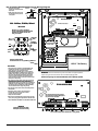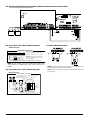
1
.
Light
Trouble
Light [1]
Service Required: Press [1] to determine the specific trouble. Lights 1 - 8 will light up to indicate the trouble:
• Light [1] Low Battery: Main panel backup battery charge is low (below 11.5 volts under load).Trouble is restored when the battery charges over
12.5 volts.
• Light [2] Bell Circuit Trouble: The bell circuit is open (see section 2.2 ’Terminal Descriptions’ ).
• Light [3] General System Trouble: One or more of the following troubles has occurred: the PC5204 Power Supply module has an AUX failure,
PC5204 Output #1 Trouble, Home Automation Trouble on the Escort5580(TC), or a printer connected to the PC5400 Printer module has a fault and
is off-line, or T-Link Troubles. Users can view specific conditions in the Event Buffer.
• Light [4] General System Tamper: Tamper has been detected from a module.
• Light [5] General System Supervisory: The panel has lost communication with a module connected to the Keybus (See section 2.8 ‘Confirming
Module Supervision‘ on page 8). The event buffer will log the event.
• Light [6] RF Jam: Please refer to the PC5132 Installation Manual for more information.
• Light [7] PC5204 Low Battery: The PC5204 module has a low backup battery.
• Light [8] PC5204 AC Failure: The PC5204 module has lost AC power.
NOTE: If you remove and then restore power to the main panel in order to service any PC5204 module, or any module being powered by a
PC5204, you must also remove and then restore power to the PC5204 and any connected modules. This ensures that any troubles present
on the module are correctly logged and/or annunciated.
Light [2]
AC Failure: AC power is no longer being supplied to the control panel. The Trouble light will flash if an AC Failure is present, if the Trouble Light
Flashes if AC Fails option is programmed (section [016], option [2]). This trouble will not be displayed if the AC Trouble Displayed option is disabled
(section [016], option [1]).
Light [3]
Telephone Line Monitoring Trouble (TLM): There is a problem with the telephone line. If the system has an Alternate Communicator, this trouble
can be reported to the central station by programming reporting codes in sections [345] and [346].
Light [4]
Failure to Communicate (FTC): The communicator failed to communicate with any of the programmed telephone numbers (see section 5.6 ‘Communicator Programming’).
Light [5]
Zone Fault (including Fire Zone): A zone on the system is experiencing trouble, meaning that a zone could not provide an alarm to the panel if
required to do so (e.g. a fire zone is open, or there is a short on a DEOL zone, or a supervisory fault on a wireless zone). When a zone fault occurs,
the keypad(s) on the system will start to beep. Press [5] while in Trouble mode to view the affected zones.
NOTE: A Fire zone trouble will be generated and displayed in the armed state.
Light [6]
Zone Tamper: A zone configured for Double End Of Line resistor supervision has a tamper condition, or the tamper switch is open on a wireless
device. When a tamper condition occurs, the keypad(s) will start to beep (if the system is armed, an alarm will occur). Press [6] while in the Trouble
mode to view the affected zones. If a zone is tampered or faulted, it must be fully restored to clear the trouble.
Light [7]
Device Low Battery/RF Delinquency: A wireless device has a low battery condition. Press [7] one, two, or three times to view which devices are
experiencing battery failure. Press the [7] key an additional time to view zones in RF Delinquency trouble. An LED keypad will indicate battery failure
using zone lights. The following will occur:
Keypad beeps:
Keypad displays:
Press [7]
1
Zones with low batteries (LED keypad - zone lights 1 to 32)
Press [7] again
2
Handheld keypads with low batteries (LED keypad - zone lights 1 to 4)
Press [7] again
3
Wireless keys with low batteries (LED keypad - zone lights 1 to 16)
Press [7] again
4
Zones in RF Delinquency trouble (LED keypad - zone lights 1 to 32)
Light [8]
Loss of System Time: When the panel is powered up, the internal clock needs to be set to the correct time. This trouble is cleared when an attempt
is made to reset the clock. This is set in [*][6] [Master Code] Programming on page 16.
Trouble Menu Acknowledgement
[*][4] Door Chime On/Off
If enabled the keypad will beep 6 times rapidly when a zone
is tripped and restored. The panel will only do this for zones
with the Door Chime attribute enabled and if the door chime
feature is enabled. The door chime attribute for each zone is
programmed in sections [101] to [164].
[*][5] Programming Access Codes
Access codes are required in order to perform various functions on the system such as arm, disarm, activate command
outputs etc.
EN
Press [9] for Trouble Menu Acknowledgement. This will
acknowledge and override existing troubles so the system
can be armed. An override event will also be generated and
logged, identifying the user. To override open zones, use the
Zone Bypass feature [*][1].
If a zone fault/tamper occurs, press [*][2][9] to override the
trouble, then [*][1] to override the open zone.
NOTE: When using the Trouble Menu Acknowledgement
feature, Section [022] Option 3 has to be enabled.
Program New Access Code
When using an LCD keypad, the trouble conditions will be
listed on the display. Users can scroll through the list of
present trouble conditions using the arrow (< >) keys.
NOTE: Troubles can be viewed while armed using the LCD
To program an access code enter [*][5][Master Code] followed by a two digit number corresponding to the access
code you want to program, then enter a new access code.
The available access codes are as follows:
keypad, provided the keypad is version 2.0 or later. Older
keypads will incorrectly display “Fire Trouble”. If using older
LCD keypads, program section [013], option [3] as OFF to
ensure that troubles are displayed correctly.
NOTE: If a trouble is present when the system is armed, the
trouble LED will remain on during Exit Delay but will turn off
once the exit delay timer expires.
General Access Codes - Access Codes [01] to [32]
Each access code can be used to arm and disarm the
assigned partitions. Additional access code attributes are
also programmable to determine what abilities the code will
have. You can program partition assignments and access
code attributes by following the instructions in this section.
[*][3] Alarm Memory
The ‘Memory’ light will be on if any alarm occurred during the
last armed period or if an alarm occurred while the panel
was disarmed (24 hour zones). Press [*][3] to view zones in
alarm memory. To clear the memory, arm and disarm the
system.
Supervisor Codes - Access Codes [41] and [42]
Supervisor Codes can program additional access codes. By
default, Supervisor codes have the same partition and
attribute programming as the Master code. You can change
the partition and attribute programming for these codes by
following the instructions in this section.
14