1
HM-60131-2
Data setting software
MEXE02 (Ver. 3.10 and later)
OPERATING MANUAL
Thank you for purchasing an Oriental Motor product.
This operating manual describes product handling procedures and safety precautions.
• Please read it thoroughly to ensure safe operation.
• Always keep the manual where it is readily available.
This manual describes the MEXE02 Ver. 3.10 and later.
The screens and operation procedures in the MEXE02 Ver. 3.10 and later
differ from those in versions earlier than the MEXE02 Ver. 3.10.
Please contact your nearest Oriental Motor branch or sales office for
further information.
Table of contents
1 MEXE02 supported product
function list ........................................... 4
2 Introduction..........................................11
3 Safety precautions.............................. 14
4 Startup and shutdown ........................ 15
4.1
4.2
4.3
Starting the MEXE02 ............................. 15
Shutting down ....................................... 15
Checking version information ................ 16
5 Data edit ............................................. 17
5.1
5.2
5.3
5.4
5.5
5.6
Creating new data ................................. 17
Opening an existing data file ................. 18
Setting data in the data edit window ..... 20
Saving a data file................................... 21
Data initialization ................................... 23
Ending data edit .................................... 24
6 Printing data ....................................... 25
6.1
6.2
6.3
How to print data ................................... 25
Print preview ......................................... 26
Setting print options .............................. 27
7 Communication function between
MEXE02 and applicable products....... 29
7.1
7.2
7.3
7.4
7.5
7.6
7.7
7.8
Connection with applicable product ...... 29
Setting of communication port............... 29
Online/Offline ........................................ 29
Writing data to applicable product ......... 30
Reading data from applicable product .. 31
Verifying data ........................................ 31
Resetting data of applicable product to
factory default settings .......................... 34
Checking the connected product........... 35
8 Setup function .................................... 36
8.1
8.2
8.3
8.4
8.5
8.6
8.7
−2−
Editing operation data ........................... 36
Editing parameters ................................ 37
Teaching/remote operation.................... 38
Remote operation.................................. 39
I/O test................................................... 40
Unit information monitor ........................ 41
System of units customize wizard ......... 42
9 Monitor function .................................. 44
9.1
9.2
9.3
9.4
9.5
9.6
Status monitor ....................................... 44
Status, I/O monitor ................................ 45
I/O monitor ............................................ 46
Remote register monitor........................ 49
RS-485 status monitor .......................... 50
Remote monitor..................................... 51
10 Adjustment functions .......................... 52
10.1 Waveform monitor ................................. 52
10.2 Gain tuning ............................................ 56
11 Diagnosis functions ............................ 58
11.1
11.2
11.3
11.4
Alarm monitor ........................................ 58
Warning monitor .................................... 60
RS-485 communication monitor ............ 61
Information monitor ............................... 63
12 Maintenance function ......................... 64
12.1
12.2
12.3
12.4
12.5
12.6
12.7
12.8
12.9
12.10
12.11
12.12
12.13
Clearing the HMI input .......................... 64
Executing Configuration ........................ 65
Backup function..................................... 65
Restore function .................................... 66
Mechanism Information copy ................ 67
Gear Information copy........................... 68
Coordinate Information copy ................ 68
Recommended macro operation copy .. 69
Batch copy of ABZO sensor information
(fixed value) to driver............................. 70
Position preset clear.............................. 71
ZSG preset clear ................................... 71
Latch information clear .......................... 72
Electronic damper ................................. 72
13 Utilizing MEXE02 ................................ 73
13.1
13.2
13.3
13.4
13.5
Operating motor using the MEXE02 ...... 73
Teaching software limit .......................... 77
Utilizing waveform monitor .................... 79
Checking wiring of applicable product... 84
Utilizing the warning function for when
writing data ............................................ 85
14 Troubleshooting .................................. 87
14.1 Checking error message ....................... 87
14.2 Frequently encountered errors .............. 88
License Agreement for Data Setting Software (MEXE02)
Please read the following terms and conditions carefully before using the Data Setting Software
(MEXE02) ("Software"). The user of the Software ("User") shall be deemed to agree to those terms and conditions
when the User makes the Software available for the use (including, but not limited to, download, installation and any
similar action), and this license agreement shall be deemed to be entered into between ORIENTAL MOTOR CO.,
LTD. ("ORIENTAL MOTOR") and the User.
1. The ownership right, copyright and other intellectual property right, and all other rights with regard to
the Software shall belong to either ORIENTAL MOTOR or its licensor, depending on the nature of each
specific right.
2. ORIENTAL MOTOR shall grant to the User a non-exclusive right to use the Software only for the
purpose of using an ORIENTAL MOTOR product or products supported by the Software.
3. The User may install and use one (1) copy of the Software in one (1) specific computer. If deemed
necessary, one (1) backup copy of the Software maybe created following installation.
4. The User may not reproduce, distribute, lend or transfer the Software to any third party or otherwise
allow any third party to use the Software in any form or by any means. Furthermore, the User may not
upload the Software to an electric bulletin board or website which is accessible by public.
5. The User may not modify, alter, reverse-engineer, decompile, disassemble or otherwise manipulate all
or part of the Software.
6. The User shall observe the Foreign Exchange and Foreign Trade Law and other applicable laws and
regulations related to export and import in Japan in using the Software. The User shall not export the
Software to any country which is subject to the export control regulations by the government of Japan
or USA.
7. Neither ORIENTAL MOTOR nor its licensor shall make any warranty as to whether the Software is
appropriate or useful in serving a specific purpose of the User, whether the Software is free from
defects, or any other condition relating to the Software.
8. Neither ORIENTAL MOTOR nor its licensor shall be held liable whatsoever for any loss or damage
arising directly or indirectly in association with, or in relation to, a use of the Software, including, but not
limited to, loss or damage arising from damage or corruption of hardware or software, loss of benefit,
disruption of business, loss of any data.
9. Neither ORIENTAL MOTOR nor its licensor shall be held liable whatsoever for any claim or demand
made by a third party regarding the Software.
10. ORIENTAL MOTOR shall reserve the right to change the specifications of the Software without prior
notice for the purpose of improvement.
11. This Agreement shall be terminated immediately upon the User's violation of this Agreement. The User
may not use the Software once this Agreement is terminated.
12. This Agreement shall be executed in both Japanese and English language, and in the event of any
conflicting terms, the Japanese version shall prevail.
13. This Agreement shall be governed by and interpreted in accordance with the Laws of Japan.
14. If any dispute arises out of this Agreement, the Tokyo District Court shall have exclusive jurisdiction to
settle such dispute for the first instance.
−3−
MEXE02 supported product function list
1 MEXE02 supported product
function list
The functions, setting items, and screens vary
depending on the product to be used in combination
with the MEXE02.
See the following function list or the USER MANUAL for
an applicable product to check the available functions.
AR Series
Function name
AZ Series
AC power
AC power input AC power input DC power input
input Built-in
DeviceNet
Pulse input
Pulse input
controller type
compatible
type
type
DC power
input Built-in
controller type
Operation data editing
−
−
Parameter setting
Teaching/remote operation
−
−
Remote operation
−
−
−
−
I/O test
Unit information monitor
−
−
−
−
−
Customize wizard
∗
−
−
−
−
−
Status monitor
−
−
−
−
−
Status, I/O monitor
−
D-I/O monitor, R-I/O monitor
−
−
−
−
−
Internal I/O monitor
−
−
−
Remote I/O monitor
−
−
−
−
−
−
Remote register monitor
−
−
−
−
−
−
RS-485 status monitor
−
−
−
−
−
−
Remote monitor
−
−
−
−
−
−
Waveform monitor
Gain tuning
−
−
−
−
−
−
Alarm monitor
Warning monitor
−
RS-485 communication
monitor
−
−
−
Information monitor
−
−
−
−
−
HMI-CLR
−
−
−
−
−
Configuration execution
−
−
−
−
−
Restore function
−
−
−
−
−
Backup function
−
−
−
−
−
Mechanism information copy
−
−
−
−
−
Gear information copy
−
−
−
−
−
Coordinate information copy
−
−
−
−
−
Recommended macro
−
−
−
−
−
operation copy
* It cannot be used depending on the motor types or actuator types to be connected. In this case, the recommended setting support is
automatically applied.
−4−
MEXE02 supported product function list
ARL Series
Built-in controller type
CC-Link compatible
1 station
occupied
BASIC mode
2 station
occupied
ADVANCED
mode
2 station
occupied
BASIC mode
−
−
1 station
occupied
ADVANCED
mode
MECHATROLINK-Ⅱ
compatible
Controller mode
−
−
−
−
−
−
−
−
−
−
−
−
−
−
−
−
−
−
−
−
−
−
Driver mode
−
−
−
−
−
−
−
−
−
−
−
−
−
−
−
−
−
−
−
−
−
−
−
−
−
−
−
−
−
−
−
−
−
−
−
−
−
−
−
−
−
−
−
−
−
−
−
−
−
−
−
−
−
−
−
−
−
−
−
−
−
−
−
−
−
−
−
−
−
−
−
−
−
−
−
−
−
−
−
−
−
−
−
−
−
−
−
−
−
−
−
−
−
−
−
−
−
−
−
−
−
−
−
−
−
−
−
−
−
−
−
−
−
−
−
−
−
−
−
−
−
−
−
−
−
−
−
−
−
−
−
−
−
−
−5−
MEXE02 supported product function list
AR Series
Function name
AZ Series
Batch copy of ABZO sensor
information (fixed value) to
driver
−
−
−
−
−
Position preset clear
−
−
−
−
−
ZSG preset clear
−
−
−
−
−
Latch information clear
−
−
−
−
−
−6−
AC power
AC power input AC power input DC power input
input Built-in
DeviceNet
Pulse input
Pulse input
controller type
compatible
type
type
DC power
input Built-in
controller type
MEXE02 supported product function list
ARL Series
Built-in controller type
CC-Link compatible
1 station
occupied
ADVANCED
mode
1 station
occupied
BASIC mode
2 station
occupied
ADVANCED
mode
2 station
occupied
BASIC mode
MECHATROLINK-Ⅱ
compatible
Controller mode
Driver mode
−
−
−
−
−
−
−
−
−
−
−
−
−
−
−
−
−
−
−
−
−
−
−
−
−
−
−
−
−7−
MEXE02 supported product function list
The functions, setting items, and screens vary
depending on the product to be used in combination
with the MEXE02.
See the following function list or the USER MANUAL for
an applicable product to check the available functions.
NX Series
Function name
PKA Series
RKⅡ Series
Built-in
controller
type
Built-in
controller
type
Position control
mode
Speed control
mode
Operation data editing
Parameter setting
Teaching/remote operation
−
−
−
−
Remote operation
−
−
I/O test
Unit information monitor
−
−
−
−
−
−
Customize wizard
−
−
−
−
−
−
Status monitor
−
−
−
−
−
−
Status, I/O monitor
D-I/O monitor, R-I/O monitor
−
−
−
−
−
−
Internal I/O monitor
−
−
−
−
Remote I/O monitor
−
−
−
−
−
−
Remote register monitor
−
−
−
−
−
−
RS-485 status monitor
−
−
−
−
−
−
Remote monitor
−
−
−
−
−
−
Waveform monitor
Gain tuning
−
−
−
−
Alarm monitor
Warning monitor
RS-485 communication
monitor
−
−
−
−
Information monitor
−
−
−
−
−
−
HMI-CLR
−
−
−
−
−
−
Configuration execution
−
−
−
−
−
−
Restore function
−
−
−
−
−
−
Backup function
−
−
−
−
−
−
Mechanism information copy
−
−
−
−
−
−
Gear information copy
−
−
−
−
−
−
Coordinate information copy
−
−
−
−
−
−
Recommended macro
operation copy
−
−
−
−
−
−
Batch copy of ABZO sensor
information (fixed value) to
driver
−
−
−
−
−
−
Position preset clear
−
−
−
−
−
−
ZSG preset clear
−
−
−
−
−
−
Latch information clear
−
−
−
−
−
−
−8−
Torque control Tension control
mode
mode
MEXE02 supported product function list
BXⅡ Series
BLE Series
CC-Link
compatible
Standard/
electromagnetic
brake type
RS-485
communication
type
Speed control
mode
Position control
mode
BX compatible
mode (speed
control)
BX compatible
mode (position
control)
−
−
−
−
−
−
−
−
−
−
−
−
−
−
−
−
−
−
−
−
−
−
−
−
−
−
−
−
−
−
−
−
−
−
−
−
−
−
−
−
−
−
−
−
−
−
−
−
−
−
−
−
−
−
−
−
−
−
−
−
−
−
−
−
−
−
−
−
−
−
−
−
−
−
−
−
−
−
−
−
−
−
−
−
−
−
−
−
−
−
−
−
−
−
−
−
−
−
−
−
−
−
−
−
−
−
−
−
−
−
−
−
−
−
−
−
−
−
−
−
−
−
−
−
−
−
−
−
−
−
−
−
−
−
−
−
−
−
−
−
−
−
−
−
−
−
−
−
−
−
−
−
−
−
−
−
−
−
−
−
−
−
−
−
−
−
−
−9−
MEXE02 supported product function list
The functions, setting items, and screens vary
depending on the product to be used in combination
with the MEXE02.
See the following function list or the USER MANUAL for
an applicable product to check the available functions.
CRK Series DRLⅡ Series
Network converter
Built-in
controller
type
Built-in
controller
type
Operation data editing
−
−
−
−
Parameter setting
Teaching/remote operation
−
−
−
−
Function name
CC-Link MECHATROLINK-Ⅱ MECHATROLINK-Ⅲ EtherCAT
compatible
compatible
compatible
compatible
Remote operation
−
−
−
−
−
−
I/O test
−
−
−
−
Unit information monitor
−
−
−
−
−
−
Customize wizard
−
−
−
−
−
−
Status monitor
−
−
−
−
−
−
Status, I/O monitor
−
−
−
−
D-I/O monitor, R-I/O
monitor
−
−
−
−
−
−
Internal I/O monitor
−
−
−
−
−
−
Remote I/O monitor
−
−
Remote register monitor
−
−
RS-485 status monitor
−
−
Remote monitor
−
−
−
−
−
Waveform monitor
−
−
−
−
Gain tuning
−
−
−
−
−
−
Alarm monitor
Warning monitor
RS-485 communication
monitor
−
−
−
−
Information monitor
−
−
−
−
−
−
HMI-CLR
−
−
−
−
−
−
Configuration execution
−
−
−
−
−
−
Restore function
−
−
−
−
−
−
Backup function
−
−
−
−
−
−
Mechanism information
copy
−
−
−
−
−
−
Gear information copy
−
−
−
−
−
−
Coordinate information
copy
−
−
−
−
−
−
Recommended macro
operation copy
−
−
−
−
−
−
Batch copy of ABZO sensor
information (fixed value) to
driver
−
−
−
−
−
−
Position preset clear
−
−
−
−
−
−
ZSG preset clear
−
−
−
−
−
−
Latch information clear
−
−
−
−
−
−
−10−
Introduction
2 Introduction
This manual describes the MEXE02 Ver. 3.10 and later.
The screens and operation procedures in the MEXE02 Ver. 3.10 and later
differ from those in versions earlier than the MEXE02 Ver. 3.10.
Please contact your nearest Oriental Motor branch or sales office for further
information.
Before Use
Perform any installation, uninstallation, editing, and other operations for the data setting software MEXE02 using an
account with Administrator privileges.
Use the MEXE02 correctly and safely after thoroughly reading the manual and understanding the basic operating
procedures and other details.
Applicable product
The MEXE02 can be used with Oriental Motor's stepping motor drivers, servo motor drivers, brushless motor drivers,
and network converters etc.
A product that can be combined with the MEXE02 is described as "applicable product" here.
Notation rules
The description of text in this manual follows the notation
rules specified as shown at the right. The screens shown
in this manual are those displayed in Windows 7. The
screens vary according to the operating systems (OS) you
will be using.
[
]
Menus and submenus shown in/from the
title bar, buttons, and other controls that can
be clicked with the mouse, are enclosed in
square brackets.
"
"
Dialog box messages, etc., are enclosed in
double quotations marks.
Functions of MEXE02
The MEXE02 is a software program that lets you set data required for motor operation from a PC.
Data can be edited in various PC screens, or data set in an applicable product can be checked from a PC.
The key functions of the MEXE02 are explained below.
• Editing and saving the data
Operation data and parameters can be created and edited.
Data edited in the MEXE02 can be written to an applicable product, or data stored in an applicable product can be
read into the MEXE02.
You can save data files created in the MEXE02 in either the MEXE02’s dedicated file format or CSV format.
• Monitor function
You can monitor the product (motor and driver) status, motor operating status, ON/OFF status of I/O signals, and
others.
The waveform monitor lets you check I/O signals, motor speeds and other settings based on measured waveforms.
• Test function
y I/O test can be performed to monitor input signals and cause output signals to be output forcibly.
y Test operation for the motor can be performed using the teaching/remote operation or remote operation.
Installation and uninstallation of MEXE02
For the installation and uninstallation of the MEXE02, refer to Oriental Motor Website or the separate manual "Data
Setting Software MEXE02 INSTALLATION MANUAL.
−11−
Introduction
Communication cables
Communication cables vary depending on the applicable product. Check the USER MANUAL of the applicable
product.
• When using a USB cable
Use a commercially available USB cable.
• When using the CC05IF-USB communication cable for data setting software
The CC05IF-USB supplied communication cable for data setting software consists of a pair of cables, PC interface
cable and USB cable. If the MEXE02 has been downloaded from the Oriental Motor Website, note that this cable is
sold separately (as an accessory).
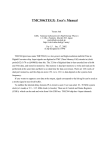
General specifications of CC05IF-USB
Interface
USB Specification 1.1 (Full Speed 12 Mbps)
Connector shapes
RS-485 (Mini DIN 8 Pin: male), USB (Type Mini B: female)
USB Type A connection via included USB cable to connect to a PC
Communication system
Half duplex
Communication speed
9600 bps
Indicator
The LED is lit (green) when recognized by PC and ready to use.
Power supply
USB bus power
Current consumption
25 mA (100 mA max.)
Dimension
25×58.6×16 mm (0.98×2.31×0.63 in.) [excluding cable section]
Mass
PC interface cable: App. 0.2 kg (7.1 oz)
USB cable: App. 0.03 kg (1.06 oz)
Operating environment
Ambient temperature: 0 to +40 °C (+32 to +104 °F) (non-freezing)
Ambient humidity: 85% or less (non-condensing)
Atmosphere: No corrosive gas, dust, water or oil
Insulation system
Non-isolated
System requirements
The installation of the MEXE02 on a PC requires one of the following operating systems (OS) and a PC compatible
with the OS you will be using.
• PC
Recommended CPU ∗1
Intel Core processor 2 GHz or higher (Your operating system must support the OS.)
Display
Video adapter or monitor of XGA (1024×768) or higher resolution
Recommended memory
32-bit (x86) version: 1 GB or more
64-bit (x64) version: 2 GB or more
Hard disk ∗2
Available disk space of 60 MB or more
USB port
Using USB cable: One USB2.0 port
Using CC05IF-USB: One USB1.1 port
Disk drive
CD-ROM drive (for installation)
*1 The hardware requirements for the OS must be satisfied.
*2 Microsoft .NET Framework 4 Client Profile must be installed in your PC for the MEXE02 to function. It will be installed
automatically, if not already installed. Accordingly, additional free hard disk space shown below may be required.
32-bit (x86) version: 600 MB
64-bit (x64) version: 1.5 GB
Note
The required memory and hard disk space may vary depending on your system environment.
• Operating System (OS)
Both the 32-bit (x86) and 64-bit (x64) versions are supported.
y Microsoft Windows XP Service Pack 3 [Service Pack 2 for 64-bit (x64) version]
y Microsoft Windows Vista Service Pack 2
y Microsoft Windows 7 Service Pack 1
y Microsoft Windows 8
y Microsoft Windows 8.1
−12−
Introduction
Checking the product
Verify that the items listed below are included in the MEXE02 that you purchased. Report any missing or damaged
items to the branch or sales office from which you purchased the product.
y Data setting software MEXE02 (CD-ROM) ............................................ 1 pc.
y Communication cable for the data setting software CC05IF-USB ......... 1 set
(one PC interface cable and one USB cable)
y OPERATING MANUAL (CD-ROM) ...................................................... 1 pc.
y INSTALLATION MANUAL .................................................................... 1 copy
Hazardous substances
The products do not contain the substances exceeding the restriction values of RoHS Directive (2011/65/EU).
−13−
Safety precautions
3 Safety precautions
The MEXE02 is designed with the assumption that the user has an understanding of basic operations such as starting
up and exiting applications and how to use a mouse in Windows XP, Windows Vista, Windows 7, and Windows 8. Use
the product only after carefully reading and fully understanding these instructions.
Also read the "Safety precautions" section in the USER MANUAL for the product to be used in combination with the
MEXE02.
Handling the product without observing the instructions that accompany a "Warning" symbol may result in serious
injury or death.
Connection
y Turn off the power to both the PC and applicable product before connecting your PC to the applicable product.
Failure to follow this instruction may cause electric shock.
Handling the product without observing the instructions that accompany a "Caution" symbol may result in injury or
property damage.
Connection
y The data setter connector of the applicable product is not insulated. When grounding the positive terminal of the
power supply, do not connect any equipment (PC, etc.) whose negative terminal is grounded. Doing so may cause
the equipment and applicable product to short, damaging both. Do not ground the equipment if you plan to connect
it.
Disposal
y To dispose of the MEXE02, disassemble it into parts and components as much as possible, and dispose of
individual parts/components as industrial waste.
−14−
Startup and shutdown
4 Startup and shutdown
This chapter explains how to start up and shut down the MEXE02.
4.1
Starting the MEXE02
Double-click the MEXE02 icon on the desktop to start the MEXE02.
Once the MEXE02 has started, the following window appears.
4.2
Shutting down
Click [Exit] from the [File] menu. Alternatively, click the button on the upper right of the screen.
The MEXE02 shuts down.
−15−
Startup and shutdown
4.3
Checking version information
You can check the version of the MEXE02 software you are using.
1. Click [About MEXE02] from the [Help] menu.
2. After you have checked the software version, click [Close].
The software version is also found on the MEXE02 CD-ROM.
−16−
Data edit
5 Data edit
This chapter explains how to create data files, edit operation data and parameters, and store edited data.
5.1
Creating new data
1. Click the [New] icon in the toolbar.
2. Select a model from "Product Series List" and "Product Name (Mode) List," and click [OK].
In the case of actuators, select the series name of the motor that is equipped to the actuator.
1
2
4
3
5
1
[OK] button
Clicking [OK] after selecting a model will show the data edit
window.
2
[System of Units Customize Wizard]
start button
This button starts a wizard to display or enter the travel
distance or speed for the selected model by a desired unit.
(Some models are not supported.) Refer to p.42 for details.
3
[Search model] button
Clicking [Search model] after connecting an applicable
product and selecting the series name will automatically
select the model.
4
• Product Series List
• Product Name (Mode) List
• Motor/Actuator
5
Selection Log
A desired model can be selected from the displayed
products.
A list of previously selected models is displayed. You can
also select a model from this list.
−17−
Data edit
The data edit window appears.
5.2
Opening an existing data file
1. Click the [Open] icon in the toolbar.
2. Select the file you want to edit, and click [Open].
−18−
Data edit
The data edit window appears, just like when you are creating a new data file.
Description of edit window
1
2
3
5
4
1
Menu bar
This is used to select and execute a function.
2
Tool bar
Some of the functions available on the menu are provided as an array of
icons.
3
Tree view
This is used to select a group of data for editing.
4
Short-cut buttons
Using these buttons, functions such as monitor and test can be executed. The
functions in this area can also be executed from the [Tool] menu.
5
Data setting area
This is an area to edit data. The display is changed by selecting a group from
the tree view.
−19−
Data edit
5.3
Setting data in the data edit window
Note
• Changing the data in the MEXE02 will not change the data in the applicable product. Data
writing is required to change the data in the applicable product. Refer to p.30 for details.
• Data cannot be edited while communicating with the applicable product using the monitor or test
function. Edit data after ending the communication.
Data entry
The background color of a cell is initially white. When the value in the cell is changed, the color of the cell changes to
yellow.
The color of characters in the cell is initially blue. When the value in the cell is changed, the color of characters
changes to black.
• Entering characters
Click a cell and enter characters using the keyboard.
Note
Do not enter a comma (,) in the "Name" field of the operation data. Entering a comma may cause
a problem in the subsequent data edit.
• Entering a numeric value
Click a desired cell, and enter a numeric value using the keyboard.
• Selecting a value from a pull-down menu
Double-clicking a desired cell displays a pull-down menu. Select a desired value from the pull-down menu.
Copying and pasting data
You can copy an entered value and paste it into a different cell. Copying and pasting lets you quickly populate
multiple cells with the same value.
1. Select the data you want to copy, and then click the [Copy] icon in the toolbar.
You can select a single value or multiple values.
Data to be copied
2. Click the cell you want to paste the data into, and then click the [Paste] icon in the toolbar.
Destination cell
−20−
Data edit
Undoing and redoing
1. To undo the last edit that you made, click the [Undo] icon in the toolbar.
2. To redo the last edit that was undone, click the [Redo] icon in the toolbar.
Note
• [Undo] operation cannot execute:
- When communicating with the applicable product
- When no edit has been done yet.
• [Redo] operation cannot execute:
- When no [Undo] has been done yet.
5.4
Saving a data file
The data edited within the MEXE02 or data read by the applicable product will be saved as a file.
Data files can be saved in the MEXE02 format (.mx2), MEXE02 extended format (.mx2a), or CSV format (.csv).
Data files saved in the MEXE02 format and MEXE02 extended format cannot be opened in other applications. Save
data files in the CSV format if you want to open them in other applications.
Saving data by overwriting
Click the [Save] icon in the toolbar.
The current data is saved over the existing data.
Saving data under a different name
1. Click [Save As] from the [File] menu.
−21−
Data edit
2. Enter a new file name, and click [Save].
The data is saved under the specified name.
Note
If the data, which has been saved in the MEXE02 extended format (.mx2a), will be saved in the
MEXE02 format (.mx2) again, the extended information will be erased. Be sure to check the
saving format (filename extension) beforehand.
Saving data in CSV format
Data saved in the CSV format can be edited in applications other than the MEXE02.
Note
Data files in the CSV format cannot be opened in the MEXE02. To edit in the MEXE02, open the
file in an application other than the MEXE02, and paste the data to the MEXE02.
1. Click [Export] from the [File] menu.
−22−
Data edit
2. Enter a file name, and click [Save].
All operation data and parameters are saved in CSV format.
5.5
Data initialization
Initialize editing data
You can initialize the data you have edited in the data edit window.
1. Click [Initialize] from the [Edit] menu.
2. Select the data you want to initialize,
and click [OK].
3. Click [Yes].
The data is initialized.
−23−
Data edit
Initializing data in selected cells
1. In the data edit window, select the cell you want to
initialize.
2. Click the right mouse button, and click [Initialize].
The value in the selected cell returns to the default.
5.6
Ending data edit
To close the data edit window, click [Close] from the [File]
menu.
−24−
Printing data
6 Printing data
This chapter explains how to print the set data and waveform measurement results.
6.1
How to print data
1. Click [Print] from the [File] menu.
2. Set the print item, print object and color, and click [Run].
3. At "Name," select a printer that you want to use for printing and click [OK].
Data is printed.
−25−
Printing data
6.2
Print preview
You can preview the print image on screen before printing it on the printer.
1. Click [Print Preview] from the [File] menu.
Alternatively, click [Print] from the [File] menu and, in the window
that opens, execute print preview.
The print preview window appears.
2. After checking the print image, click [Close].
−26−
Printing data
6.3
Setting print options
1. Click [Page Setup] from the [File] menu.
2. Click the tab of an option that you want to set.
After the setting is completed, click [OK].
• "Page" tab
Set the orientation, paper, etc. to be used for printing.
−27−
Printing data
• "Margin" tab
Set the paper margin and header/footer positions.
• "Header/Footer" tab
Set the header/footer.
−28−
Communication function between MEXE02 and applicable products
7 Communication function between
MEXE02 and applicable products
This chapter explains how to hold communication between the MEXE02 and an applicable product to write or read
data.
7.1
Connection with applicable product
1. Connect the PC on which the MEXE02 has been installed and an applicable product.
Read the USER MANUAL of the applicable product to connect it correctly.
Refer to p.12 for the communication cable.
2. Turn on the power to the applicable product.
7.2
Setting of communication port
When connecting the PC and applicable product, the communication port is required to set.
1. Click [Setting of the Communication] from the
[Communication] menu.
2. Select the port to which the applicable product is
connected and click [OK].
When connecting using the USB cable: "ORIENTAL
MOTOR/Common Virtual COM Port" is displayed.
When connecting using the CC05IF-USB: "ORIENTAL
MOTOR/Virtual COM Port" is displayed.
Note
7.3
Before setting the communication port, make sure to connect the PC and applicable product and
turn on the power of the applicable product. Without proper connection, the connection port will not
be displayed.
Online/Offline
The PC and applicable product is started connecting.
1. Click the [Online] icon in the toolbar.
The [Online] icon is depressed and the PC and
applicable product are connected (online).
2. To clear the connection, click the [Offline] icon.
Note
• When the monitor function or test function is executed, the PC and applicable product are
automatically connected (online).
• Clicking the [Offline] icon stops the monitor function or test function that is conducting
communication.
−29−
Communication function between MEXE02 and applicable products
7.4
Writing data to applicable product
The data created in the MEXE02 can be written to the applicable product.
Note
Do not turn off the power of the applicable product while writing data. Doing so may destroy the
data.
1. Click the [Data writing] icon in the toolbar.
2. Select data to be written and click [OK].
3. Click [Yes].
Data writing starts.
4. If the following message is displayed, click
either [Yes] or [No] after checking the applicable
product.
[Yes]: Writing data will be started.
[No]: Writing data will be discontinued.
5. After it is completed, click [OK].
Note
Depending on the data, you may need to turn off and on the power or execute Configuration.
Follow the instructions in the displayed messages.
• Restarting power
−30−
• Executing Configuration
Click [Yes] to execute Configuration.
If you click [No], execute Configuration manually.
Refer to p.65 for details.
Communication function between MEXE02 and applicable products
7.5
Reading data from applicable product
The data saved in an applicable product can be read to the MEXE02.
1. Click the [Data reading] icon in the toolbar.
2. If the data is being edited in the MEXE02, a confirmation
message for saving the data is shown.
Click [Yes] to save the edited data or [No] not to save it.
Note
If you select [No], the data under editing is cleared
and overwritten with the data to be read.
3. Click [OK].
Data reading starts.
4. After it is completed, click [OK].
The screen shows the data that has been read.
7.6
Verifying data
The data saved in the applicable product can be verified against the data displayed in the MEXE02.
1. Click the [Data verification] icon in the toolbar.
2. Select the data to be verified, and then click [OK].
Data is verified.
−31−
Communication function between MEXE02 and applicable products
The results are displayed after the completion of verification.
3. After checking the verification results, click [Close].
Copying verification results
The verification results can be copied to the clipboard by clicking the right mouse button on the area that displays the
results and clicking [Copy Results to Clipboard]. The copied data can be pasted to other applications.
Note
−32−
Nothing is copied if the data completely matches.
Communication function between MEXE02 and applicable products
Jumping to desired data from verification results
You can jump from the list of verification results to the edit window for the displayed data.
1. Select and double-click data that you want to edit.
The window for editing the desired data appears.
2. Click [Close].
−33−
Communication function between MEXE02 and applicable products
7.7
Resetting data of applicable product to factory default settings
The data saved in the non-volatile memory of the applicable product can be reset to the factory default settings.
Note
Do not turn off the power of the applicable product while initializing. Doing so may destroy the data.
1. Click [Reset] from the [Communication] menu.
2. Select data that you want to reset to the factory
default settings and click [OK].
3. Click [Yes].
The data saved in the non-volatile memory of the
applicable product will be reset to the factory default
settings.
4. After it is completed, click [OK].
Note
Depending on the data, you may need to turn off and on the power or execute Configuration.
Follow the instructions in the displayed messages.
• Restarting power
−34−
• Executing Configuration
Click [Yes] to execute Configuration.
If you click [No], execute Configuration manually.
Refer to p.65 for details.
Communication function between MEXE02 and applicable products
7.8
Checking the connected product
1. Click [Device Information] from the [Tool] menu.
2. Click [Check].
The check on the connected product starts.
3. When the results are displayed, click [Close].
• When the series name or product name (mode) of the applicable product is not displayed:
Verify the following points:
y Is the applicable product powered on?
y Is the cable completely inserted?
y Is the connected product compatible with the MEXE02?
• When "Unsupported Product" is shown in the product name column.
Verify that the connected product is compatible with the MEXE02.
−35−
Setup function
8 Setup function
This chapter explains the functions mainly used to start up an applicable product.
8.1
Editing operation data
The operation data of an applicable product can be edited using the MEXE02.
If "Data writing" is executed, the edited data can be written to the applicable product. Refer to p.30 for details.
1. Open the data edit window.
2. Click [Operation data] on the tree view.
The operation data edit window appears.
Refer to "5 Data edit" on p.17 for how to edit data and other information.
−36−
Setup function
8.2
Editing parameters
The parameters of an applicable product can be edited using the MEXE02.
If "Data writing" is executed, the edited data can be written to the applicable product. Refer to p.30 for details.
1. Open the data edit window.
2. Click a parameter group that you want to edit
from the tree view.
The parameter edit window appears.
Refer to "5 Data edit" on p.17 for how to edit data and other information.
−37−
Setup function
8.3
Teaching/remote operation
A motor can be operated using the MEXE02. This function lets you check how the motor will operate before actually
connecting it to a programmable controller. Operation data can also be set using teaching function.
Note
The teaching/remote operation and I/O test cannot be executed simultaneously.
1. Click the [Teaching, remote operation] icon in the toolbar or click the [Teaching, remote operation] shortcut button.
or
The teaching/remote operation window appears.
2. Click "Start the teaching remote operation."
3. Click [Yes].
The teaching/remote operation is enabled.
The teaching/remote operation requires synchronization of the
data under editing and the data of an applicable product. When the
data is not synchronized, the following window appears. Select a
synchronization method and click [OK].
Note
When the above window appears, all the communications in progress are disabled. All
the other monitors in progress in other windows are also stopped. Resume monitor after
synchronization is completed.
4. To end the teaching/remote operation, unselect "Start the teaching remote operation."
−38−
Setup function
8.4
Remote operation
A motor can be operated using the MEXE02. This function lets you check how the motor will operate before actually
connecting it to a programmable controller.
Note
The remote operation and I/O test cannot be executed simultaneously.
1. Click the [Remote operation] icon in the toolbar or click the [Remote operation] short-cut button.
or
The remote operation window appears.
2. Click "Start the remote operation."
3. Click [Yes].
The remote operation is enabled.
The remote operation requires synchronization of the data under
editing and the data of an applicable product. When the data
is not synchronized, the following window appears. Select a
synchronization method and click [OK].
Note
When the above window appears, all the communications in progress are disabled. All
the other monitors in progress in other windows are also stopped. Resume monitor after
synchronization is completed.
4. To end the remote operation, unselect "Start the remote operation."
−39−
Setup function
8.5
I/O test
I/O signals of direct I/O and remote I/O can be tested. Also, you can monitor input signals and cause output signals to
be output forcibly.
This function is convenient if you want to check the wire connection of physical I/O with the programmable controller
and the operation of network I/O.
Note
• In I/O test, you can forcibly turn on or off output signals. Consequently, other equipment
connected to an applicable product may operate. Check the surrounding circumstances to
ensure safety before conducting this procedure.
• The teaching/remote operation and I/O test cannot be executed simultaneously.
1. Click the [Test I/O] icon in the toolbar or click the [Test I/O] icon.
or
The I/O test window appears.
2. Click "Start I/O Test."
3. Click [Yes].
You can now perform I/O test.
4. Switch the ON/OFF status of input signals externally.
The check box of the corresponding "INPUT" is changed in the window.
Indicator
Direct I/O
Remote I/O
(RS-485 communication)
ON (green)
Conducting
Active
OFF (white)
Non-conducting
Not active
5. When switching the ON/OFF status of output signals, click the check box of "OUTPUT" in the
window.
Indicator
Direct I/O
Remote I/O
(RS-485 communication)
ON (green)
Conducting
Active
OFF (white)
Non-conducting
Not active
6. To end the I/O test, unselect "Start I/O Test."
−40−
Setup function
8.6
Unit information monitor
You can monitor the product information of an applicable product.
1. Click the [Unit information monitor] icon in the toolbar or click the [Unit information monitor] short-cut
button.
or
The unit information monitor window appears.
2. Click "Start the Unit information monitor."
The unit information monitor starts.
3. To exit the monitor, unselect "Start the Unit information monitor."
−41−
Setup function
8.7
System of units customize wizard
The system of units customize wizard is a function to display or enter the travel distance, speed, and others by a
desired unit.
Follow the instructions in the displayed window to proceed with the setting.
2
1
3
−42−
4
5
6
7
1
List of setting items
The current setting item is displayed in boldface type.
Clicking an item will change the setting area.
2
Setting area
The setting can be performed by following the instructions in the window.
3
[Restore Defaults]
This button is used to restore the setting item to a value before the change.
4
[Back]
This button is used to switch the currently displayed item to the previous item.
5
[Next]
This button is used to switch the currently displayed item to the next item.
6
[Finish]
This button is used to exit the wizard. It is possible to exit the wizard before the
setting is completed. A warning is displayed if there is an error in the setting item.
7
[Cancel]
This button is used to stop the setting in the wizard. The changed values are not
applied.
Setup function
After the setting is completed using the wizard, the window is shown as below.
1
2
3
1
[System of Units
Customize Wizard]
This button is used to start the wizard with the current settings applied.
2
unit of display
A system of units is selected. It is also possible to change using the wizard.
3
Parameter
Numeric values can be displayed in the selected system of units. The selected
system of units is also used when entering values.
−43−
Monitor function
9 Monitor function
This chapter explains how to check the status of an applicable product using the MEXE02.
9.1
Status monitor
You can monitor the current status of an applicable product.
1. Click the [Status monitor] icon in the toolbar or click the [Status monitor] short-cut button.
or
The status monitor window appears.
2. Click "Start Status Monitor."
Status monitor starts.
3. To end status monitor, unselect "Start Status Monitor."
−44−
Monitor function
9.2
Status, I/O monitor
You can monitor the current status of an applicable product and the ON/OFF status of I/O signals.
1. Click the [Status, I/O monitor] icon in the toolbar or click the [Status, I/O monitor] short-cut button.
or
The status, I/O monitor window appears.
2. Click "Start the Status, I/O monitor."
The status, I/O monitor starts.
The ON/OFF status of I/O signals is displayed as shown below.
Indicator
I/O
ON (green)
Conducting
RS-485 communication
Active
OFF (white)
Non-conducting
Not active
The status, I/O monitor requires synchronization of the data under
editing and the data of an applicable product. When the data is not
synchronized, the following window appears. Select a synchronization
method and click [OK].
Note
When the above window appears, all the communications in progress are disabled. All
the other monitors in progress in other windows are also stopped. Resume monitor after
synchronization is completed.
3. To exit the monitor, unselect "Start the Status, I/O monitor."
−45−
Monitor function
9.3
I/O monitor
D-I/O monitor, R-I/O monitor
You can monitor the ON/OFF status of I/O signals of an applicable product.
D-I/O represents direct I/O, and R-I/O represents remote I/O (controlled via RS-485 communication).
1. Click the [D-I/O, R-I/O monitor] icon in the toolbar or click the [D-I/O, R-I/O monitor] short-cut button.
or
The D-I/O, R-I/O monitor window appears.
2. Click "Start the D-I/O, R-I/O monitor."
The D-I/O, R-I/O monitor starts.
The ON/OFF status of I/O signals is displayed as shown below.
Indicator
Direct I/O
Remote I/O
(RS-485 communication)
ON (green)
Conducting
Active
OFF (white)
Non-conducting
Not active
3. To exit the monitor, unselect "Start the D-I/O, R-I/O monitor."
−46−
Monitor function
Internal I/O monitor
All the I/O signals of an applicable product can be monitored. You can also check signals not assigned to direct I/O or
remote I/O.
1. Click the [Internal I/O monitor] icon in the toolbar or click the [Internal I/O monitor] short-cut button.
or
The internal I/O monitor window appears.
2. Click "Start the Internal I/O monitor."
The internal I/O monitor starts.
The ON/OFF status of I/O signals is displayed as shown below.
Indicator
Internal signal status
ON (green)
Active
OFF (white)
Not active
3. To exit the monitor, unselect "Start the Internal I/O monitor."
−47−
Monitor function
Remote I/O monitor
You can check the ON/OFF status of network I/O.
1. Click the [Remote I/O monitor] icon in the toolbar or click the [Remote I/O monitor] short-cut button.
or
The remote I/O monitor window appears.
2. Click "Start Remote I/O Monitor."
The remote I/O monitor starts.
The ON/OFF status of I/O signals is displayed as shown below.
Indicator
Remote I/O
(RS-485 communication)
ON( green)
Active
OFF (white)
Not active
The remote I/O monitor requires synchronization of the data
under editing and the data of an applicable product. When the
data is not synchronized, the following window appears. Select a
synchronization method and click [OK].
Note
When the above window appears, all the communications in progress are disabled. All
the other monitors in progress in other windows are also stopped. Resume monitor after
synchronization is completed.
3. To exit the monitor, unselect "Start Remote I/O Monitor."
−48−
Monitor function
9.4
Remote register monitor
You can monitor the remote register status that can be read and written to via a network.
1. Click the {Remote Register Monitor] icon in the toolbar or click the [Remote Register Monitor] short-cut
button.
or
The remote register monitor window appears.
2. Click "Start Remote Register Monitor."
The remote register monitor starts.
The remote register monitor requires synchronization of the data
under editing and the data of an applicable product. When the
data is not synchronized, the following window appears. Select a
synchronization method and click [OK].
Note
When the above window appears, all the communications in progress are disabled. All
the other monitors in progress in other windows are also stopped. Resume monitor after
synchronization is completed.
3. To exit the monitor, unselect "Start Remote Register Monitor."
−49−
Monitor function
9.5
RS-485 status monitor
You can monitor the RS-485 communication status of an applicable product.
1. Click the [RS-485 status monitor] icon in the toolbar or click the [RS-485 status monitor] short-cut
button.
or
The RS-485 status monitor window appears.
2. Click "Start RS-485 Status Monitor."
The RS-485 status monitor starts.
The RS-485 status monitor requires synchronization of the data
under editing and the data of an applicable product. When the
data is not synchronized, the following window appears. Select a
synchronization method and click [OK].
Note
When the above window appears, all the communications in progress are disabled. All
the other monitors in progress in other windows are also stopped. Resume monitor after
synchronization is completed.
3. To exit the monitor, unselect "Start RS-485 Status Monitor."
−50−
Monitor function
9.6
Remote monitor
You can monitor the data sent and received between an applicable product and programmable controller.
1. Click the [Remote monitor] icon in the toolbar or click the [Remote monitor] short-cut button.
or
The remote monitor window appears.
2. Click "Start remote monitor."
The remote monitor starts.
The remote monitor requires synchronization of the data under
editing and the data of an applicable product. When the data
is not synchronized, the following window appears. Select a
synchronization method and click [OK].
Note
When the above window appears, all the communications in progress are disabled. All
the other monitors in progress in other windows are also stopped. Resume monitor after
synchronization is completed.
3. To exit the monitor, unselect "Start remote monitor."
−51−
Adjustment functions
10 Adjustment functions
This chapter explains how to adjust an applicable product using the MEXE02.
10.1 Waveform monitor
The motor speeds and I/O signal status can be checked in waveforms.
Refer to p.79 for how to utilize the waveform measurement conditions.
For other than the AZ Series
1. Click the [Waveform monitor] icon in the toolbar or click the [Waveform monitor] short-cut button.
or
The waveform monitor window appears.
2. Click "Start Waveform Monitor."
The buttons in the window are enabled, allowing you to prepare for measurement of the waveform monitor.
8
7
1
2
3
2
4
5
9
10
6
11
12
1
Waveform measurement settings: Level, CH, Mode, Edge (detection condition), and Pos (trigger
position) can be specified.
For "CH," only those CHs displayed at 7 can be specified.
2
Run: This button is used to start measurement.
Stop: This button is used to stop measurement.
3
The measurement time range can be set.
4
The display method for CH3 and CH4 can be set.
Scale: The display size can be selected from 1/1 (100%), 1/2 (50%), or 1/4 (25%).
Signal name: The signal name can be shown or hidden.
5
The measure for measurement can be shown or hidden. Also, the CH to be measured can be
selected.
6
When changing the display positions of waveforms drawn in the window, you can drag the CHs
selected in this area simultaneously.
7
Measurement results are drawn in this area.
8
The measurement conditions for each CH can be set.
8
−52−
Adjustment functions
9
The currently displayed waveform can be copied to the clipboard.
10
The currently displayed waveform can be saved to an external file. Refer to p.83 for details.
11
The setting for measurement can be loaded from "Favorites data." Refer to p.82 for details.
12
The setting for measurement can be saved as "Favorites data."
The waveform monitor may synchronize the data under
editing and the data of an applicable product. When the data
is not synchronized, the following window appears. Select a
synchronization method and click [OK].
Note
When the above window appears, all the communications in progress are disabled. All
the other monitors in progress in other windows are also stopped. Resume monitor after
synchronization is completed.
3. Set the measurement conditions for each CH.
3
1
4
5
6
2
7
1
Each CH can be shown or hidden.
2
The display position of a waveform can be moved up or down.
3
The display of measured signal can be inverted.
4
Selecting this check box can drag displayed waveforms drawn in the window simultaneously.
5
This is used to select a signal to be measured.
6
This is used to select a display scale for signals (CH1 and CH2 only). Using this setting in
combination with 7 can zoom in on signals.
7
The set offset value is added to the signal display (CH1 and CH2 only). Using this setting in
combination with 6 can zoom in on signals.
8
8
4. Click [Run].
The waveform measurement starts.
5. During measurement, click [Stop] to exit the waveform measurement.
If "SINGLE" is selected for Mode in Trigger, measurement automatically ends when waveform drawing ends.
6. To exit the waveform measurement, unselect "Start Waveform Monitor."
−53−
Adjustment functions
For the AZ Series
1. Click the [Waveform monitor] icon in the toolbar or click the [Waveform monitor] short-cut button.
or
The waveform monitor window appears.
2. Click "Start Waveform Monitor."
The buttons in the window are enabled, allowing you to prepare for measurement of the waveform monitor.
7
8
12
13
9
1
2
3
2
4
5
6
10
11
1
Waveform measurement settings: Level, CH, Mode, Edge (detection condition), and Pos (trigger
position) can be specified.
For "CH," only those CHs displayed at 9 can be specified.
2
RUN: This button is used to start measurement.
STOP: This button is used to stop measurement.
3
The measurement time range can be set.
4
The display method for CH5 to CH12 can be set.
Scale: The display size can be selected from 1/1 (100%), 1/2 (50%), or 1/4 (25%).
Signal name: The signal name can be shown or hidden.
5
The CH settings window can be displayed.
6
The measure for measurement can be shown or hidden. Also, the CH to be measured can be
selected.
7
Each CH can be shown or hidden.
8
When changing the display positions of waveforms drawn in the window, you can drag the CHs
selected in this area simultaneously.
9
Measurement results are drawn in this area.
10
The currently displayed waveform can be copied to the clipboard.
8
−54−
11
The currently displayed waveform can be saved to an external file.
12
The setting for measurement can be loaded from "Favorites data." Refer to p.82 for details.
13
The setting for measurement can be saved as "Favorites data."
Adjustment functions
The waveform monitor may synchronize the data under
editing and the data of an applicable product. When the data
is not synchronized, the following window appears. Select a
synchronization method and click [OK].
Note
When the above window appears, all the communications in progress are disabled. All
the other monitors in progress in other windows are also stopped. Resume monitor after
synchronization is completed.
3. Click [CH Settings].
The CH settings window appears. The measurement conditions for each CH can be set.
2
3
4
1
5
1
The display position of a waveform can be moved up or down.
2
The display of measured signal can be inverted.
3
This is used to select a signal to be measured.
4
This is used to select a display scale for signals (CH1 through CH4 only). Using this setting in
combination with 5 can zoom in on signals.
5
The set offset value is added to the signal display (CH1 through CH4 only). Using this setting in
combination with 4 can zoom in on signals.
8
8
4. Click [RUN].
The waveform measurement starts.
5. During measurement, click [STOP] to exit the waveform measurement.
If "SINGLE" is selected for Mode in Trigger, measurement automatically ends when waveform drawing ends.
6. To exit the waveform measurement, unselect "Start Waveform Monitor."
−55−
Adjustment functions
10.2 Gain tuning
You can adjust parameters while checking the motor speeds and I/O signal status in waveforms.
1. Click the [Gain tuning] icon in the toolbar or click the [Gain tuning] short-cut button.
or
The gain tuning window appears.
2. Click "Start Gain Tuning."
The buttons in the window are enabled, allowing you to prepare for measurement of gain tuning.
8
9
7
1
2
3
2
4
5
10
11
6
12
13
1
Waveform measurement settings: Level, CH, Mode, Edge (detection condition), and Pos (trigger
position) can be specified.
For "CH," only those CHs displayed at 7 can be specified.
2
Run: This button is used to start measurement.
Stop: This button is used to stop measurement.
3
The measurement time range can be set.
4
The display method for CH3 and CH4 can be set.
Scale: The display size can be selected from 1/1 (100%), 1/2 (50%), or 1/4 (25%).
Signal name: The signal name can be shown or hidden.
5
The measure for measurement can be shown or hidden. Also, the CH to be measured can be
selected.
8
6
The display positions of waveforms drawn in the window can be moved.
Normally, CHs selected at 9 are moved.
8
Clicking
−56−
can move all the CHs simultaneously.
7
Measurement results are drawn in this area.
8
The settings of gain tuning can be specified.
9
The measurement conditions for each CH can be set.
10
The currently displayed waveform can be copied to the clipboard.
11
The currently displayed waveform can be saved to an external file. Refer to p.83 for details.
12
The setting for measurement can be loaded from "Favorites data." Refer to p.82 for details.
13
The setting for measurement can be saved as "Favorites data."
Adjustment functions
The gain tuning requires synchronization of the data under
editing and the data of an applicable product. When the data
is not synchronized, the following window appears. Select a
synchronization method and click [OK].
Note
When the above window appears, all the communications in progress are disabled. All
the other monitors in progress in other windows are also stopped. Resume monitor after
synchronization is completed.
3. Click the "CH setting" tab.
The measurement conditions for each CH can be set.
3
1
4
5
6
2
7
1
Each CH can be shown or hidden.
2
The display position of a waveform can be moved up or down.
3
The display of measured signal can be inverted.
4
Selecting this check box can drag displayed waveforms drawn in the window simultaneously.
5
This is used to select a signal to be measured.
6
This is used to select a display scale for signals (CH1 and CH2 only). Using this setting in
combination with 7 can zoom in on signals.
7
The set offset value is added to the signal display (CH1 and CH2 only). Using this setting in
combination with 6 can zoom in on signals.
8
8
4. Click [Run].
The waveform measurement starts.
5. During measurement, click [Stop] to exit the waveform measurement.
If "SINGLE" is selected for Mode in Trigger, measurement automatically ends when waveform drawing ends.
6. To adjust parameters while checking the waveform status,
click the "GAIN" tab.
7. After editing the parameters, click [Writing to Device].
The changed parameters are written to the driver.
8. To exit the waveform measurement, unselect "Start Gain
Tuning."
−57−
Diagnosis functions
11 Diagnosis functions
Using the alarm monitor and the warning monitor, you can check the causes of errors and troubles of an applicable
product.
11.1 Alarm monitor
The alarm records of up to ten most recent alarms starting from the latest one can be checked. In addition, the detailed
information of an applicable product can also be checked.
1. Click the [Alarm monitor] icon in the toolbar or click the [Alarm monitor] short-cut button.
or
The alarm monitor window appears.
2. Click "Start the alarm monitor."
The alarm monitor starts.
The current alarm and past alarm records are displayed. Click the displayed alarm to show the cause and measure
for it.
−58−
Diagnosis functions
For the AZ Series
The current alarm and past alarm records are displayed. Click the displayed alarm to show the cause and measure
for it. You can also check the I/O status when an alarm generates.
The alarm monitor may synchronize the data under editing and the
data of an applicable product. When the data is not synchronized,
the following window appears. Select a synchronization method
and click [OK].
Note
When the above window appears, all the communications in progress are disabled. All
the other monitors in progress in other windows are also stopped. Resume monitor after
synchronization is completed.
3. To exit the monitor, unselect "Start the alarm monitor."
−59−
Diagnosis functions
11.2 Warning monitor
The warning records of up to ten most recent warnings starting from the latest one can be checked.
1. Click the [Warning monitor] icon in the toolbar or click the [Warning monitor] short-cut button.
or
The warning monitor window appears.
2. Click "Start the warning monitor."
The warning monitor starts.
The current warning and past warning records are displayed. Click the displayed warning to show the cause and
measure for it.
The warning monitor may synchronize the data under editing
and the data of an applicable product. When the data is
not synchronized, the following window appears. Select a
synchronization method and click [OK].
Note
When the above window appears, all the communications in progress are disabled. All
the other monitors in progress in other windows are also stopped. Resume monitor after
synchronization is completed.
3. To exit the monitor, unselect "Start the warning monitor."
−60−
Diagnosis functions
11.3 RS-485 communication monitor
You can check the received data and errors in RS-485 communication.
1. Click the [RS-485 com. monitor] icon in the toolbar or click the [RS-485 com. monitor] short-cut button.
or
The RS-485 communication monitor window appears.
2. Click "Start the RS-485 communication."
The RS-485 communication monitor starts.
The current communication error and past communication error records are displayed. Click the displayed
communication error to show the cause and measure for it.
−61−
Diagnosis functions
For the AZ Series
The current communication error and past communication error records are displayed. Click the displayed
communication error to show the cause and measure for it. You can also check the current RS-485 communication
status.
3. To exit the monitor, unselect "Start the RS-485 communication."
−62−
Diagnosis functions
11.4 Information monitor
You can check the 16 latest items of arbitrary information that you set, starting from the newest one.
1. Click the [Information monitor] icon in the toolbar or click the [Information monitor] short-cut button.
or
The information monitor window appears.
2. Click "Start the Information monitor."
The information monitor starts.
The current information and past information records are displayed. Click the displayed record to show the
information that was set at the time.
3. To exit the monitor, unselect "Start the Information monitor."
−63−
Maintenance function
12 Maintenance function
This chapter explains how to conduct maintenance of an applicable product using the MEXE02.
12.1 Clearing the HMI input
You can forcibly clear the HMI input regardless of the ON/OFF status of the HMI input.
Note
• When clearing the HMI input, be sure to obtain approval from the device administrator before
doing so.
• Turning off the power of an applicable product resets the cleared status of the HMI input.
1. Click [HMI-CLR] from the [Communication]
menu.
2. Enter the clear key (numbers shown under
the input field) and click [HMI-CLR]..
Enter these numbers.
3. Click [Yes].
The HMI input is cleared.
4. After it is completed, click [OK].
−64−
Maintenance function
12.2 Executing Configuration
When the data of an applicable product is changed, the timing that the new value is applied varies depending on the
data. When a message prompts asking to execute Configuration, perform according to the following procedure.
1. Click [Configuration] from the
[Communication] menu.
2. Click [Yes].
Configuration is executed.
3. After it is completed, click [OK].
12.3 Backup function
You can save data of an applicable product to the backup area in the applicable product.
The saved backup data can be loaded using the restore function.
1. Click [Backup] from the [Communication]
menu.
−65−
Maintenance function
2. Enter the access and write keys
(numbers shown under the input field)
and click [Backup].
Enter these
numbers.
3. Click [Yes].
The backup starts.
4. After it is completed, click [OK].
5. Turn on the power of the applicable product.
Note
After the power is turned on, data is written to the backup area.
12.4 Restore function
You can load the data saved using the backup function.
1. Click [Restore] from the [Communication]
menu.
2. Enter the access key (numbers
shown under the input field) and click
[Restoration].
Enter these numbers.
−66−
Maintenance function
3. Click [Yes].
The restoration starts.
4. After it is completed, click [OK].
5. Turn on the power of the applicable product.
Note
After the power is cycled, the data that was restored will be applied to the applicable product.
12.5 Mechanism Information copy
The mechanism information parameters saved in the encoder can be copied to the user parameters of an applicable
product.
1. Click [Mechanism information copy] from the
[Communication] menu.
2. Click [Yes].
The mechanism information parameters are
copied to the user parameters.
3. After it is completed, click [OK].
4. Cycle the power of the applicable product.
−67−
Maintenance function
12.6 Gear Information copy
The gear information parameters saved in the encoder can be copied to the user parameters of an applicable product.
1. Click [Gear information copy] from the
[Communication] menu.
2. Click [Yes].
The gear information parameters are
copied to the user parameters.
3. After it is completed, click [OK].
4. Cycle the power of the applicable product.
12.7 Coordinate Information copy
The coordinate information parameters saved in the encoder can be copied to the user parameters of an applicable
product.
1. Click [Coordinate information copy]
from the [Communication] menu.
−68−
Maintenance function
2. Click [Yes].
The coordinate information parameters
are copied to the user parameters.
3. After it is completed, click [OK].
4. Cycle the power of the applicable product.
12.8 Recommended macro operation copy
The recommended macro operation parameters saved in the encoder can be copied to the user parameters of an
applicable product.
1. Click [Recommended Macro Operation
copy] from the [Communication] menu.
2. Click [Yes].
The recommended macro operation
parameters are copied to the user parameters.
3. After it is completed, click [OK].
4. Cycle the power of the applicable product.
−69−
Maintenance function
12.9 Batch copy of ABZO sensor information (fixed value) to driver
The information saved in the ABZO sensor can be copied to the driver all together. The information items of batch
copy are listed below.
y Mechanism information, gear information, coordinate information, recommended macro operation, electronic
damper custom setting
The information in the ABZO sensor is fixed. It cannot be rewritten.
1. Click [Copy the ABZO (fixed) information to
the driver in a lump] from the [Communication]
menu.
These items will be copied
all together.
2. Click [Yes].
The batch copy is executed.
3. After it is completed, click [OK].
4. Cycle the power of the applicable product.
−70−
Maintenance function
12.10 Position preset clear
The coordinate preset status can be cleared.
1. Click [Position preset clear] from the
[Communication] menu.
2. Click [Yes].
The position preset clear is executed.
3. After it is completed, click [OK].
12.11 ZSG preset clear
The ZSG position information saved in the encoder can be cleared.
1. Click [ZSG preset clear] from the
[Communication] menu.
2. Click [Yes].
The ZSG preset clear is executed.
3. After it is completed, click [OK].
−71−
Maintenance function
12.12 Latch information clear
The latched information of an applicable product can be cleared.
1. Click [Latch information] from the
[Communication] menu.
2. Click [Yes].
The latch information clear is executed.
3. After it is completed, click [OK].
12.13 Electronic damper
This is the dedicated menu for maintenance of Oriental Motor. Do not touch this screen.
−72−
Utilizing MEXE02
13 Utilizing MEXE02
This chapter provides some examples of utilizing the MEXE02.
13.1 Operating motor using the MEXE02
A motor can be operated using the MEXE02. This function lets you check how the motor will operate before actually
connecting it to a programmable controller.
Operation data can be set using teaching function. Although there is no need to connect to a programmable controller,
the applicable product must be connected to the power supply.
Use the teaching/remote operation. The teaching/remote operation allows you to perform the following operations.
y Positioning operation
y Return-to-home operation
y ZHOME operation
y JOG operation
y Teaching
Note
• The teaching/remote operation and I/O test cannot be executed simultaneously.
• Before performing this operation, set necessary data and write it to an applicable product.
Enabling teaching/remote operation
1. Connect an applicable product to the power supply.
2. Click the [Teaching, remote operation] icon in the toolbar or click the [Teaching, remote operation] shortcut button.
or
The teaching/remote operation window appears.
3. Click "Start the teaching remote operation."
4. Click [Yes].
The teaching/remote operation is enabled.
The teaching/remote operation requires synchronization of the
data under editing and the data of an applicable product. When the
data is not synchronized, the following window appears. Select a
synchronization method and click [OK].
Note
When the above window appears, all the communications in progress are disabled. All
the other monitors in progress in other windows are also stopped. Resume monitor after
synchronization is completed.
5. To end the teaching/remote operation, unselect "Start the teaching remote operation."
−73−
Utilizing MEXE02
Positioning operation
You can operate the motor using the operation data written to the applicable product.
1. Set the number of operation data that you want to execute
in "Operation Data #."
2. Click [Start positioning operation].
3. Click [Yes].
The positioning operation with the selected operation data number
starts.
Click [Stop] to stop the operation before completion.
Return-to-home operation
1. Click [Home Operation].
2. Click [Yes].
The return-to-home operation starts.
Click [Stop] to stop the operation before completion.
ZHOME operation
You can perform return-to-mechanical home (ZHOME) operation.
1. Click [ZHOME operation].
2. Click [Yes].
The ZHOME operation starts.
Click [Stop] to stop the operation before completion.
−74−
Utilizing MEXE02
JOG operation
You can operate the motor either continuously or in steps of the specified minimum distance.
JOG operation can be executed using the following buttons. The JOG operating speed can be changed using a
parameter.
: Move the motor in the negative direction at the JOG operating speed.
: Move the motor in the negative direction with a speed slower than the JOG operating speed.
: Move the motor in the negative direction by the minimum distance.
: Move the motor in the positive direction by the minimum distance.
: Move the motor in the positive direction with a speed slower than the JOG operating speed.
: Move the motor in the positive direction at the JOG operating speed.
Teaching
While operating the motor, you can set the current motor position as the operation data.
1. Change the current motor position either manually or with JOG operation.
Do so while checking the "Command Position (CPOS)" in "Driver Status."
Use the JOG operation buttons to move the motor with JOG operation.
JOG operation
buttons
−75−
Utilizing MEXE02
For the AZ Series
Do so while checking the "Command Position (CPOS)" in "Driver Status."
Use the JOG operation buttons to move the motor with JOG operation.
Click [Free:ON] in "FREE Input control" to operate the motor manually. This lets you move the motor output
shaft with external forces.
JOG operation
buttons
2. Select an operation data number at "Operation Data #" in "Teaching."
3. Select an operation mode and click [Position Set].
If you select "No setting for operation mode," the operation mode set in the operation data number is used.
The new position information is set to the selected operation data number.
4. Click [Reflecting on the driver] to set the teaching
data to the applicable product.
5. Click [Yes].
The data is written to the applicable product.
Note
• Just clicking [Position Set] does not write the data to the applicable product. Be sure to execute
[Reflecting on the driver].
• While the applicable product and PC are connected (online), you cannot edit data other than the
operation mode and position. Edit these data under disconnected condition (offline).
−76−
Utilizing MEXE02
13.2 Teaching software limit
While operating the motor, you can set the current motor position as the software limit value.
1. Enable the teaching/remote operation.
2. Change the current motor position either manually or with JOG operation.
Do so while checking the "Command Position (CPOS)" in "Driver Status."
Use the JOG operation buttons to move the motor with JOG operation.
JOG operation
buttons
−77−
Utilizing MEXE02
For the AZ Series
Do so while checking the "Command Position (CPOS)" in "Driver Status."
Use the JOG operation buttons to move the motor with JOG operation.
Click [Free:ON] in "FREE Input control" to operate the motor manually. This lets you move the motor output
shaft with external forces.
JOG operation
buttons
3. Click [Preset (CPOS-1)] to set a software limit value in the negative direction.
Click [Preset (CPOS+1)] to set a software limit value in the positive direction.
4. Click [Yes].
The software limit value is set.
When [Preset (CPOS+1)] is selected, the positive software limit
value is the command position +1.
When [Preset (CPOS-1)] is selected, the negative software limit
value is the command position −1.
5. For other models than the AZ Series, click [Reflecting on
the driver] and then [Yes].
The data is written to the applicable product.
This procedure is not necessary for the AZ Series. Click [Yes] in
Step 4 to write data.
−78−
Utilizing MEXE02
13.3 Utilizing waveform monitor
Refer to p.52 for the basic usage procedure of the waveform monitor.
This section explains some examples of utilizing the waveform monitor as shown below.
y Zooming in on waveform data
y Moving drawing positions of waveforms for multiple CHs simultaneously
y Saving waveform measurement results as images
y Saving waveform measurement results as data
Zooming in on waveform data
You can enlarge and display part of the measured waveform data.
The following shows an example of zooming in on around the peak value after measuring the detection speed of CH1.
1. Measure the waveform.
In this example, the detection speed of CH1 is measured.
Zoom in on the
waveform peak
−79−
Utilizing MEXE02
2. Select "CH1" in "Measure," and select the ΔV check box.
The result shows the peak value of CH1 at around 300 r/min.
3. Click [CH Settings].
The CH settings window appears.
4. In "Offset" of CH1, enter a center value onto which you
want to zoom in.
In this example, enter 300 (r/min), the measurement result of
Step 2, to zoom in on around the peak value.
−80−
Utilizing MEXE02
5. Change "Scale" of CH1.
In this example, set the speed for each scale on the vertical
axis.
The waveform is zoomed in, centering on the value entered as the offset value.
Moving drawing positions of waveforms simultaneously
You can change the display positions by moving the waveform curves in the window.
This section explains how to move multiple CH curves simultaneously.
1. After waveform measurement, click the
monitor window
The button is changed to
button located in the upper right corner of the waveform
.
2. Click the CHs that you want to move simultaneously.
Click
to select all the CHs.
3. Drag the waveform curves in the window to move them
vertically.
The selected CHs are moved simultaneously.
−81−
Utilizing MEXE02
Saving setting conditions for measurement
The setting for measurement can be saved as "Favorites data."
1. In the waveform monitor window, click [Save
Favorites data].
2. Enter a data name and click [Save].
You can also enter a memo in the comment field.
Loading saved setting conditions
The setting for measurement can be loaded from "Favorites data."
1. In the waveform monitor window, click [Load
Favorites data].
2. Select data that you want to load and click [Open].
The loaded setting conditions are applied to the waveform monitor window.
−82−
Utilizing MEXE02
Saving waveform measurement results as images
The currently displayed waveform can be saved as a bitmap-format image.
1. In the waveform monitor window, click [Save
waveform data].
2. Enter a file name, set the file type to the bitmap format (*.bmp), and click [Save].
The waveform is saved in the bitmap format.
Saving waveform measurement results in CSV format
The currently displayed waveform can be saved in the CSV format.
1. In the waveform monitor window, click [Save
waveform data].
2. Enter a file name, set the file type to the CSV format (*.csv), and click [Save].
The waveform is saved in the CSV format.
−83−
Utilizing MEXE02
13.4 Checking wiring of applicable product
Using I/O test, you can monitor input signals and cause output signals to be output forcibly. This function is
convenient if you want to check the wiring of I/O signals and the operation of network I/O.
Note
• In I/O test, you can forcibly turn on or off output signals. Consequently, other equipment
connected to an applicable product may operate. Check the surrounding circumstances to
ensure safety before conducting this procedure.
• The teaching/remote operation and I/O test cannot be executed simultaneously.
1. Click the [Test I/O] icon in the toolbar or click the [Test I/O] short-cut button.
or
The test I/O window appears.
2. Click "Start I/O Test."
3. Click [Yes].
I/O test is enabled.
4. Switch the ON/OFF status of input signals externally.
The check box of the corresponding "INPUT" is changed in the window.
Indicator
Direct I/O
Remote I/O
(RS-485 communication)
ON(green)
Conducting
Active
OFF(white)
Non-conducting
Not active
5. When switching the ON/OFF status of output signals, click the check box of "OUTPUT" in the
window.
Indicator
Direct I/O
ON(green)
Conducting
Active
OFF(white)
Non-conducting
Not active
6. To exit I/O test, unselect "Start I/O Test."
−84−
Remote I/O
(RS-485 communication)
Utilizing MEXE02
13.5 Utilizing the warning function for when writing data
A desired name (user name) for the motor or driver can be set using the base setting parameter.
When writing the MEXE02 data to the applicable product, setting the user name can prevent from overwriting the
data to a wrong product.
1. Click [Option] from the [Tool] menu.
−85−
Utilizing MEXE02
2. Select the user name to be compared from "Warning for writing data," and click [OK].
When writing data
When writing data, if the user name is not same between the
MEXE02 and applicable product, the following message is
displayed.
Click either [Yes] of [No] after checking the applicable
product.
[Yes]: Writing data will be executed.
[No]: Writing data will be discontinued.
−86−
Troubleshooting
14 Troubleshooting
14.1 Checking error message
If the MEXE02 has encountered a problem while running, a corresponding error message is shown in the window.
"Measures" may be displayed depending on the contents of the error message. Click "Measures" to display the error
details. Check the screen and appropriately deal with the issue.
−87−
Troubleshooting
14.2 Frequently encountered errors
This section explains frequently encountered errors and measures required for them.
Communication fails
During data reading, writing, monitoring and testing, the following error message may be displayed, and
communication may not start.
Example: When reading data
The problem may be resolved if you specify the settings in the procedure shown below.
1. Click [Option] from the [Tool] menu.
The "Options" dialog appears.
2. Click "When a motor stops without intending during motor driving, please check it." and then click [OK].
−88−
Troubleshooting
If the problem persists after you take the procedure above, the cause may be one of the following. Take an appropriate
measure.
Cause
Measure
1. Other applications are running
Exit the applications other than the MEXE02 before continuing the
operation.
2. Too many applications stay resident
Exit the resident applications before continuing the operation.
For some types of applications, exiting them may not resolve
problems. In this case, use a PC on which the relevant applications
are not installed.
3. The processing speed of PC is
insufficient
• Take the measures 1 and 2 above.
• Refer to p.12 and check that your PC satisfies the system
requirements.
Communication timeout error occurs
If communication is not possible even when the applicable product is powered on and a correct communication port
is selected, perform the following procedure.
1. Click [Option] from the [Tool] menu.
The "Options" dialog appears.
2. Click "When communication time-out errors are frequent, please check it." and then click [OK].
−89−
Troubleshooting
Other window is communicating
At the start of monitor or test, the following error message may be displayed, and communication may not start.
Example: Performing waveform monitor
Other data setting window may be executing the communication function. While one window is executing the
communication function, other windows cannot use it. Check this point using the following procedure:
1. Click the [Window] menu.
A list of currently open windows is displayed.
2. Select another window to check if it is online.
If it is, click the [Offline] icon in the toolbar to clear the
communication.
Editing cannot perform in communication
When editing data, the following error message may be displayed.
You cannot edit data while the communication function is executed.
Click the [Offline] icon in the toolbar to clear the communication.
Data can be edited.
−90−
−91−
y Unauthorized reproduction or copying of all or part of this Operating Manual is prohibited.
If a new copy is required to replace an original manual that has been damaged or lost, please contact your nearest Oriental Motor
branch or sales office.
y Oriental Motor shall not be liable whatsoever for any problems relating to industrial property rights arising from use of any
information, circuit, equipment or device provided or referenced in this manual.
y Characteristics, specifications and dimensions are subject to change without notice.
y While we make every effort to offer accurate information in the manual, we welcome your input. Should you find unclear
descriptions, errors or omissions, please contact the nearest office.
is a registered trademark or trademark of Oriental Motor Co., Ltd., in Japan and other countries.
y
Microsoft, Windows and Windows Vista are registered trademarks or trademarks in the United States and other countries of
Microsoft Corporation in the United States.
Intel and Pentium are registered trademarks or trademarks in the United States and other countries of Intel Corporation in the
United States.
Other product names and company names mentioned in this manual may be registered trademarks or trademarks of their respective
companies and are hereby acknowledged. The third-party products mentioned in this manual are recommended products, and
references to their names shall not be construed as any form of performance guarantee. Oriental Motor is not liable whatsoever for
the performance of these third-party products.
© Copyright ORIENTAL MOTOR CO., LTD. 2014
• Please contact your nearest Oriental Motor office for further information.
Technical Support Tel:(800)468-3982
8:30 A.M. to 5:00 P.M., P.S.T. (M-F)
7:30 A.M. to 5:00 P.M., C.S.T. (M-F)
E-mail: [email protected]
www.orientalmotor.com
Headquarters and Düsseldorf Office
Tel:0211-52067-00
Fax:0211-52067-099
Munich Office
Tel:089-3181225-00 Fax:089-3181225-25
Hamburg Office
Tel:040-76910443
Fax:040-76910445
Tel:400-820-6516
Fax:021-6278-0269
Tel:(02)8228-0707
Fax:(02)8228-0708
Tel:+65-6745-7344
Fax:+65-6745-9405
Tel:01256-347090
Fax:01256-347099
Tel:(03)22875778
Fax:(03)22875528
Tel:01 47 86 97 50
Fax:01 47 82 45 16
Tel:+66-2-251-1871
Fax:+66-2-251-1872
Tel:02-93906346
Fax:02-93906348
KOREA
Tel:080-777-2042
Fax:02-2026-5495
Headquarters Tokyo, Japan
Tel:03-6744-0361
Fax:03-5826-2576