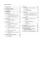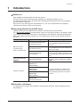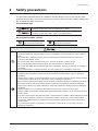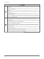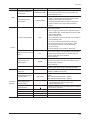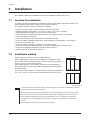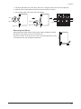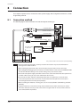
1
HM-60250 Closed Loop Stepping Motor and Driver Package AZ Series DC power input Built-in controller type OPERATING MANUAL Driver Thank you for purchasing an Oriental Motor product. This Manual describes product handling procedures and safety precautions. Please read it thoroughly to ensure safe operation. Always keep the manual where it is readily available. Table of contents 1 2 3 4 5 6 7 Introduction.......................................3 Safety precautions ...........................5 Precautions for use ..........................7 Setup guide .......................................8 CE Marking ......................................10 Preparation......................................11 6.1 6.2 Checking the product .......................... 11 How to identify the product model ....... 11 6.3 6.4 Combinations of motors and drivers ... 12 Names and functions of parts ............. 12 10.3 Transmission rate ................................ 29 10.4 Termination resistor ............................. 29 11 Guidance .........................................30 11.1 Guidance for home position setting..... 30 11.2 Guidance for position operation .......... 32 11.3 Guidance for high-speed return-to-home operation ............................................. 34 12 Operation.........................................36 12.1 Set the home position using the MEXE02 .............................................. 36 Location for installation ....................... 14 Installation method .............................. 14 12.2 Positioning operation........................... 37 12.3 High-speed return-to-home operation ............................................. 38 Connection ......................................16 8.1 8.2 Connection method ............................. 16 Connecting the power supply and 8.3 8.4 grounding ............................................ 17 Connecting the I/O signals .................. 18 Connection diagram ............................ 19 8.5 8.6 8.7 8.8 9 10.1 Address number (slave address) ........ 28 10.2 Protocol ............................................... 29 Installation.......................................14 7.1 7.2 8 10 Setting .............................................28 Connecting the RS-485 communication cable.................................................... 21 Connecting the USB cable .................. 21 Noise measures .................................. 22 Installing and wiring in compliance with EMC Directive ..................................... 23 Explanation of I/O signals..............25 9.1 9.2 Input signals ........................................ 25 Output signals ..................................... 26 12.4 JOG operation ..................................... 39 13 14 15 16 Inspection........................................41 Alarm (protective function)............42 Troubleshooting .............................43 To use the product in more convenient manners.......................45 17 Accessories (sold separately) .......46 Introduction 1 Introduction Before use Only qualified personnel should work with the product. Use the product correctly after thoroughly reading the "2 Safety precautions" on p.5. The product described in this manual has been designed and manufactured to be incorporated in general industrial equipment. Do not use for any other purpose. Oriental Motor Co., Ltd. is not responsible for any damage caused through failure to observe this warning. Operating Manuals for the AZ Series Operating manuals for the AZ Series FLEX Built-in controller type are listed below. The "OPERATING MANUAL Function Edition" does not come with the product. For details, contact your nearest Oriental Motor sales office or download from Oriental Motor website download page. After reading these manuals, keep them in a convenient place so that you can reference them at any time. Applicable product Type of operating manual OPERATING MANUAL Motor (Supplied with motor) AZ Series FLEX DC power input Built-in controller type OPERATING MANUAL Driver (Supplied with driver) OPERATING MANUAL Function Edition Data setting software MEXE02 OPERATING MANUAL Network converter CC-Link compatible NETC01-CC USER MANUAL MECHATROLINK-Ⅱ compatible NETC01-M2 USER MANUAL MECHATROLINK-Ⅲ compatible NETC01-M3 USER MANUAL EtherCAT compatible NETC01-ECT OPERATING MANUAL Description of operating manual This manual explains the functions as well as the installation method and others for the motor. This manual explains the functions as well as the installation/connection method and others for the driver. This manual explains the details of functions and data setting methods as well as the operating method and others for the driver. This manual explains how to set data using the accessory data setting software MEXE02. This manual explains the functions and installation/connection method as well as the operating method for the network converter. Hazardous substances The products do not contain the substances exceeding the restriction values of RoHS Directive (2011/65/EU). −3− Introduction General specifications Degree of protection Operation environment Storage environment Shipping environment Insulation resistance −4− IP10 Ambient temperature 0 to +50 °C (+32 to +122 °F) (non-freezing) Humidity 85% or less (non-condensing) Altitude Up to 1000 m (3300 ft.) above sea level Surrounding atmosphere No corrosive gas, dust, water or oil Ambient temperature −25 to +70 °C (−13 to +158 °F) (non-freezing) Humidity 85% or less (non-condensing) Altitude Up to 3000 m (10000 ft.) above sea level Surrounding atmosphere No corrosive gas, dust, water or oil 100 M or more when 500 VDC megger is applied between the following places: PE terminal - Power supply terminals Safety precautions 2 Safety precautions The precautions described below are intended to prevent danger or injury to the user and other personnel through safe, correct use of the product. Use the product only after carefully reading and fully understanding these instructions. Description of signs Handling the product without observing the instructions that accompany a "Warning" symbol may result in serious injury or death. Handling the product without observing the instructions that accompany a “Caution” symbol may result in injury or property damage. Description of graphic symbols Indicates "prohibited" actions that must not be performed. Indicates "compulsory" actions that must be performed. Do not use the product in explosive or corrosive environments, in the presence of flammable gases, locations subjected to splashing water, or near combustibles. This may cause fire, electric shock or injury. Do not transport, install the product, perform connections or inspections when the power is on. This may cause electric shock. Do not touch the driver while the power is on. This may cause fire or electric shock. Do not forcibly bend, pull or pinch the cable. This may cause fire or electric shock. Do not turn the FREE input to ON while the motor is operating. This may cause injury or damage to equipment. Do not disassemble or modify the product. This may cause injury or damage to equipment. Assign qualified personnel the task of installing, wiring, operating/controlling, inspecting and troubleshooting the product. Failure to do so my result in fire, electric shock, injury or damage to equipment. If this product is used in a vertical application, be sure to provide a measure for the position retention of moving parts. Failure to do so may result in injury or damage to equipment. When the driver generates an alarm (any of the driver's protective functions is triggered), first remove the cause and then clear the protective function. Continuing the operation without removing the cause of the problem may cause malfunction of the motor and driver, leading to injury or damage to equipment. Install the product in an enclosure. Failure to do so may result in electric shock or injury. Keep the driver’s input-power voltage within the specified range. Failure to do so may result in fire or electric shock. The motor and driver are designed with Class I equipment basic insulation. When installing the motor, do not touch the product or be sure to ground them. Failure to do so may result in electric shock. Connect the cables securely according to the wiring diagram. Failure to do so may result in fire or electric shock. Turn off the driver power in the event of a power failure. Failure to do so may result in injury or damage to equipment. −5− Safety precautions Do not use the product beyond its specifications. This may cause electric shock, injury or damage to equipment. Keep your fingers and objects out of the openings in the product. Failure to do so may result in fire, electric shock or injury. Do not touch the product during operation or immediately after stopping. This may cause a skin burn(s). Keep the area around the product free of combustible materials. Failure to do so may result in fire or a skin burn(s). Leave nothing around the product that would obstruct ventilation. Failure to do so may result in damage to equipment. Do not forcibly bend or pull the cable that was connected to the driver. Doing so may cause damage. Do not touch the terminals while conducting the insulation resistance test or dielectric strength test. This may cause electric shock. Use a motor and driver only in the specified combination. Failure to do so may result in fire. Use only an insulated screwdriver to adjust the driver's switches. Failure to do so may result in electric shock. For the power supply, use a DC power supply with reinforced insulation on its primary and secondary sides. Failure to do so may result in electric shock. Before supplying power to the driver, turn all input signals to the driver to OFF. Failure to do so may result in injury or damage to equipment. Provide an emergency stop device or emergency stop circuit external to the equipment so that the entire equipment will operate safely in the event of a system failure or malfunction. Failure to do so may result in injury. Before moving the motor directly with the hands, confirm that the FREE input turns ON. Failure to do so may result in injury. When an abnormal condition has occurred, immediately stop operation and turn off the driver power. Failure to do so may result in fire, electric shock or injury. To dispose of the product, disassemble it into parts and components as much as possible and dispose of individual parts/components as industrial waste. −6− Precautions for use 3 Precautions for use This section covers limitations and requirements the user should consider when using the product. Always use the cable (supplied or accessory) to connect the motor and driver. Be sure to use the cable (supplied or accessory) to connect the motor and driver. In the following condition, an appropriate accessory cable must be purchased separately. If a flexible cable is to be used. If a cable of 3 m (9.8 ft.) or longer is to be used. If a motor and driver package without a cable was purchased. Conduct the insulation resistance test or dielectric strength test separately on the motor and the driver. Conducting the insulation resistance test or dielectric strength test with the motor and driver connected may result in damage to the product. Saving data to the non-volatile memory Do not turn off the power supply while writing the data to the non-volatile memory, and also do not turn off for 5 seconds after the completion of writing the data. Doing so may abort writing the data and cause an EEPROM error alarm to generate. The non-volatile memory can be rewritten approximately 100,000 times. Note on connecting a power supply whose positive terminal is grounded The USB communication connector, CN4 connector and CN6/CN7 connectros are not insulated. When grounding the positive terminal of the power supply, do not connect any equipment (PC, etc.) whose negative terminal is grounded. Doing so may cause the driver and this equipment to short, damaging both. When connecting, do not ground equipment. −7− Setup guide 4 Setup guide Wiring guide RS-485 communication cable controller p.21 Cable for encoder Cable for motor * Required Cable for electromagnetic brake * Required 24 VDC power supply I/O cable p.18 Black White MEXE02 (PC) Power supply p.17 ÐÅ p.21 Gray colored cables are accessories (sold separately). CN4 pin assignment (p.18) Pin No. 1 2 3 4 5 6 7 8 9 10 11 12 Signal name IN0 IN2 IN4 IN6 IN-COM [0-7] IN8 Description * Control input 0 (START) Control input 2 (M1) Control input 4 (ZHOME) Control input 6 (STOP) 1 IN0 to IN7 input common Control input 8 (FW-JOG) Control output 0 OUT0 (HOME-END) Control output 2 OUT2 (PLS-RDY) 12 OUT4 Control output 4 (MOVE) OUT-COM Output common ASG+ A-phase pulse output+ BSG+ B-phase pulse output+ * ( ): Initial value −8− CN4 Pin No. 13 14 15 13 16 18 Signal name IN1 IN3 IN5 IN7 IN-COM [8-9] IN9 19 OUT1 Control output 1 (IN-POS) 20 OUT3 Control output 3 (READY) 21 22 23 24 OUT5 GND ASG− BSG− Control output 5 (ALM-B) Ground A-phase pulse output− B-phase pulse output− 17 24 Description * Control input 1 (M0) Control input 3 (M2) Control input 5 (FREE) Control input 7 (ALM-RST) IN8, IN9 input common Control input 9 (RV-JOG) * ( ): Initial value Setup guide Setting of switches Ôïð Connecting to a touch screen makes a PC unnecessary! Data editing, monitor, or checking alarm records can be performed. Function setting switch (SW1)* No.3, No.4: Sets the termination resistor. p.29 No.2: Sets the protocol. p.29 No.1: Sets the address number (slave address). p.28 p.28 Transmission rate setting switch (BAUD) * p.29 Address number setting switch (ID)* * These are switches for communication. When controlling via Modbus communication or industrial network, it is required to change the setting. Factory setting of switches Address number 0 (ID: 0, SW1-No.1: OFF) Transmission Network converter rate (BAUD: 7) Protocol Connecting with network converter (SW1-No.2: OFF) Termination Termination resistor disabled resistor (SW1-No.3, No.4: OFF) HOME-PRESET switch p.30 The home position can be set easily by pressing and holding the switch. Provide the data setting software MEXE02 and USB cable (commercially available) The MEXE02 is used for teaching function and others in addition to setting of data and parameters. Monitor function is also enhanced. Use it to check when designing or developing equipment. Teaching/remote operation window Waveform monitor window −9− CE Marking 5 CE Marking This product is affixed the CE Marking under the Low Voltage Directive and EMC Directive. Low Voltage Directive Because the input power supply voltage of this product is 24 VDC/48 VDC, it is not subject to the Low Voltage Directive but install and connect this product as follows. This product is designed and manufactured to be installed within another device. Install the product in an enclosure. For the driver power supply, use a DC power supply with reinforced insulation on its primary and secondary sides. EMC Directive This product has received EMC compliance under the conditions specified in "Example of motor and driver installation and wiring" on p.24.The conformance of your mechanical equipment to the EMC Directive will vary depending on such factors as the control system equipment used with this product, configuration of electrical parts, wiring and layout. It therefore must be verified through conducting EMC measures in a state that all parts including this product have been installed in the equipment. Applicable Standards EMI EMS −10− EN 55011 Group1 Class A EN 61000-6-4 EN 61000-6-2 Preparation 6 Preparation This chapter explains the items you should check, as well as the name and function of each part. 6.1 Checking the product Verify that the items listed below are included. Report any missing or damaged items to the branch or sales office from which you purchased the product. 6.2 Driver..................................................... 1 unit CN1 connector (5 pins) ......................... 1 pc. CN4 connector (24 pins) ....................... 1 pc. OPERATING MANUAL Driver ............... 1 copy (this document) How to identify the product model AZ 6 6 A K D - HP 15 F - 1 Number : Length (m) of a supplied connection cable Blank : Without a connection cable Blank : Shaft output type F : Flange output type (HPG geared type only) Gear ratio TS : TS geared type PS : PS geared type HP : HPG geared type HS : Harmonic geared type Blank : Standard type Power supply input K : 24 VDC/48 VDC Motor type A : Single shaft M : With electromagnetic brake Motor length Motor frame size 4 : 42 mm (1.65 in.) [40 mm (1.57 in.) for HPG geared type] 6 : 60 mm (2.36 in.) −11− Preparation 6.3 Combinations of motors and drivers Verify the model number of the purchased product against the number shown on the package label. Check the model number of the motor and driver against the number shown on the nameplate. in the model names indicates a number representing the gear ratio. When a connection cable is included, in the model names indicates a number (-1, -2, -3) representing the cable length. Type Standard TS geared PS geared HPG geared Harmonic geared 6.4 Model AZ46AKD AZ66AKD AZ69AKD AZ46MKD AZ66MKD AZ69MKD AZ46AKD-TS AZ66AKD-TS AZ46AKD-PS AZ66AKD-PS AZ46AKD-HP AZ46AKD-HPF AZ66AKD-HP AZ66AKD-HPF AZ46AKD-HS AZ66AKD-HS Motor model AZM46AK AZM66AK AZM69AK AZM46MK AZM66MK AZM69MK AZM46AK-TS AZM66AK-TS AZM46AK-PS AZM66AK-PS AZM46AK-HP AZM46AK-HPF AZM66AK-HP AZM66AK-HPF AZM46AK-HS AZM66AK-HS Driver model AZD-KD Names and functions of parts CN6/CN7 connector POWER/ALARM LED (Green/Red) C-DAT/C-ERR LED (Green/Red) CN3 connector Function setting switch (SW1) Address number setting switch (ID) Transmission rate setting switch (BAUD) USB communication connector CN2 connector HOME PRESET switch CN1 connector CN4 connector Electromagnetic brake terminals (MB1, MB2) Power supply input terminals (+, -) Protective Earth Terminal DIN lever −12− Preparation Type Name POWER/ALARM LED (Green/Red) Display POWER/ALARM LED C-DAT/C-ERR LED (Green/Red) C-DAT/C-ERR Function setting switch SW1 Address number setting switch ID Switch Transmission rate setting switch HOME PRESET switch USB communication connector Electromagnetic brake terminals (CN1) Connector, Terminal Power supply input terminals (CN1) Protective Earth Terminal (CN1) CN2 connector CN3 connector CN4 connector CN6/CN7 connector BAUD HOME PRESET − MB1, MB2 +, − CN2 CN3 CN4 CN6, CN7 Description This LED is lit in green while the power is input. If an alarm (protective function) generates, the LED will blink in red. This LED will blink or illuminate in green when the driver is communicating with the master station properly via RS-485 communication. This LED will illuminate in red when a RS-485 communication error occurs with the master station. Use this switch when controlling the system via RS485 communication. No.1: Using this switch and the address number setting switch (ID), set the address number of RS485 communication. Factory setting: OFF No.2: Sets the protocol of RS-485 communication. Factory setting: OFF No.3, No.4: Use this switch when controlling the system via RS-485 communication. Sets the termination resistor (120 ) of RS-485 communication. Factory setting: No.3 and No.4: Both OFF Use this switch when controlling the system via RS485 communication. Use this switch and SW1-No.1 of the function setting switch, to set the address number of RS-485 communication. Factory setting: 0 Use this switch when controlling the system via RS485 communication. Sets the transmission rate of RS-485 communication. Factory setting: 7 This switch is used to set the starting position (home position) when performing positioning operation. Connects a PC in which the MEXE02 has been installed. (USB2.0 mini-B port) Connects the lead wires from the electromagnetic brake. MB1: Electromagnetic brake − (Black) MB2: Electromagnetic brake + (White) Connects the power supply. +: +24 VDC/48 VDC power supply input −: Power supply ground Used for grounding via a grounding cable of AWG18 to 16 (0.75 to 1.25 mm2). Connects the motor. Connects the ABZO sensor. Connects the I/O signals. Connects the RS-485 communication cable. −13− Installation 7 Installation This chapter explains the installation location and installation method of the driver. 7.1 Location for installation The driver has been designed and manufactured to be incorporated in equipment. Install it in a well-ventilated location that provides easy access for inspection. The location must also satisfy the following conditions: 7.2 Inside an enclosure that is installed indoors (provide vent holes) Operating ambient temperature 0 to +50 °C (+32 to +122 °F) (non-freezing) Operating ambient humidity 85% or less (non-condensing) Area that is free of explosive atmosphere or toxic gas (such as sulfuric gas) or liquid Area not exposed to direct sun Area free of excessive amount of dust, iron particles or the like Area not subject to splashing water (rain, water droplets), oil (oil droplets) or other liquids Area free of excessive salt Area not subject to continuous vibration or excessive shocks Area free of excessive electromagnetic noise (from welders, power machinery, etc.) Area free of radioactive materials, magnetic fields or vacuum 1000 m (3300 ft.) or lower above sea level Installation method 35 (1.38) 100 (3.94) 50 (1.97) or more Mount the driver to a 35 mm (1.38 in.) width DIN rail. When installing two or more drivers in parallel, it is possible to install them closely in the horizontal direction. Provide a minimum clearance of 50 mm (1.97 in.) in the vertical direction. When installing three or more drivers closely, the heat generation of the inside drivers become high. Install the less frequently used drivers toward the inside. In this case, use the drivers in conditions that an ambient temperature is 0 to +40 °C (+32 to +104 °F) and the standstill current is 50% or less. Unit: [mm (in.)] Note Install the driver in an enclosure whose pollution degree is 2 or better environment, or whose degree of protection is IP54 minimum. Do not install any equipment that generates a large amount of heat or noise near the driver. Do not install the driver underneath the controller or other equipment vulnerable to heat. If the ambient temperature of the driver exceeds 50 °C (122 °F), improve the ventilation condition such as providing forced cooling by using fans or creating spaces between the drivers. Be sure to install the driver vertically (vertical position). −14− Installation 1. Pull down the DIN lever of the driver and lock it. Hang the hook at the rear to the DIN rail. 2. Hold the driver to the DIN rail, and push up the DIN lever to secure. 3. Secure both sides of the driver using end plates. Hook DIN rail DIN rail DIN lever End plate DIN lever Removing from DIN rail Pull the DIN lever down until it locks using a flat tip screwdriver, and lift the bottom of the driver to remove it from the rail. Use force of about 10 to 20 N (2.2 to 4.5 lb.) to pull the DIN lever to lock it. Excessive force may damage the DIN lever. −15− Connection 8 Connection This chapter explains how to connect the motor, power supply and I/O signals to the driver, as well as grounding method. 8.1 Connection method The following figure shows models for the electromagnetic brake type. Connect to CN3 Cable for encoder Connect to CN2 * Required Cable for motor Connect to MB1 and MB2 Black Cable for electromagnetic brake White Connect to CN4 * Required DC power supply +24 V (+48 V) 24 VDC±5% or GND 48 VDC±5% Connect to CN1 PE Gray colored cables are accessories (sold separately). Note Have the connector plugged in securely. Insecure connections may cause malfunction or damage to the motor or driver. When unplugging the motor cable, do so while pressing the latches on the connector. When plugging/unplugging the connector, turn off the power and wait for the POWER/ALARM LED to turn off before doing so. The residual voltage may cause electric shock. Do not wire the power supply cable of the driver in the same cable duct with other power lines or motor cables. Doing so may cause malfunction due to noise. The lead wires of the "cable for electromagnetic brake" have polarities, so connect them in the correct polarities. If the lead wires are connected with their polarities reversed, the electromagnetic brake will not operate properly. When installing the motor to a moving part, use an accessory flexible cable offering excellent flexibility. Keep 20 m (65.6 ft.) or less for the wiring distance between the motor and driver. To extend more than 20 m (65.6 ft.) may result in the driver heat generation or increase of the electrical noise emitted from the product. −16− Connection 8.2 Connecting the power supply and grounding Power supply connection terminals and a protective earth terminal are provided in the CN1 connector. The applicable wire size varies between lead wires for a power supply and protective earth. Be sure to use proper lead wires. Wiring the CN1 connector 2 Applicable lead wire: For power supply AWG24 to 16 (0.2 to 1.25 mm ) For grounding AWG18 to 16 (0.75 to 1.25 mm2) Length of the insulation cover which can be peeled: 7 mm (0.28 in.) 1. Strip the insulation cover of the lead wire. Screw size: M2 2. Insert each lead wire into the CN1 connector and tighten the screw. Tightening torque: 0.22 to 0.25 N·m (31 to 35 oz-in) Power supply current capacity Model Input power supply voltage AZ46 AZ66 AZ69 24 VDC±5% 48 VDC±5% Power supply current capacity 1.8 A or more 3.8 A or more 3.7 A or more How to ground Do not share the grounding wire with a welder or any other power equipment. When grounding the Protective Earth Terminal, use a round terminal and affix the grounding point near the driver. +24 VDC +48 VDC Connect to CN1 GND PE Screw size䠖M2.5 Tightening torque䠖0.4 N·m (56 oz-in) −17− Connection 8.3 Connecting the I/O signals Wiring the CN4 connector 2 Applicable lead wire: AWG24 to 16 (0.2 to 1.25 mm ) Length of the insulation cover which can be peeled: 10 mm (0.39 in.) 1. Strip the insulation cover of the lead wire. Button of the orange color 2. Insert the lead wire while pushing the button of the orange color on the CN4 connector with a screwdriver. Lead wire 3. After having inserted, release the button to secure the lead wire. Pin assignment list Pin No. 1 2 3 Signal name IN0 IN2 IN4 4 IN6 Pin No. 13 14 15 Signal name IN1 IN3 IN5 Control input 6 (STOP) 16 IN7 IN0 to IN7 input common 17 Description * Control input 0 (START) Control input 2 (M1) Control input 4 (ZHOME) 1 5 6 7 8 9 10 11 12 IN-COM [0-7] IN8 Control input 8 (FW-JOG) Control output 0 OUT0 (HOME-END) Control output 2 12 OUT2 (PLS-RDY) OUT4 Control output 4 (MOVE) OUT-COM Output common ASG+ A-phase pulse output+ BSG+ B-phase pulse output+ * ( ): Initial value −18− 13 24 Description * Control input 1 (M0) Control input 3 (M2) Control input 5 (FREE) Control input 7 (ALM-RST) 18 IN-COM [8-9] IN9 Control input 9 (RV-JOG) 19 OUT1 Control output 1 (IN-POS) 20 OUT3 Control output 3 (READY) 21 22 23 24 OUT5 GND ASG− BSG− Control output 5 (ALM-B) Ground A-phase pulse output− B-phase pulse output− IN8, IN9 input common * ( ): Initial value Connection 8.4 Connection diagram Connecting to a current sink output circuit Controller Driver IN0 4.7 kΩ 2.2 kΩ 4.7 kΩ 2.2 kΩ 4.7 kΩ 2.2 kΩ 4.7 kΩ 2.2 kΩ 4.7 kΩ 2.2 kΩ 4.7 kΩ 2.2 kΩ 4.7 kΩ 2.2 kΩ 4.7 kΩ 2.2 kΩ 4.7 kΩ 2.2 kΩ 4.7 kΩ 2.2 kΩ IN1 IN2 IN3 IN4 IN5 IN6 IN7 24 VDC IN-COM [0-7] 0V IN8 IN9 24 VDC 0V IN-COM [8-9] 12 to 24 VDC R0 10 mA or less OUT0 R0 OUT1 R0 OUT2 R0 OUT3 R0 OUT4 R0 OUT5 Output saturated voltage 3 V max. OUT-COM 0V ASG+ ASGBSG+ 26C31 or equivalent BSGGND 0V Note 0V Use input signals at 24 VDC. Use output signals at 12 to 24 VDC, 10 mA or less. If the current exceeds 10 mA, connect an external resistor R0 so that the current becomes 10 mA or less. The saturated voltage of the output signal is 3 VDC maximum. −19− Connection Connecting to a current source output circuit Controller Driver 24 VDC IN0 4.7 kΩ 2.2 kΩ 4.7 kΩ 2.2 kΩ 4.7 kΩ 2.2 kΩ 4.7 kΩ 2.2 kΩ 4.7 kΩ 2.2 kΩ 4.7 kΩ 2.2 kΩ 4.7 kΩ 2.2 kΩ 4.7 kΩ 2.2 kΩ 4.7 kΩ 2.2 kΩ 4.7 kΩ 2.2 kΩ IN1 IN2 IN3 IN4 IN5 IN6 IN7 IN-COM [0-7] 0V 24 VDC IN8 IN9 IN-COM [8-9] 0V 12 to 24 VDC R0 10 mA or less OUT0 R0 OUT1 R0 OUT2 R0 OUT3 R0 OUT4 R0 OUT5 0V Output saturated voltage 3 V max. OUT-COM ASG+ ASGBSG+ 26C31 or equivalent BSGGND 0V Note 0V Use input signals at 24 VDC. Use output signals at 12 to 24 VDC, 10 mA or less. If the current exceeds 10 mA, connect an external resistor R0 so that the current becomes 10 mA or less. The saturated voltage of the output signal is 3 VDC maximum. −20− Connection 8.5 Connecting the RS-485 communication cable Drivers can be linked. Connect this cable if you want to control your product via RS-485 communication. Connect the RS-485 communication cable to CN6 or CN7 on the driver. You can use the vacant connectors to connect a different driver. A driver link cable is available as an accessory (sold separately). A commercially-available LAN cable (shielded straight cable) can also be used to link drivers. CN6/CN7 connector Pin assignment list Pin No. 1 2 3 4 5 6 7 8 Signal name N.C. GND TR+ N.C. N.C. TR− N.C. N.C. Description Not used GND RS-485 communication signal (+) Not used 1 • • • • • 8 RS-485 communication signal (−) Not used Internal input circuit 2 GND 3 TR+ 6 TR5V SW1 No.4 2 GND 3 TR+ 1 kΩ 120 Ω 6 TR- SW1 No.3 1 kΩ 0V 0V 8.6 Connecting the USB cable Connect the USB cable that is satisfied the following specification to the USB communication connector. Specification Cable Note USB2.0 (Full Speed) Length: 3 m (9.8 ft.) or less Type: A−mini-B Connect the driver and PC directly using the USB cable. In large electrically noisy environments, use the USB cable with a ferrite core or install a ferrite core to the USB cable. −21− Connection 8.7 Noise measures The electrical noise is of two types: One is a noise to invade into the driver from the outside and cause the driver malfunction, and the other is a noise to emit from the driver and cause peripheral equipments malfunction. For the noise that is invaded from the outside, take measures to prevent the driver malfunction. It is needed to take adequate measures because signal lines are very likely to be affected by the noise. For the noise that is emitted from the driver, take measures to suppress it. Measures against electrical noise There are the following three methods mainly to take measures against the electrical noise. Noise suppression When relays or electromagnetic switches are used together with the system, use noise filters and CR circuits to suppress surges generated by them. Use an accessory cable (sold separately) when extending a wiring distance between the motor and driver. This is effective in suppressing the electrical noise emitted from the motor. Cover the driver by a metal plate such as aluminum. This is effective in shielding the electrical noise emitted from the driver. Prevention of noise propagation Connect a noise filter on the input side of the DC power supply. Place the power lines, such as the motor and power supply cables, keeping a distance of 200 mm (7.87 in.) or more from the signal lines, and also do not bundle them or wire them in parallel. If the power cables and signal cables have to cross, cross them at a right angle. 2 Use shielded cables of AWG24 to 16 (0.2 to 1.25 mm ) for power lines and signal lines. Keep cables as short as possible without coiling and bundling extra lengths. To ground a shielded cable, use a metal cable clamp that will maintain contact with the entire circumference of the cable. Ground the cable clamp near the product. Shielded cable Cable cramp When grounding PE terminals of multiple drivers to a grounding point, it becomes more effective to block the electrical noise since impedance on the grounding point is decreased. However, ground them so that a potential difference does not occur among the grounding points. An accessory driver cable including with a ground wire is available (sold separately). Refer to p.46 for details. Suppression of effect by noise propagation Loop the noise propagated cable around a ferrite core. Doing so will prevent the propagated noise invades into the driver or emits from the driver. The frequency band in which an effect by the ferrite core can be seen is generally 1 MHz or more. Check the frequency characteristics of the ferrite core used. To increase the effect of noise attenuation by the ferrite core, loop the cable a lot. Noise suppression parts Noise filter Connect a noise filter (or equivalent) in the table below on the input side of the DC power supply. When a power supply transformer is used, be sure to connect a noise filter on the AC input side of the power supply transformer. Doing so will prevent the propagated noise through the power line. Install the noise filter as close to the input terminals of DC power supply as possible. Manufacture SOSHIN ELECTRIC CO.,LTD Schaffner EMC Model HF2010A-UPF FN2070-10-06 2 Use the AWG18 (0.75 mm ) or thicker wire for the input and output cables of the noise filter, and secure firmly using a cable clamp etc. so that the cable does not come off the enclosure. −22− Connection Place the input cable as far apart as possible from the output cable, and do not wire the cables in parallel. If the input and output cable are placed at a close distance or if they are wired in parallel, the noise in the enclosure affects the power cable through stray capacitance, and the noise suppressing effect will reduce. Connect the ground terminal of the noise filter to the grounding point, using as thick and short a wire as possible. When connecting a noise filter in an enclosure, wire the input cable of the noise filter as short as possible. Wiring in long distance may reduce the noise suppressing effect. •㻌Recommended wiring example • Wiring example where the noise tends to generate Enclosure Enclosure Driver Driver Noise generated Noise filter DC power supply Noise filter DC power supply Input cable Noise suppression parts (accessories) Accessories are sold separately. Refer to p.46 for details. Driver cable This cable is a shielded cable for good noise immunity to connect the driver and controller. The ground wires useful to grounding are provided at both ends of the cable. The EMC measures are conducted using the Oriental Motor driver cable. Surge suppressor This product is effective to suppress the surge which occurs in a relay contact part. Connect it when using a relay or electromagnetic switch. CR circuit for surge suppression and CR circuit module are provided. 8.8 Installing and wiring in compliance with EMC Directive Effective measures must be taken against the EMI that the motor and driver may give to adjacent control-system equipment, as well as the EMS of the motor and driver itself, in order to prevent a serious functional impediment in the machinery. The use of the following installation and wiring methods will enable the motor and driver to be compliant with the EMC directive. Refer to p.10 for the applicable standards. Oriental Motor conducts EMC measurements on its motors and drivers in accordance with "Example of motor and driver installation and wiring" on p.24. The user is responsible for ensuring the machine's compliance with the EMC Directive, based on the installation and wiring explained below. Connecting the noise filter In large electrically noisy environments, connect a noise filter. Refer to "Noise filter" on p.22. Connecting the power supply Use a DC power supply compliant with the EMC Directive. Use a shielded cable for the wiring , and keep it as short as possible. Refer to "Prevention of noise propagation" on p.22 for grounding the shielded cable. −23− Connection Connecting the motor cable Use an accessory motor cable (sold separately) when extending the wiring distance between the motor and driver. Connecting the signal cable Refer to "Prevention of noise propagation" on p.22. How to ground The cable used to ground the motor, driver and noise filter must be as thick and short as possible so that no potential difference is generated. Choose a large, thick and uniformly conductive surface for the grounding point. Be sure to ground the Protective Earth Terminal of the motor and driver. Refer to p.17 for grounding method. Example of motor and driver installation and wiring RS-485 communication cable Controller Driver Cable for encoder FG Cable for motor FG Signal cable (Driver cable) Cable for electromagnetic brake FG AC Noise filter DC power supply Shielded cable Cable cramp PE PE FG FG Grounded panel FG Motor is a shield box. Gray colored cables are accessories (sold separately). Precautions about static electricity Static electricity may cause the driver to malfunction or suffer damage. While the driver is receiving power, handle the driver with care and do not come near or touch the driver. Always use an insulated screwdriver to adjust the driver's switches. Note −24− The driver uses parts that are sensitive to electrostatic charge. Before touching the driver, turn off the power to prevent electrostatic charge from generating. If an electrostatic charge is impressed on the driver, the driver may be damaged. Explanation of I/O signals 9 9.1 Explanation of I/O signals Input signals The following input signals of the driver are photocoupler inputs. The signal state represents the "ON: Carrying current" or "OFF: Not carrying current" state of the internal photocoupler rather than the voltage level of the signal. START input This signal starts the positioning operation. Select the operation data number and turn the START input to ON to start positioning operation. M0, M1, M2 input Select a desired operation data number based on a combination of ON/OFF status of the M0 to M2 inputs. Operation data No. 0 1 2 3 4 5 6 7 M2 OFF OFF OFF OFF ON ON ON ON M1 OFF OFF ON ON OFF OFF ON ON M0 OFF ON OFF ON OFF ON OFF ON ZHOME input When the ZHOME input is turned ON, the motor will move to the home position set by the HOME PRESET switch. Since it does not require sensors, return-to-home is possible at high-speed. FREE input When the FREE input is turned ON, the motor current will be cut off. When an electromagnetic brake motor is used, the electromagnetic brake will be released. The motor output shaft can be rotated manually since the motor holding torque is lost. Note Do not turn the FREE input ON when driving a vertical load. Since the motor loses its holding torque, the load may drop. STOP input When the STOP input is turned ON, the motor will stop. When resuming the operation, input the operation start signal to the driver after turning the STOP input OFF. ALM-RST input If the ALM-RST input is turned from OFF to ON while an alarm is generated, the alarm will be reset (The alarm will be reset at the ON edge of the ALM-RST input). Before resetting an alarm, turning the pulse input OFF, and then remove the cause of the alarm and ensure safety. Note that some alarms cannot be reset with the ALM-RST input. −25− Explanation of I/O signals FW-JOG input, RV-JOG input These signals are used to start JOG operation. The motor continuously operates in the forward direction when turning the FW-JOG input ON, and the motor continuously operates in the reverse direction when turning the RV-JOG input ON. If the signal having inputted is turned OFF, the motor will stop. If the FWD-JOG and RVS-JOG inputs are turned ON simultaneously, the motor will stop. 9.2 Output signals The driver outputs signals in the photocoupler/open-collector output mode or line driver output mode. The signal state represents the "ON: Carrying current" or "OFF: Not carrying current" state of the internal photocoupler rather than the voltage level of the signal. HOME-END output When the home position is set or when high-speed return-to-home operation is complete, the HOME-END output turns ON. IN-POS output When the motor has completed its movement, the IN-POS output will turn ON. When the motor detection position is in a range of the "(IN-POS)Positioning completion signal range" parameter (initial value: 1.8°) as a center of the command position, the IN-POS output turns ON. Command position IN-POS output ON OFF Motor position (IN-POS)Positioning completion signal range PLS-RDY output This output signal is not used for the built-in controller type driver. READY output When the driver is ready to execute operation, the READY output turns ON. Input the operation start signal to the driver after the READY output has turned ON. MOVE output The MOVE output turns ON while the motor is operating. ALM-B output When an alarm generates, the ALM-B output will turn OFF, and the motor will stop. At the same time, the POWER/ALARM LED on the driver will blink in red. The ALM-B output is normally closed. −26− Explanation of I/O signals ASG output, BSG output The ASG output and BSG output are signals output from the ABZO sensor. The ASG output is used to output pulses according to motor operation. The motor position can be monitored by counting the ASG output pulses. The number of output pulses per motor revolution varies depending on the resolution effective when turning the power on. The BSG output has a 90° phase difference with respect to the ASG output. The motor rotation direction can be determined by detecting the BSG output level at the rise of the ASG output. CW rotation ASG output CCW rotation ON OFF 90° BSG output Note ON OFF The ASG output and BSG output are subject to a maximum delay of 0.1 ms with respect to motor operation. Use these outputs to check the position at which the motor is stopped. Connect a termination resistor of 100 or more between the driver and the input of the line receiver. −27− Setting 10 Setting This chapter explains how to set the motor and driver functions. Function setting switch (SW1) No.3, No.4: Sets the Termination resistor. No.2: Sets the protocol. SW1 No.1: Sets the address number (slave address). Address number setting switch (ID) →ON Transmission rate setting switch (BAUD) Note Be sure to turn off the driver power before setting the function setting switch (SW1). The new setting of the SW1 will become effective after the power is cycled. 10.1 Address number (slave address) Set the address number (slave address) using the address number setting switch (ID) and SW1No.1 of the function setting switch. Make sure each address number (slave address) you set for each driver is unique. Factory setting ID 0 1 2 3 4 5 6 7 8 9 A B C D E F SW1-No.1 OFF ID: 0, SW1-No.1: OFF Address number (slave address) 0* 1 2 3 4 5 6 7 8 9 10 11 12 13 14 15 ID SW1-No.1 0 1 2 3 4 5 6 7 8 9 A B C D E F ON Address number (slave address) 16 17 18 19 20 21 22 23 24 25 26 27 28 29 30 31 * In the case of Modbus protocol, the address number (slave address) 0 is reserved for broadcasting, so do not use this address. −28− Setting 10.2 Protocol Set the protocol of RS-485 communication using the SW1-No.2 of the function setting switch. Factory setting OFF SW1-No.2 Protocol ON Modbus RTU mode OFF Connecting with network converter 10.3 Transmission rate Set the transmission rate using transmission rate setting switch (BAUD). The transmission rate to be set should be the same as the transmission rate of the master controller. Factory setting BAUD 0 1 2 3 4 5 6 7 8 to F Note 7 Transmission rate (bps) 9600 19200 38400 57600 115,200 230,400 Not used. Network converter Not used. Do not set BAUD to positions 6 and 8 to F. 10.4 Termination resistor Set a termination resistor to the driver located farthest away (positioned at the end) from the master controller or network converter. Turn both No.3 and No.4 of the function setting switch (SW1) ON to set the termination resistor (120 ) of RS-485 communication. Factory setting SW1-No.3, No.4 Both are OFF Both are ON Note OFF for both No.3 and No.4 (termination resistor disabled) Termination resistor (120 ) Disabled Enabled If only one of the two of No.3 and No.4 is turned ON, a communication error may occur. −29− Guidance 11 Guidance If you are new to the AZ Series, read this section to understand the operating methods along with the operation flow. How to read the guidance This chapter explains the operation procedure as follows. Home position setting (p.30) * Positioning operation (p.32) High-speed return-to-home operation (p.34) * Perform the home position setting only once initially. Once the home position is set, it is no need to set afterward. Checking the factory setting The driver is explained as a state of the factory setting. Setting item Resolution Operating current Command filter time constant Home position Factory setting 1000 P/R (0.36°/step) F (Base current 100%) 1 (1 ms) Motor position at power on 11.1 Guidance for home position setting The home position has not set at the time of shipment. Before starting operation, be sure to set the home position. Perform the home position setting only once initially. Once the home position is set, the driver keeps the home information even if the power supply is shut down. STEP 1 Connect the motor, power supply and MEXE02 to the driver 1. Wire the driver by reference to the figure. 2. Move the motor to a desired home position manually. Connect to CN3 Cable for encoder Connect to CN2 PC in which the MEXE02 has been installed Cable for motor 24 VDC power supply * Required Move the motor to a desired PE home position manually. Gray colored cables are accessories (sold separately). −30− Guidance STEP 2 Turn on the power and set the home position 1. Turn on the power supply. 2. Keep pressing the HOME PRESET switch for one second. Red color and green color on the POWER/ALARM LED blinks simultaneously. (Red and green colors may overlap and it may be visible to orange.) POWER/ALARM LED HOME PRESET switch 3. Remove the hand from the HOME PRESET switch within three seconds after the POWER/ ALARM LED started blinking, and press the switch again. After both red color and green color on the POWER/ALARM LED are lit, only green color continues to be lit. The home position is set. Note For the procedure 3, be sure to perform within three seconds after the POWER/ALARM LED started blinking. If three seconds were passed, the POWER/ALARM LED will return to the state being lit in green. In this case, perform from the procedure 2 again. See the following timing charts for the procedure of home position setting. 1 sec HOME PRESET switch POWER/ALARM LED (Green) ON 2 3 3 OFF ON 1 OFF 1 sec POWER/ALARM LED (Red) HOME-END output ON OFF ON OFF −31− Guidance 11.2 Guidance for position operation This section explains an example to perform positioning operation using the MEXE02. After performing "11.1 Guidance for home position setting" on p.30, continuously perform test operation. Note STEP 1 Before operating the motor, check the condition of the surrounding area to ensure safety. Set the operation data using the MEXE02 1. Start a PC, and continuously start the MEXE02. Refer to the "Data setting software MEXE02 OPERATING MANUAL" for how to start or use the MEXE02. 2. Using the MEXE02, set the operation data of No.0 as follows. Speed 8500 [step] 500 [Hz] 1. 5 ] z/s [kH [kH z/s ] 5 1. 2000 [Hz] 1 [s] 3 [s] 1 [s] Time Setting example of MEXE02 Input in increments of 0.001 kHz/s. −32− Guidance STEP 2 Operate the motor 1. Click the [Teaching, remote operation] short-cut button in the left side of the screen. The teaching/remote operation window appears. 2. Click "Start the teaching remote operation." Since the pop-up window (Warning) is displayed, click [Yes]. 3. Write the edited data to the driver. Click "Writing all data. (PC −> Product)," and click [OK]. The contents of the data No.0 will be written to the driver. −33− Guidance 4. Click [Start positioning operation]. Since the pop-up window (Warning) is displayed, click [Yes]. The motor performs positioning operation. 11.3 Guidance for high-speed return-to-home operation After operation, return the motor to the home position. Using high-speed return-to-home operation (ZHOME) can return the motor position to the home position easily. After performing "11.2 Guidance for position operation" on p.32, continuously perform high-speed return-to-home operation. STEP 1 Check the present position 1. Check the "Actual position" in the teaching/remote operation window. 2. To check if the ABZO sensor has memorized the home position, once turn off the power, and turn on again. 3. Check the "Actual position" again. Check that the actual position is not 0. −34− Guidance STEP 2 Execute high-speed return-to-home operation 1. Click "ZHOME operation." Since the pop-up window (Warning) is displayed, click [Yes]. The motor will start high-speed return-to-home operation. 2. After the motor returns to the home position, check that the "actual position" is 0. STEP 3 End the teaching/remote operation To end the teaching/remote operation, unselect "Start the teaching remote operation." −35− Operation 12 Operation Three types of operation signals are assigned to the CN4 connector at the time of shipment. This chapter explains operations (positioning operation, JOG operation, and high-speed return-tohome operation) that can be performed in the factory setting only. 12.1 Set the home position using the MEXE02 The home position can be set using the MEXE02 other than the HOME PRESET switch of the driver. 1. Click the [Teaching, remote operation] short-cut button int the left side of the screen. The teaching/remote operation window appears. 2. Click the "Teaching, remote operation," and click [Yes] on the pop-up window (Warning). 3. Adjust the motor position using the JOG operation switches. −36− Operation 4. When adjusting the motor position manually, click [FREE: ON] first, and click [Yes] on the popup window (Warning). The holding power of the motor output shaft is lost, and the output shaft can be turned by hand. After adjustment, click [FREE: OFF], and recover the motor excitation. 5. After setting the motor home position, click [Position Preset], and click [Yes] on the pop-up window (Warning). The home position is set and written to the driver. 12.2 Positioning operation Set the operation data and performe positioning operation. 1. Turn on the power supply. The READY output and PLS-RDY output turn ON. 2. Check the READY output is turned ON and turn the START input ON by selecting the operation data number with the M0 to M2 outputs. The motor will start positioning operation. 3. Check the READY output has been turned OFF and turn the START input OFF. When the operation is complete, the READY output will turn ON. Power supply M0 to M2 input START input READY output PLS-RDY output IN-POS output ON 1 OFF ON 2 OFF ON 2 3 OFF ON OFF 3 ON OFF ON OFF Motor operation Refer to the OPERATING MANUAL Function Edition for details about operation. −37− Operation 12.3 High-speed return-to-home operation High-speed return-to-home operation is used to return to the home position that is set by the HOME PRESET switch. 1. Turn on the power supply. The READY output and PLS-RDY output turn ON. 2. Check the READY output has been turned ON and turn the ZHOME input ON. The READY output turns OFF, and the motor will start high-speed return-to-home operation. 3. If the READY output has been turned OFF, the ZHOME input may be turned OFF. When the home position is detected, the operation will be stopped. The HOME-END output and READY output will turn ON. Power supply ZHOME input HOME-END output READY output PLS-RDY output ON 1 OFF 2 ON 3 OFF ON OFF ON OFF 2 3 ON OFF Motor operation When changing the operating condition of high-speed return-to-home operation 1. Click on the “Paremeter,” “Motor and Mechanism(Coordinates/JOG/Home Operation),” in the left side of the screen. Motor and mechanism parameter window will appears. −38− Operation 2. The operating condition can be changed using three parameters in the figure. 3. After changing the operating condition, click the [Writing data] icon in the toolbar to download to the driver. The process has been completed. 12.4 JOG operation Constant speed operation (inching operation) can be performed with JOG operation. The motor operates continuously while the FW-JOG input or RV-JOG input is being ON. 1. Turn on the power supply. The READY output and PLS-RDY output turn ON. 2. Check the READY output has been turned ON and turn the FW-JOG input or RV-JOG input ON. The motor will start operation. When the FW-JOG input is turned ON, the motor rotates in the forward direction, and when the RV-JOG input is turned ON, the motor rotates in the reverse direction. 3. Turn the input signal OFF. The motor will decelerate to a stop. When the motor stops, the READY output will turn ON. Power supply ON 1 OFF 2 FW-JOG input or ON RV-JOG input OFF READY output PLS-RDY output IN-POS output ON 3 2 OFF ON OFF ON OFF Motor operation −39− Operation When changing the operating condition of JOG operation 1. Click on the “Paremeter,” “Motor and Mechanism(Coordinates/JOG/Home Operation),” in the left side of the screen. Motor and mechanism parameter window will appears. 2. The operating condition can be changed using five parameters in the figure. 3. After changing the operating condition, click the [Writing data] icon in the toolbar to download to the driver. The process has been completed. −40− Inspection 13 Inspection It is recommended that periodic inspections be conducted for the items listed below after each operation of the motor. If an abnormal condition is noted, discontinue any use and contact your nearest Oriental Motor sales office. During inspection Are the openings in the driver blocked? Are any of the mounting screws or connection parts of the driver loose? Is there attachment of dust, etc., on the driver? Are there any strange smells or appearances within the driver? Note The driver uses semiconductor elements, so be extremely careful when handling them. Static electricity may damage the driver. −41− Alarm (protective function) 14 Alarm (protective function) When an alarm generates, the ALM-B output will turn OFF and POWER/ALARM LED will blink in red. Before resetting an alarm, always remove the cause of the alarm and ensure safety. For details about alarms, refer to the "OPERATING MANUAL Function Edition." Example of the alarm monitor screen of the MEXE02 The alarm message can be checked using the "Alarm monitor" of the MEXE02. The measures are displayed. −42− The cause that generated the alarm is displayed. Troubleshooting 15 Troubleshooting During motor operation, the motor or driver may fail to function properly due to an improper setting or wiring. When the motor cannot be operated correctly, refer to the contents provided in this section and take appropriate action. If the problem persists, contact your nearest Oriental Motor sales office. This chapter describes problems that may occur during operation in addition to the initial settings. Refer to the OPERATING MANUAL Function Edition for these contents. Phenomenon Possible cause The motor is not The C-ON input is turned OFF. excited. The motor output shaft The FREE input is turned ON. can be moved by hand. There is holding torque even if motor excitation is Effect of dynamic brake. turned OFF. The motor does not operate. The motor rotates in the direction opposite to the specified direction. The gear output shaft rotates in the direction opposite to the motor. Motor operation is unstable. Motor vibration is too great. The electromagnetic brake does not release. An electromagnetic brake motor is used and the electromagnetic brake is in the holding state. The STOP input is turned ON. The position (distance) is not set in the operation data while positioning operation. The FWD-JOG input and RVS-JOG input are turned ON simultaneously in the JOG operation. The "motor rotation direction" parameter is set wrong. Remedial action Turn the C-ON input ON and confrm that the motor will be excited. Turn the FREE input OFF. If motor excitation is turned OFF by C-ON input or STOP input, the holding torque will be generated larger than when the power is shut off (dynamic brake). To release the dynamic brake, shut off the power or turn the FREE input ON. Check the connections between electromagnetic brake and driver. Turn the STOP input OFF. Check the operation data. Turn either FWD-JOG input or RVS-JOG input ON. Check the setting of the "motor rotation direction" parameter. With TS geared motor, the gear output shaft rotates in the direction opposite to the motor when the gear ratio is 20 or 30. A gear that rotates in the direction opposite to the motor shaft is used. With Harmonic geared motors, the gear output shaft always rotates in the direction opposite to the motor. Connection error in the motor or Check the connections between the driver, motor power supply. and power supply. Return the "Base current" parameter or "Stop current" parameter to its initial setting and check The "Base current" parameter or the motor operation. If the current is too low, the "Stop current" parameter is too low. motor torque will also be too low and operation will be unstable. Lower the current using the "Base current" Load is too small. parameter. Vibration will increase if the motor’s output torque is too large for the load. The power is not supplied to the Check the connection of the electromagnetic electromagnetic brake. brake. −43− Troubleshooting Note When an alarm generates, check the alarm message using the MEXE02 or via RS-485 communication. I/O signals can be monitored using the MEXE02 or via RS-485 communication. Use to check the wiring condition of the I/O signals. −44− To use the product in more convenient manners 16 To use the product in more convenient manners Using the MEXE02, you can set the operation data or change I/O signals that assign to the CN4 connector. Also, you can monitor the operating status or perform test operation. Refer to the OPERATING MANUAL Function Edition for details about operation. Like to set the resolution Like to change the I/O Like to utilize the based on the function assignment sequence function Like to utilize convenient Like to check operation Like to change the functions for maintenance by the waveform monitor alarm conditions −45− Accessories (sold separately) 17 Accessories (sold separately) Driver cable This cable is a shielded cable for the driver control I/O that has good noise immunity. The ground wires useful to grounding are provided at both ends of the cable. Model CC16D010B-1 CC16D020B-1 Length [m (ft.)] 1 (3.3) 2 (6.6) RS-485 communication cable You can link drivers using this cable connected to the CN6/CN7 connectors. Model: CC001-RS4 [0.1 m (0.3 ft.)] CR circuit for surge suppression This product is effective to suppress the serge which occurs in a relay contact part. Use it to protect the contacts of the relay or switch. Model: EPCR1201-2 CR circuit module This product is effective to suppress the surge which occurs in a relay contact part. Use this product to protect the contacts of the relay or switch. 4 pieces of CR circuit for surge suppression are mounted on the compact circuit, and this product can be installed to the DIN rail. This product can make the wiring easily and securely since it also supports terminal block connection. Model: VCS02 −46− −47− Unauthorized reproduction or copying of all or part of this Operating Manual is prohibited. If a new copy is required to replace an original manual that has been damaged or lost, please contact your nearest Oriental Motor branch or sales office. Oriental Motor shall not be liable whatsoever for any problems relating to industrial property rights arising from use of any information, circuit, equipment or device provided or referenced in this manual. Characteristics, specifications and dimensions are subject to change without notice. While we make every effort to offer accurate information in the manual, we welcome your input. Should you find unclear descriptions, errors or omissions, please contact the nearest office. , , and are registered trademark or trademark of Oriental Motor Co., Ltd., in Japan and other countries. Other product names and company names mentioned in this manual may be registered trademarks or trademarks of their respective companies and are hereby acknowledged. The third-party products mentioned in this manual are recommended products, and references to their names shall not be construed as any form of performance guarantee. Oriental Motor is not liable whatsoever for the performance of these third-party products. © Copyright ORIENTAL MOTOR CO., LTD. 2014 • Please contact your nearest Oriental Motor office for further information. Technical Support Tel:(800)468-3982 8:30 A.M. to 5:00 P.M., P.S.T. (M-F) 7:30 A.M. to 5:00 P.M., C.S.T. (M-F) www.orientalmotor.com Tel:+55-11-3266-6018 www.orientalmotor.com.br Headquarters Düsseldorf, Germany Technical Support Tel:00 800/22 55 66 22 www.orientalmotor.de Tel:01256-347090 www.oriental-motor.co.uk Tel:01 47 86 97 50 www.orientalmotor.fr Tel:02-93906346 www.orientalmotor.it Singapore Tel:1800-8420280 www.orientalmotor.com.sg Korea Tel:080-777-2042 www.inaom.co.kr Tel:1800-806161 www.orientalmotor.com.my Hong Kong Branch Tel:+852-2427-9800 Tel:1800-888-881 www.orientalmotor.co.th Headquarters Tokyo, Japan Tel:03-6744-0361 www.orientalmotor.co.jp Tel:+91-80-41125586 www.orientalmotor.co.in Tel:0800-060708 www.orientalmotor.com.tw Tel:400-820-6516 www.orientalmotor.com.cn