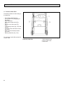
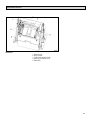
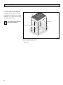
1
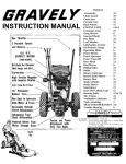
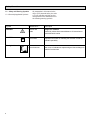
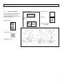
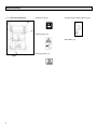
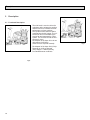
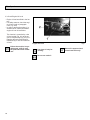
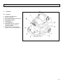
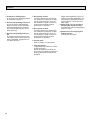
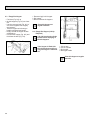
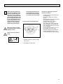
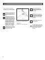
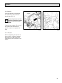
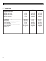
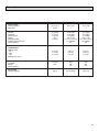
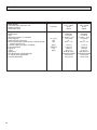
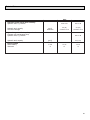
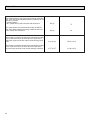
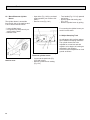
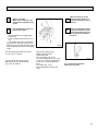
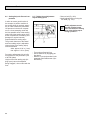
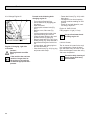
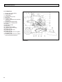
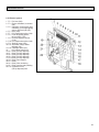
Apex 49
Model: PB40GL,PB40PL,PB40GH,PB40PH
User Manual
Introduction
Dear customer,
It is our desire that the good characteristics of the Apex 49 should
justify the confidence you demonstrated by making this purchase.
Before first operation of the machine,
Before first operation of your Apex 49,
read these instructions and safety inread these instructions carefully. The
formation carefully and comply with
manual provides valuable information
about operation, service and maintenance. them.
Please be advised explicitly that
we cannot accept any legal issues out of the contents of this
manual.
If repair work has to be performed make sure that only genuine spare parts are used; only
genuine spare parts may guarantee a dependable machine.
The symbol as used in this manual
identifies items relevant to safety.
Please observe the safety provisions (see chapter 1).
Valid as of:
2
March 2007
Proper Use
Proper Use
The Apex sweeper has been
exclusively designed for collecting
dry and moist matter from floor surfaces in e.g. factories, storage buildings, parking ground and pedestrian areas. Using the machine
beyond this scope of application
will be deemed improper use; The
manufacturer cannot be held liable
for consequential damages.
The term of proper use also includes operation, maintenance and
repair work to be performed in compliance with the manufacturer's
specifications.
The Apex 49 may be used by personnel only that are familiar with the
machine and aware of possible
hazards involved.
The applicable Accident Prevention
Regulations, Road Traffic
Regulations, and aspects of safety
and working medicine in vigour will
have to be complied with.
If modifications to the machine are
made in absence of the manufacturer's prior consent, the latter cannot be held liable for damage resulting from such unauthorized modification.
The machine has not been
designed for collecting
dusts which are detrimental
to health or explosive.
parts or accessories without prior
and explicit consent or by non-compliance with the maintenance
instructions.
Notes on warranty
Inspection
The terms of the sales contract apply.
Damages are not subject to warranty
if they are due to non-compliance
with the maintenance and service
provisions. The maintenance work
has to be performed by an authorized
service center and confirmed in the
"Maintenance certificate" which is the
warranty document.
The following is excluded from warranty:
fuses, natural wear, damages caused
by overload, inexpert handling and
unauthorised modification of the
machine. Moreover, any claim for
warranty cannot be accepted if damages at the machine are caused by fitting
Carefully unpack and inspect your Apex
49 for shipping damage. Follow
unpacking instructions on shipping
pallet. Each unit has been tested
and thoroughly inspected before
shipment. Any damage is the responsibility of the delivery carrier who
should be notified immediately.
3
Safety Information
1
1.1
Safety Information
General Safety Information
Apart from the instructions contained
in this manual, the general safety
instructions and accident prevention
regulations, as imposed by law will
have to be complied with. Do not put
the Manual aside without reading it
even if you used similar sweepers
before. Take the time to read them
now and save time later. Machines
with known defects must not be used.
It will be of essence to make yourself
familiar with all accessories and controls and their functions before you
start working. Avoid the mess of
having to read this book while trying
to run the machine.
Using the machine in areas with
explosion hazard, on public roads
and places is prohibited.
The operator has to use the machine
within its design limits.
Shut the motors down before transporting the machine.
Keep clear of hazard zone!
Before commencing work, the operator has to make sure that the SW5X
and its accessories are in proper and
safe condition.
Warning and instruction labels attached to the machine contain important information about safe operation.
Illegible or lost labels have to be
replaced.
Make sure that all covers
are fitted before starting to
sweep.
Provide for sufficient
ventilation when sweeping
indoors (dust and
combustion gas).
Pinching and shearing hazard. Provide for required
safe distance before lifting
or lowering the dirt hopper.
Shut down the engine before re-fuelling.
Smoking and handling open
flames is prohibited when
filling fuel tanks or when
working at or in the vicinity
of components containing
fuel.
5
Safety Information
1.2 Safety and Warning Symbols
1.2.1Generally Applicable Symbols
All paragraphs in this manual referring to your personal safety, the safety of your machine and the environment protection are attributed one of
the following warning symbols:
Symbol
Hazardous for....
Description
DANGER
persons and
goods
dangerous situation
caused by misuse inaccurate adherence of instructions or
prescribed work routine
the machine
important information on handling the machine in order to
maintain operability
the environment
due to use of substances representing an inherent danger to
health of environment
CAUTION
Ecological hazard
6
Safety Information
1.3
Labels at the Machine
The following safety and information
signs are legibly attached to the
machine. Missing or illegible stickers
have to be replaced.
Inflation pressure (4)
Ignition lock (6)
90 PSI
Brake (7)
Read and observe operator's
Manual (5)
Folding apron (1)
Noise power level (8)
91 dB (A)
Parking brake (2)
Nameplate front (3)
Fig.1
7
Safety Information
1.3 Labels at the Machine
Hydraulic fluid (9)
Cylinder broom wearing take-up (12)
Rotating parts (10)
Nameplate (13)
Fig. 2 Safety and information
signs
8
Burning surface (11)
Safety Information
1.3 Labels at the Machine
Pinching hazard (16)
(Lifted-Up Disposal)
High-pressure cleaner (14)
Do not clean by means of
high pressure cleaner or
vapour jet.
9
Safety Information
1.4
Operation/Safety
Information
Vacuum sweepers may be run by
qualified personnel only; such personnel will have to have evidenced
their qualification for running the
machine to the owner or his authorized representative; operators explicitly will have to be instructed by the
owner or his authorized representative to use the machine.
The machine may be used
for cleaning such surfaces
approved by the owner or
this authorised representative for operation of vacu
um sweepers.
Before starting the engine,
switch off all drives
Transporting persons on the machine
is prohibited. Ride-on machine types
are to be started with the driver being
seated.
10
Never leave the machine unattended
before the motors are off and the machine is protected against unintended
movements.
To prevent the machine from unauthorized use, pull the control key to block
all drives.
Shut down the motors before transport of the machine. The driver has to
take account of local conditions and
when operating the sweeper he has
to watch out for other persons, especially children.
Do not open hood or
fairings with the machine
running.
This machine must not be
used as dust-evacuating
machine with dust filter insert (separator) to collect
dusts which are hazardous
to health.
Compared to four-wheeled
vehicles, driving stability of
three-wheeled vehicles is
reduced. We thus recommend:
- do not negotiate curves at
high speed.
- do not turn at slopes but
on level ground only
- ride up- or downhill
straight.
Safety Information
Warning and instruction labels attached to the machine contain important information about safe operation
Provide for sufficient ventilation when sweeping indoors (dust and combustion
gas).
Proceed to filter shaking only if the dirt hopper is in closed position.
1.5
Cleaning Information
The machine is splash-proof (IPX3).
Do not clean the SW5X by
means of high pressure cleaner or vapour jet.
Proceed to cleaning of the
dirt hopper in regular intervals to preclude formation of
bacterial deposits.
11
Safety Information
1.6 Maintenance Instructions
A good approach to prevention of
accidents is proper maintenance of
the machine.
Before proceeding to repair or maintenance work remove the key.
Use appropriate tools for maintenance, service, setting etc.
As far as aspects of safety are concerned, spare parts will have to be at
least of the same quality as the genuine spare parts.
Switch off the motors before maintaining the machine
or replacing parts of it. Turn
off the machine and pull the
key.
Check hydraulic hoses and
lines for leakage or damages in regular intervals. Replace defective hoses and
lines immediately.
12
Before changing wheels
protect the machine against
rolling by placing wedges.
Proceed to wheel changing
when the machine is on level and solid ground.
Do not repair the pneumatic
tires mounted to the machine yourself. Dismount the
wheel and take it to repair to
a tire workshop.
Use of other than the cylinder brooms and side brushes approved by the manufacturer is not acceptable
(see technical data) since
use of other cylinder
brooms and side brushes
may affect your safety.
When handling lubricating agents, the applicable regulations for
protection of the environment and prevention of fire have to be
complied with. Provide
for disposal of used oil
and grease in accordance with the provisions imposed by law.
Collect cleaning
agents, oil, fuel oil, grease etc. and provide for
adequate disposal. Wipe away spilled substances.
Safety Information
Before commencing any
work on the electric system
disconnect battery (neg. lead) of the SW5X and pull the
ignition key.
Keep batteries dry and clean and clear of soiling such
as e.g. metallic dust to avoid leakage current.
Do not keep batteries dsicharged for a longer period;
always recharge them as
soon as possible.
Do not place metal objects
or tools onto batteries.
Short-circuit and deflagration hazard.
Top with distilled water only. Never refill battery acid
in battery cells of perfect
condition.
Spilled (straight) battery
acid must not get into the
sewage system before having been neutralised. Comply with the regulations imposed by law and observe
local provisions.
Battery acid is highly
caustic (keep clear of
children).
When checking the battery
acid level, wear safety glasses. If acid splashes get into the eyes rinse with clear
water for 15 minutes and
contact a doctor immediately.
Use appropriate protective
means (e.g. protective gloves or finger-stalls) when
handling battery acid.
Do not use open flames
(explosion hazard).
13
Description
2
Description
2.1 Functional Description
The side brush is used to collect dirt
at borders and to enlarge the working
width as well as to increase the area
performance on large surfaces.
The cylinder broom casts the debris
overhead into the dirt hopper. The collected fine dust is evacuated by the
suction fan and separated by a filter
system. The air returned into the environment is clean.
Dirt disposal of the Apex 49 is via two
dirt hoppers (2x30 litres)
which are to be emptied manually.
Dirt disposal of the Apex 49H (Lift-Up
Disposal) is via lift-up disposal
(lift-up height > 1350mm) directly
into standard waste containers.
Fig.3
14
Fig.4
Description
2.2 Cylinder Broom
The cylinder broom is equipped with
12 rows of bristles arranged in
V-shape.
The cylinder broom width amounts to
27.6 in. (700mm) and its diameter to
13.6 in. (345mm).
2.3 Side Brush
At the standard version, the side
brush is located at the front right of
the machine. The operator lifts and lowers it by hand lever.
The side brush has a light inclination.
The swinging area of the side brush
arm is limited by stop screws.
The side brush is driven by V-belt.
For special application, fitting of a
second side brush at the left is possible.
2.4 Filter System / Dust
Evacuation
The filter system is located in the filter case above the dirt hopper. The
suction fan transports the fine dust
raised by the cylinder broom to the
plate filter where it is separated. The
fine dusts sets at the outsides of the
filter blades.
In case of heavy dust development, check and clean
the plate filter at regular
intervals.
2.6 Steering
Steering is controlled mechanically
from steering wheel to front wheel via
chain. This chain is to be re-adjusted
as required.
2.7 Wheels
Pneumatic tyres with hose, size.
4.00 - 4 6PR
Inflation pressure: 90 PSI (6 bar)
Solid rubber tyres (Option)
2.5 Shaking System
Due to normal working vibration the
set dust partly falls off into the dirt
hoper. To ensure working in a dustfree environment, however, actuate
the shaking system regularly, or after
request by the pilot lamp at the latest.
15
Description
2.8 Brake
The Apex 49 is equipped with a service
brake. This brake has been constructed
as shoe brake and equally serves as
parking brake.
It is located in the rear wheels and is
actuated via cables.
A special adjustment screw is situated at the right-hand rear wheel.
Any work at the braking
system has to be executed
by qualified persons in a
qualified workshop only.
2.9 Traction Drive Assembly
The Apex 49 is equipped with a hydrostatic drive assembly which is driven
by the combustion engine via pump.
16
2.10 Hydraulic System
Lift-Up Disposal
The hydraulic system comprises a
compact unit (hydraulic pump with
hydraulic tank), the hydraulic hoses
and a hydraulic cylinder.
Hydraulic fluid: Mobiloil DTE 15 M
The named hydraulic fluid has been
filled in the hydraulic system in the
factory.
Filling of hydraulic tank: 0.2 gal. (0.76
litre)
First Operation
3
First Operation
The Apex49 has been extensively
tested and submitted to a functional
check before delivery.
Only qualified personnel of your local
contract dealer are allowed to proceed to first operation. After shipping
of the machine, we advise your contract dealer. He will contact you to
make a date for briefing lessons.
3.1
General
Smoking and handling open
flames is prohibited when
filling fuel tanks or when
working at or in the vicinity
of components containing
fuel.
Do not use the Apex 49 at
ambient temperatures of more
than 104°F (40°C).
Do not start the machine at
temperatures of 5°F (-15°C)
or less.
Liquid propellant gas
system: refer to LPG operating instructions.
Fuel tank
3.2 Refill Fuel
The fuel tank is located under the foldable seat hood.
Use clean fuel oil only. Store fuel in approved and closed reservoirs only.
- Turn engine off
- Secure machine by engaging the
parking brake.
- Pull ignition key.
- Fold back seat hood.
Fig.5
- Check filling level at the filling level
indicator (Fig. 5/2).
- Remove tank lid (Fig. 5/1) before
filling.
Turn engine off before filling
fuel.
Smoking and handling open
flames is prohibited when
filling fuel tanks or when
working at or in the vicinity
of components containing
fuel.
17
First Operation
3.3 Check Engine Oil Level
- Engine oil has been filled in the factory.
- For safety reasons, check the engine oil level (refer to paragraph
6.9.2, Fig. 23/2)
- In order to protect the engine, it is
switched off or cannot be started if
engine oil level is insufficient.
This function is controlled by a low
oil level switch (Fig. 0/1) at the engine. A red pilot lamp (Fig. 0/2) is situated at this switch and lights simultaneously in case of insufficient
oil level.
Engine Oil Level
Before the machine is operable again, refill oil until
the prescribed level is attained.
Use clean oil only for
refilling.
Do not use used oil.
18
Fig.0
Store oil in approved and
closed reservoirs only.
Operation
4
Operation
4.1 Controls
1
2
3
4
5
6
7
8
Actuator for folding apron
Service brake lock
Service brake/parking brake pedal
Drive pedal, reverse
Drive pedal, forward
Control panel
Seat adjustment
Safety knob, lock for release of
swinging dirt hopper function
(Lift-Up Disposal)
9 Release lever for swinging dirt
hopper function (Lift-Up Disposal)
Fig.6
19
Operation
1 Actuator for folding apron
to open and close the folding apron
for collecting coarse dirt.
2 Service brake/parking brake lock
to lock the service brake/parking
brake. If locked, the service brake
works as parking brake. Release
the lock by depressing the service
brake pedal (3).
3 Service brake/parking brake pedal
to actuate the service brake at the
rear wheels. Before leaving the machine unattended, engage the service brake and lock.
4 Drive pedal, reverse
to change direction to reverse ride
with continuous regulation of riding
speed at the same time. If the driver releases the pedal it returns to
initial position and the machine
slows down to standstill.
5 Drive pedal, forward
to change direction to forward ride
with continuous regulation of riding
speed at the same time. If the driver releases the pedal it returns to
initial position and the machine
slows down to standstill.
6 Control panel
Refer to chapter "Control panel"
7 Seat adjustment
to adjust the seat position to drivers
of different height.
Adjust the seat so as to allow the
driver being comfortably seated and
attaining all elements required for
operation.
20
- Adjust seat lengthwise: push lever
slightly to the right and displace seat forwards or backwards to the required position. Then let the lever
catch again.
8 Safety knob, lock for release of
swinging dirt hopper function
to release the lever for swinging dirt
hopper function.
9 Release lever for swinging dirt
hopper function
to swing the dirt hopper
Operation
4.2 Control Panel
1 Cylinder broom lever
2 Release of lifted-up disposal function
3 Horn
4 Suction fan/shaking system knob
5 Choke flap knob
6 Flashlight (option)
7 Lighting (option)
8 Lift and lower (Lift-Up Disposal)
9 Side brush lever
10 Pilot lamp, parking brake
11 Battery charge status indicator
12 Hourmeter
13 Pilot lamp, fan
14 Pilot lamp, shaking system
15 Engine speed regulation knob
16 Ignition switch
Fig.7
21
Operation
1 Cylinder broom lever
to lift and lower as well as to
switch on and off the cylinder
broom and the side brush.
- Lower cylinder broom as well as
switch on cylinder broom and side
brush
= push lever
- Lift cylinder broom as well as switch
off cylinder broom and side brush
= pull lever
22
2 Release for lifted-up disposal
function
to release the lifted-up disposal
function for lowering of lifting.
Has to be actuated before
pressing the key for
lifting/lowering lifted-up disposal function. Hold the key
during lifting/lowering.
Before changing lifting to
lowering or vice versa, the
"Release Lifted-Up Disposal" key has to be released
once and pressed again
3 Horn
An acoustic signal sounds upon
actuation of this button.
Operation
After jolting, the knob is to
be kept in position 1 for about 10 seconds.
Reduce engine speed to idling in order to optimize the
cleaning result in case of
heavy fine dust load.
4 Suction fan/shaking system
knob
Knob position (from bottom to top):
Pos. 0 Activated vacuuming function
(close flap before sweeping
dry surfaces or collecting
dry dirt).
Pos. 1 Deactivated vacuuming
function (open flap before
sweeping wet surfaces and
collecting wet dirt).
Pos. 2 Shaking system ON (pull
knob to stop and then
release)
If the yellow pilot lamp (Fig. 7/13)
lights, actuate the shaking system
(position 2).
In this position, the shaking system is
operable and proceeds to jolting in 7
repeated intervals.
If the engine has already attained temperature, do not
actuate the choke flap and
start with full throttle.
6 Flashlight (option)
to switch the flashlight ON/OFF.
Do not hold the knob in
position 2!
5 Choke flap knob
to actuate the choke flap (cold
start)
- Knob down - choke not actuated
- Knob pulled up - choke actuated
for cold start.
7 Lighting (option)
to switch the driving headlight
ON/OFF.
23
Operation
8 Lift and lower (lifted-up disposal)
to lift and lower the dirt hopper.
Lift the dirt hopper by pressing the
key until the desired height for lifting-out is attained.
When lowering the dirt hopper make sure to hold the key pressed
until the hopper has contact with
the frame.
9 Side brush lever
to lift and lower the side brush.
- Lower side brush
= push lever
- Lift side brush
= pull lever
12 Hourmeter
indicates the operating hours. The
counter works only if the driver is
seated and the ignition is ON.
Actuate release key for lifted-up disposal and hold
before lifting or lowering.
10 Pilot lamp, parking brake (red)
lights upon actuation of the parking brake Extinguishes upon
release of the parking brake.
24
11 Battery charge status indicator
(red)
lights upon actuation of the ignition
switch and has to extinguish as
the engine fires.
Operation
13 Pilot lamp, suction fan (orange)
lights if the suction fan is not activated.
14 Pilot lamp, shaking system (yellow)
Proceed to jolting of the filter
system upon lighting of this pilot
lamp by actuating the knob
(Fig.7/5).
15 Engine speed regulation knob
to adjust the engine speed. Service speed is attained by pulling
the knob up.
For safety reasons, the Apex
has been equipped with a seat
contact switch.
Starting the engine is possible only after the driver
has taken place on the seat.
If seat contact is interrupted
while the engine is running,
the combustion engine of
the Apex has to be re-started.
16 Ignition switch
to switch ignition on and off, to
start and stop engine and to secure it against unauthorised use.
The pilot lamp flashes during the shaking procedure
and extinguishes after filter
has been cleaned. Jolting is
effectuated in 7 intervals.
25
Operation
4.3 Empty Dirt Hopper
- Fold bow (Fig. 8/3) up
= the dirt hoppers (Fig. 8/2) are lowered.
- Use the recessed grip (Fig. 8/1) of
one of the hoppers to lift it lightly
and extract it.
- Take the hopper at its bow-type
handle to disposal and empty.
- Empty second dirt hopper as described above.
- Re-insert dirt hopper (Fig. 8/2) and
fold down the bow (Fig. 8/3).
1 Recessed grip in dirt hopper
2 Dirt hopper
3 Bow to lift/lower dirt hoppers
Clean dirt hoppers at
regular intervals.
4.4 Empty Dirt Hopper (Lift-Up
Disposal)
Lift side brush and cylinder
broom before emptying of
the dirt hoppers.
Fig.9
If the hopper is lifted with
the cylinder broom still running, the engine is switched
off.
1
2
3
4
Lift-out arm
Lift-out cylinder
Dirt hopper
Bow-type handle
Fig.8
Clean dirt hopper at regular
intervals.
26
Operation
Riding with the lifted hopper reduces stability of the
machine significantly. For
this reason, do not lift the
hopper but just before emptying. Before lifting the hopper, the operator has to make sure that no persons or
objects are behind or next
to the machine. Stop the
machine on level ground
before lifting the hopper.
Pinching and shearing hazard. Provide for required
safe distance before lifting
or lowering the dirt hopper.
Proceed to emptying of the dirt
hopper as follows:
-
Control panel (Lift-Up Disposal)
-
When the hopper is lifted,
the operator has to ride the
machine slowly.
-
Keep clear of the hazard
zone!
Lift and switch off side brush and
cylinder broom
Proceed to shaking of the filter
system
Actuate switch (Fig. 10/1) and hold
(dirt hopper is released)
Actuate switch (Fig. 10/2) by
pushing = lift dirt hopper
Dirt hopper (Fig. 9/3) is lifted-out
Back the SW5X until the dirt hopper is positioned above the container for disposal.
Pull the safety knob (Fig. 11/1) of
the release lever (Fig. 11/2).
Release swinging of the dirt hopper by release lever (Fig. 11/2).
Forward the SW5X after emptying.
Fig.10
1 Release switch for lifted-up disposal function
2 Dirt hopper, lift and lower
27
Operation
If the cylinder broom is
switched on with the dirt
hopper being lifted, the engine stops.
- Lower dirt hopper by actuating
switch (Fig. 10/1) and switch (Fig.
10/2); pull lever = lower dirt hopper
Observe the information given in paragraph 4.2/2 on
releasing of lifted-up disposal.
If the hopper is lifted, the
sweeping function is blokked. If the main broom is lowered even if the hopper is
lifted, the combustion engine stops. Starting is then
possible only after sweeping function is turned off
(main broom lever in OFF
position) or the hopper is
lowered. (Under condition
that the driver is seated)
Lifted-up disposal function
is blocked as long as sweeping function is ON.
28
Should the dirt hopper not
be completely emptied after
swinging, proceed to manual shaking with the handle
(Fig. 9/4).
Fig.11
Release lever, swing dirt hopper
Clean the dirt hopper in regular intervals.
1 Safety knob
2 Release lever, swing dirt hopper
The dirt hopper is approved
only for a max. filling of 18.5
gal (70 litres) but not more
than a weight of 242.5 lb
(110 kg).
Operation
4.5 Working with the machine
The driver is requested to carefully
read this manual. All controls are
marked with easy-to-understand symbols that ease familiarization. First
driving attempts should be limited to
clear areas until you are familiar with
all controls and their functions.
Please comply with the following safety provisions:
When working with the Apex
all safety measures
generally applicable for
handling vehicles have to
be observed. No passenger
transport is admitted with
the Apex 49. Warning and instruction labels attached to
the machine contain important information about safe
operation and guarantee
your personal safety. Before
commencing work, the operator has to make sure that
the machine and its accessories are in proper and safe condition and
comply with the provision
for safety at work. Do not
operate the Apex 49 without
protective devices.
4.5.1 Before Start of Engine
Open seat hood and check the following:
-
Engine oil level
Visual check of the V-belts
Fuel filling
Open fuel cock (is located at a slot
of the air cleaner)
open
- Close seat hood
closed
4.5.2 Start Engine
For safety reasons, the Apex 49 is
equipped with a seat contact switch.
Starting the engine is possible only
when the driver is seated.
- Switch all levers and switches to
neutral position. Actuate parking
brake.
- Actuate choke (with cold engine
only)
- Turn ignition key to switch on
ignition
- Continue turning ignition key clokkwise to start engine.
If the starting procedure
has to be repeated or if the
engine stops, re-starting is
possible only after ignition
has been turned off. The ignition lock is equipped with
a protection to preclude repeated ignition with the engine running.
29
Operation
Interruption of the starting
procedure after 10 seconds
and brief pause between
starting cycles is recommended to save the battery.
- Let the engine run and then slowly
press the choke knob down.
- Lower cylinder broom and side
brush.
- Release parking brake.
- Slowly depress drive pedal until
desired speed has been attained.
- Regularly actuate shaking device to
clean filter.
- Check filling level of the dirt hopper
and empty if required.
Slowing down the Apex49
is possible by applying opposite forces with the drive
pedal or by using the service brake.
When leaving the machine
unattended, pull key in order to preclude unauthorized use.
4.5.3 Stop Engine
- Turn ignition key counter-clockwise.
Refer to LPG operating instructions for information
on how to start machine
equipped with liquid propellant gas system.
4.5.4 Sweep
- Start engine
- Adjust service speed
In initial position, vacuuming is activated. If the collected dirt is wet, open the
flap.
30
4.5.5 Stop and Park
- Release drive pedal which returns
automatically into its neutral position and the machine slows down to
standstill.
- Actuate parking brake
- Lift side brush and cylinder broom
- Turn engine off
Close the fuel cock in case
of long-term standstill of
the machine.
Operation
4.5.6 Displace
If the Apex should be moved with
the engine being off, actuate the
bypass valve (Fig. 12).
Fig.13
Before displacement of the
machine actuate the bypass
valve located at the drive
pump.
To do so, turn the lever (Fig. 13/1) of
the bypass valve anticlockwise
approx. a quarter turn against the
stop.
Fig.12
Fig.13
4.5.7 Transport
Before transporting the Apex 49 on
other vehicles, engage the parking
brake and secure the machine by
straps and by placing wedges at the
wheels.
31
Technical Data
5
Technical Data
Apex 49
Dimensions and weights
Length with side brush
Width without side brush
Width with 1 side brush
Width with 2 side brushes
Height above driver's seat
Max weight including accessories
Admissible total weight
Driving and sweeping performance
Forward speed
Reverse speed
Sweeping speed up to (4 km/h recommended)
Sweeping track without side brushes
- with 1 side brush
- with 2 side brushes
Theoretical sweeping perf. without side brushes
- with 1 side brush
- with 2 side brushes
Gradability, max.
32
(Lift-Up Disp.)
in. (mm)
in. (mm)
in. (mm)
in. (mm)
in. (mm)
lb (kg)
lb (kg)
59.8 (1520)
39.4 (1000)
44.1 (1120)
48.8 (1240)
51.2 (1300)
904 (410)
1278 (580)
59.8 (1520)
39.4 (1000)
44.1 (1120)
48.8 (1240)
51.2 (1300)
1058 (480)
1499 (680)
mph (km/h)
mph (km/h)
mph (km/h)
in. (mm)
in. (mm)
in. (mm)
sq. ft./h (m² / h)
sq. ft./h (m² / h)
sq. ft./h (m² / h)
%
3.7 (6,0)
2.5 (4,0)
3.7 (6,0)
27.6 (700)
28.2 (970)
48.8 (1240
45210(4200)
62430(5800)
80190(7450)
16
3.7 (6,0)
2.5 (4,0)
3.7 (6,0)
27.6 (700)
28.2 (970)
48.8 (1240
45210(4200)
62430(5800)
80190(7450)
16
Technical Data
Apex 49
Filter system
Filtering surface
Plate filter
Cylinder broom
Length
Diameter
Wearing limit
Speed
Sweeping track
Quantity of bristle rows
Serial bristling
Ground clearance of sealing strips at broom
compartment
Sealing strips
- left
- right
- rear
Sealing strip, front
Side brushes
Diameter
Speed
Serial bristling
Dirt hopper
Hopper capacity
(Lift-Up Disp.)
sq. ft. (m²)
piece
30.1 (2,8)
1
30.1 (2,8)
1
in. (mm)
in. (mm)
in. (mm)
rpm
in. (mm)
27.6 (700)
13.6 (345)
11.4 (290)
530 +/- 20
2.0 + 0.4 (50+10)
12 v-shape
PA
27.6 (700)
13.6 (345)
11.4 (290)
530 +/- 20
2.0 + 0.4 (50+10)
12 v-shape
PA
in. (mm)
in. (mm)
in. (mm)
0.04 (1)
0.04 (1)
0.16 (4)
0.04 (1)
0.04 (1)
0.16 (4)
in. (mm)
rpm
460
90
PA
460
90
PA
gal (l)
2x7.9 (2x30)
18.5 (70)
33
Technical Data
Apex 49
Drive wheels
Pneumatic tyres with hose, size
Inflation pressure
Solid rubber tyres
Engine
Manufacturer
Type
Working process/no. of cylinders
Piston capacity
Performance at 3,600 rpm
Service speed (with cylinder broom, side brush and
suction fan being on)
Fuel tank capacity (regular, unleaded)
Fuel consumption
Engine oil
- filling
Spark plug
LPG-Spark plug, (Honda Part-No.)
Air cleaner insert (Kawasaki)
Pre-filter (Kawasaki)
34
PSI (bar)
in.³ (cm³)
KW
rpm
gal (l)
gal/h (l/h)
Typ
gal (l)
(Lift-Up Disp.)
4.00 - 4 6PR
90 (6)
Option
4.00 - 4 6PR
90 (6)
Option
Kawasaki
FE 250 D
4- stroke / 1 Zyl.
15.2 (249)
6
2475 +/- 25
Kawasaki
FE 250 D
4- stroke / 1 Zyl.
15.2 (249)
6
2475 +/- 25
1.4 (5,3)
0.32 (1,2)
15W-40
0.3 (1,1)
NGK BP 5 ES
HON 98079-56846
11013-2128
11013-2129
1.4 (5,3)
0.32 (1,2)
15W-40
0.3 (1,1)
NGK BP 5 ES
HON 98079-56846
11013-2128
11013-2129
Technical Data
Hydraulic system Travel drive assembly
Hydraulic fluid, e.g. Mobiloil
Hydraulic tank, capacity
Fluid filter cartridge
gal (l)
Order-No
Apex
(Lift-Up Disp.)
DTE 15 M
DTE 15 M
2.6 (10)
CS-050-P-10-A
2.6 (10)
CS-050-P-10-A
Hydraulic system Lifted-up disposal unit
Compact unit (maintenance-free)
Hydraulic fluid, e.g. Mobiloil
DTE 15 M
Hydraulic tank, capacity
gal (l)
Electric system
Starter battery
Generator
V / Ah
A
0.2 (0,76)
12 / 45
13
12 / 45
13
35
Technical Data
Noise emission
The sound pressure level measured according to DIN EN
ISO 11201 and under standard operating conditions at the
operator's ear with
- operating status
- fan, cylinder broom and side brush ON amounts to
dB (A)
77
The sound power level measured according to DIN EN
ISO 3744 under standard operating conditions and maximum volume flow amounts to
dB (A)
91
Vibrations
The frequency weighted acceleration measured according
to EN 1003 which have an effect upon the upper limbs
(hand-arm-system) amounts under normal working conditions
ft./s2 (m/s2)
< 8.07 (< 2,5)
The frequency weighted acceleration measured according
to EN 1032 which have an effect upon the lower limbs
(feet and seat) amounts under normal working conditions
ft./s2 (m/s2)
< 1.64 (< 0,5)
36
Maintenance/Service
6
Maintenance/Service
6.1 Maintenance Instructions
Compliance with our recommendations concerning maintenance work
will give you the certitude of having
an effective and dependable machine
at your disposal.
It is better to take precautions than
repairing damages - and it saves
money!
The Apex has to be inspected for safe condition by an
authorized expert as required, but not less than once
a year.
Results of such an inspection have to be kept on file
at least until the next inspection is performed.
Please contact your local distributor if
you cannot do the maintenance
works as prescribed in the maintenance schedule in-house. He will
have these works done for you and
has qualified personnel and genuine
spare parts at disposal.
When cleaning or servicing
the machine, or replacing
parts, have the motors stopped and the key removed,
the negative battery pole
disconnected and the service brake (parking brake)
engaged.
In case of questions or orders for
spare parts, please always quote your
machine's serial indicated on the
nameplate
Refer to chapter 1.3.1 Fig. 2/13 for
position of nameplate.
Collect spilled oil and
provide for adequate
disposal.
Use appropriate tools for
servicing, maintenance and adjusting
work only.
Spare parts at least will have to be of
the same quality as genuine parts
are.
Do not remove or install tires or repair a rim. Take the
wheel and rim to a workshop where qualified personnel and the required specific tools are available.
When working at the electric system disconnect the
negative pole of the battery.
37
Maintenance/Service
6.2 Mount/Dismount Cylinder
Broom
The cylinder broom is accessible
from the left side of the machine and
is to be dismounted as follows:
- Open locks (Fig. 14/2) by enclosed
square spanner (turn counter-clokkwise)
- Remove cover (Fig. 14/1)
- Lower cylinder broom
- Pull ignition key and protect by engaging parking brake
- Remove cover
- Turn handle (Fig. 15/3 +5) upwards
and unlock
- Remove plate with sealing strip
(Fig. 15/4)
- Remove cylinder broom by pulling.
For mounting the cylinder broom proceed in inverse order.
6.3 Adjust Sweeping Track
An adjustment device allows adaptation to different sweeping conditions.
The cylinder broom has to be
adjusted for normal use and with
regard to a low degree of wearing as
described in the following.
Check the broom adjustment on level
ground as follows.
Fig.15
Dismount cylinder broom
Remove cover
38
Fig.14
- Loosen star-shaped knob (Fig.
15/2) and remove
- Remove cylinder broom seating
(Fig. 15/1)
Maintenance/Service
With one full turn of the
knob, the track widens or
broadens by approx. 0.4 in.
(10mm).
Before checking:
Mark level surface for checking broom adjustment by
chalk.
Check inflation pressure of
tyres 90 PSI (6bar).
- Secure machine by engaging parking brake.
- Lower cylinder broom and let it run
dry.
- Lift cylinder broom and forward the
Apex 49 a bit. With the correct broom
adjustment the parallel sweeping marks
have to appear on the floor (sweeping
track).
The sweeping track width of th Apex
is to be 1.97 in. (50mm)
The sweeping track width can be
adjusted at the star-shaped knob
(Fig. 16/2) as follows:
When exceeding the sweeping track width the cylinder broom wearing increases as well as the load of
the drive.
Fig.16
Broom adjustment
-
Stop engine and pull key
Engage parking brake
Open seat hood
Loosen handle (Fig. 16/3)
Turn star-shaped knob (Fig. 16/1)
to the left = wider sweeping track
to the right = smaller sweeping
track
- Fix handle (Fig. 16/3)
- Broom adjustment sticker (Fig.
16/2)
Fig.17
Fig. 17 Broom adjustment
sticker (in Fig. 16/2)
39
Maintenance/Service
6.4 Sealing Strips for Broom Compartment
In order to assure good function of
the sweeper, a perfect condition of
the sealing strips is required, especially in order to attain the prescribed
low pressure in the broom compartment, a clean sweeping result and
the less possible wear of the sealing
strips (check the sealing strips of the
broom compartment for wearing and
damages in regular intervals).
Replace defective sealing strips.
The ground clearance of the lateral
and rear sealing strips is adjustable
(oblong holes in the sealing strips).
Ground clearance
sides: approx. 0.04 in. (1mm)
rear: approx. 0.16 in. (4mm)
Proceed to adjustment with an inflation pressure of the pneumatic tyres
of 90 PSI (6bar).
Height of the front sealing strip (folding apron) cannot be adjusted.
Being dragged, it has contact with the
floor.
40
6.5 Folding Apron Adjustment
Adjust folding apron
- Remove bolt (Fig. 18/2).
- Modify adjustment by turning the
fork head (Fig. 18/1).
Modify adjustment such
that the cylinder broom
does not retract the sealing
strip of the folding apron
during operation.
Fig.18
- Turn engine off and pull key
- Secure machine by engaging parking brake
- Remove cover (as described in the
paragraph "Mount/Dismount Cylinder Broom").
Maintenance/Service
Proceed in inverse order for mounting
of the side brush.
6.6 Replace Side Brush
The side brush is located at the front
right of the machine (standard version). Use the lever (paragraph 4.2,
Fig. 7/9) to lift and lower the side
brush.
The side brush is to be lightly inclined
in forward and in outward direction.
The swinging area of the side brush
arm is limited by stop screws.
The side brush is driven by a V-belt.
Fitting of a second side brush for
specific appliances is possible.
Proceed as follows for dismounting of
the side brush:
Replace side brush
Fig.19
- Turn engine off and pull key.
- Secure machine by engaging
parking brake
- Disconnect battery plug
- Side brush lifted
- Loosen hexagonal nut (Fig. 19/1)
und remove together with washer
- Remove screw (Fig. 19/2)
- Remove side brush
41
Maintenance/Service
6.7 Dismount Plate Filter
Proceed as follows for dismounting of
the plate filter:
- Turn engine off and pull key.
- Secure machine by engaging parking brake
- Open seat hood
- Open quick-release locks (Fig.
20/1)
- Remove cover, filter case (Fig.
20/2)
- Loosen wing screws (Fig. 21/2) and
remove.
- Fold back frame with electric-motor
(Fig. 21/3).
- Hook frame at indicated position
(Fig. 21/4)
- Remove plate filter (Fig. 21/5).
For mounting of plate filter proceed in
inverse order.
42
Fig.20
Dismount plate filter
1 Quick-release locks
2 Cover of filter case
3 Filter case
Maintenance/Service
Fig.21
Plate filter
1
2
3
4
5
Detent hook
Wing screws
Frame with electric-motor
Opening for detent lever
Plate filter
43
Maintenance/Service
6.8 Basic Cleaning of Plate Filter
Hold the plate filter (Fig. 22/1) in vertical position and drop it from a height
of approx. 3 ft. (1 m) to the even floor
as represented in Fig. 22.
The soiled side of the filter
points to the bottom.
Soiled side
Clearance approx. 3ft. (1 m)
Floor
Fig.22
Basic cleaning of plate filter
1 Plate filter
44
Maintenance/Service
6.9 Engine
The engine is a robust four-stroke
engine and easy-to-maintain.
Maintenance work is to execute at
regular intervals. Find the details described in the following.
6.9.1 Check Engine Oil Level
Position the machine on level ground before checking
the engine oil level as follows:
Before cleaning or maintaining the machine as well as
before replacing parts, turn
the engine off and pull the
ignition key.
Use appropriate tools for
maintenance, service, setting etc.
As far as aspects of safety
are concerned, spare parts
will have to be at least of
the same quality as the genuine spare parts.
- Turn engine off and pull key.
- Secure machine by engaging parking brake
- Open seat hood
- Pull plug (Fig. 23/1) with dipstick.
- Wipe dipstick, push it into opening
until stop and pull it again.
- Oil level has to mark between minimum and maximum, refill engine oil
if required.
- Re-insert plug.
The engine stops automatically in case of insufficient
oil level to preclude damages.
Fig. 23
Engine oil level check
If the machine has not been
used for a longer time, let
the engine run to have the
oil attained appropriate temperature.
45
Maintenance/Service
6.9.2 Change Engine Oil
Proceed to the following befor
changing engine oil:
Direction of travel
Fig.24
Engine oil changing, right side
of machine
Caution!
Burning hazard at muffler
pipe!
If the machine has not been
used for a longer time, let
the engine run to have the
oil attained appropriate temperature.
46
- Turn engine off and pull key.
- Secure machine by engaging parking brake.
- Open seat hood.
- Loosen quick-release locks (Fig.
20/1).
- Remove cover, filter case (Fig.
20/2).
- Loosen screws at the inside of the
right lateral fairing and remove.
- Lightly tilt lateral fairing to the outside then remove by pulling up.
- Remove drain hose (Fig. 24/1) from
holding clamp (Fig. 24/2) and lead it
downwards through the vehicle frame.
- Loosen clamp, pull drain plug from
the hose and drain oil.
- Close drain hose (Fig. 24/1) by plug
and protect with clamp.
- Fasten drain hose (Fig. 24/1) at holding clamp.
- Fill engine oil into check opening
with the machine standing on level
ground.
- Check oil level with dipstick, continue filling if required
Engine oil: SAE 15 W-40
Filling: approx. 0.3 gal (1.1 litre)
Use an oil-resistant funnel
for filling engine oil.
6.9.3 Air Cleaner
The air cleaner is located in the engine's compartment. Clean the foamtype filter after every 50 hours of operation and the paper insert after every
100 hours of operation.
Proceed to daily cleaning of
the air cleaner with heavy
dust formation.
Maintenance/Service
Replace filtering insert as required.
Proceed as follows for dismounting
the filtering insert:
- Unscrew wing screw (Fig. 25/2) and
remove filter cap (Fig. 25/3) with
filtering insert.
- Remove foam-type filter and paper
filter (Fig. 26/3 and 4) and proceed
to dry cleaning or replace if required.
6.10 Hydraulic System
The hydraulic units are maintenancefree. The hydraulic oil and filters are
concerned by maintenance work only.
Premature failure can be prevented
by regular inspection and periodical
maintenance (see maintenance schedule).
We recommend having all
other works at the hydraulic
system done by qualified
personal.
Air cleaner
Fig.25
1 Air cleaner
2 Wing screw
3 Air cleaner cap with filtering insert
Fig. 26
A soiled filtering insert may
lead to reduced performance and heavy smoking of
the engine. Never let the engine run without filtering insert.
Air cleaner components
1
2
3
4
Wing screw
Air cleaner cap
Foam-type filter
Paper filter
47
Maintenance/Service
6.10.1 Check Hydraulic Fluid Level
6.10.3 Change Hydraulic Fluid Filter
- Turn engine off and pull key.
- Secure machine by engaging parking brake.
- Open seat hood.
- Unscrew cap with dipstick
(Fig. 27/1)
- Wipe dipstick by means of cloth
- Screw cap until stop
- Unscrew cap with dipstick and
check hydraulic fluid level, refill if
required
The hydraulic fluid filter is located in
the pump line and equipped with a
bypass valve in order to guarantee
fluid supply of the travel drive assembly even if the fluid filter is soiled.
Change the fluid filter after the first
100 hours of operation.
6.10.2 Refill Hydraulic Fluid
-
- Unscrew cap with dipstick and
check hydraulic fluid level according to paragraph 6.10.1.
- Use appropriate oil-resistant recipient with mouth or funnel for refilling
- Proceed to check of fluid level after
refilling
-
-
Hydraulic fluid filter
Fig.27
1 Filler neck
2 Hydraulic oil filter
- Filling is sufficient if the bottom end
of the dipstick immerges into the
fluid for approx. 0.2 in. (5mm).
48
Turn hydraulic fluid filter (Fig. 27/2)
counter-clockwise to loosen it and
unscrew
Before screwing new filter, fill it
with oil
Ride the machine a short distance
Refill sufficient hydraulic fluid
Check fluid filling level
Hydraulic fluid: Mobil DTE 15 M
or a fluid of similar quality.
Maintenance/Service
Should it be required to drain the
hydraulic fluid completely proceed as
follows:
6.10.4 Check and Refill Hydraulic . .
System (Lift-Up Disposal)
- Turn engine off and pull key.
- Secure machine by engaging parking brake.
- Remove right-hand dirt hopper or
lift the dirt hopper (see paragraph
4.3/4.4).
- Place recipient under the drain plug
(drain plug is located underneath
the filter case at the right) and remove drain plug.
- Check hydraulic fluid level in tank
(Fig. 28/1). The hydraulic fluid level
must not fall below the minimum
(Fig. 28/2). It should read between
the minimum (Fig. 28/2) and the
maximum (Fig. 28/3).
Refill hydraulic fluid
- Remove lid (Fig. 28/4) and refill as
required.
- Close lid of hydraulic fluid tank.
Use Mobiloil DTE 15 M fluid or a
hydraulic fluid of similar quality.
Fig.28
Dirt hopper has to be
lowered.
Hydraulic unit lifted-up disposal
Check hydraulic fluid level
- Turn engine off and pull key.
- Secure machine by engaging parking brake.
- Open seat hood
49
Maintenance/Service
6.11 V-Belt Drive
1
2
3
4
5
6
7
8
9
10
11
12
13
14
15
16
17
18
19
Suction fan V-belt (40Hz)
Tensioning roller
V-belt pulley
Hydraulic pump V-belt
Belt guide
Hexagonal nut
V-belt for cylinder broom and side
brush drive
Hydraulic pump belt pulley
Tensioning / coupling roller
Screws
Side brush V-belt
Belt pulley
Cylinder broom V-belt
Cylinder broom belt pulley
Tension spring
Tensioning roller lever
Tension spring
Tensioning roller lever for hydraulic pump V-belt
Tensioning roller lever for cylinder
broom and side brush drive
V-belt drive
50
Fig.29
Maintenance/Service
6.11.1 Replace Cylinder Broom V-Belt
6.11.2 Replace Side Brush V-Belt
6.11.3 Replace Suction Fan V-Belt
- Turn engine off and pull key.
- Secure machine by engaging
parking brake.
- Remove bottom right fairing (turn
locks counter-clockwise by square
spanner).
- Detent tensioning spring (Fig.
29/15) by left hand while taking the
V-belt off the tensioning roller with
right hand.
- Remove V-belt (Fig. 29/13).
- Turn engine off and pull key.
- Secure machine by engaging parking brake
- Remove bottom right cover (turn
locks counter-clockwise by square
spanner).
- Remove cylinder broom V-belt (as
described in paragraph "Replace
Cylinder Broom V-Belt")
- Loosen screws (Fig. 29/10) at the
cover plate and remove
- Remove cover plate
- Push side brush from the front side
in direction of the machine to detent
V-belt (Fig. 29/11)
- Remove V-belt (Fig. 29/11)
- Turn engine off and pull key.
- Secure machine by engaging parking brake
- Open seat hood
- Loosen hexagon nuts (Fig. 29/6)
and remove together with belt guide
(Fig. 29/5)
- Detent V-belt (Fig. 29/7) with tensioning roller lever (Fig. 29/19) and
take from the belt pulley
- Loosen tensioning roller (Fig. 29/2)
and detent the V-belt, and then remove.
Proceed in inverse order for mounting.
Proceed in inverse order for mounting.
Proceed in inverse order for mounting.
51
Maintenance/Service
6.11.4 Replace Hydraulic Pump VBelt
- Turn engine off and pull key.
- Secure machine by engaging parking brake
- Open seat hood
- Loosen hexagon nuts (Fig. 29/6)
and remove together with belt guide
(Fig. 29/5)
- Detent V-belt (Fig. 29/7) with tensioning roller lever (Fig. 29/19) and
take from the belt pulley
- Loosen tensioning roller (Fig. 29/2)
and detent the V-belt, and then remove.
- Unhinge tension spring (Fig. 29/17).
- Remove V-belt (Fig. 29/4).
Proceed in inverse order for mounting.
52
Maintenance/Service
6.12 Electric System
1 F2 Pre-fuse (20A)
2 F3 Engine shutdown, hourmeter
(5A)
3 F4 Indicators control panel, jolter
controlling, (front right lighting
option, right rear light (5A)
4 F5 Horn (10A)
5 F7 LPG equipment option (10A)
6 F8 Front left lighting option,
left rear light (7.5A)
7 F9 Lifted-up disposal control
(7.5A)
8 F10 LPG equipment option (10A)
9 F11 Shaking motor (30A)
10 F12 Generator charge status
indicator (5A)
11 F14 Flashlight option (5A)
12
LPG option control unit
13 K6 Relay, (Lift-Up disposal)
14 K7 Relay, (Lift-Up disposal)
15 K8 Relay, (Lift-Up disposal)
16 K9 Relay, (Lift-Up disposal)
17 K10 Relay, (Lift-Up disposal)
18 K11 Relay, lower hopper
19 K3 Relay
20 K4 Relay, filter monitoring
21 K5 Relay, impulse relay shaking
22 F13 Hydraulik unit for
(Lift-Up disposal) 30A
Fig. 30
53
Maintenance/Service
6.13 Maintenance Schedule
hours of operation
Daily after first every 100 every 200 every 500 alle 000
Check engine oil level and refill if required
X
Check fuel level and refill if required (regular unleaded)
X
Replace fuel filter (as required)
X
Change engine oil (1.1 litre engine oil SAE 15-W-40)
Check engine air cleaner for soiling and clean if required (tap, do not use
compressed air), replace air cleaner insert if required
5
X
X
X
Visual check of engine, pump and wheel motor for oil leakage
X
Check idling and service speed (1,200rpm and 2475rpm)
X
Check spark plug air gap 0.03 in. (0.75mm) LPG: 0.01 in. (0.3mm)
X
Replace spark plugs
X
Check valve play 0.006 in. (0.15mm inlet, 0.15mm outlet) each in cold state
X
Check starter battery acid level and top with distilled water if required, clean
and grease battery terminals
Change hydraulic fluid filter and refill fluid (use Mobiloil DTE 15 M or fluid of
equivalent quality)
Check cables and plugged connections for damages and tight fit
54
X
100
X
X
Maintenance/Service
6.13 Maintenance Schedule
hours of operation
Daily after first every 100 every 200 every 500 alle 000
Check function of seat contact switch
X
Check exhaust system
X
Check inflation pressure 90 PSI (6bar)
X
Check cylinder broom for wearing or foreign particles (e.g. wire, straps) and
replace broom if required
X
Check sweeping track and adjust if required
X
Check sealing strips at the broom compartment, adjust if required or replace
defective sealing strips
X
Check sealing strips at dirt hopper, replace defective sealing strips
X
Check side brush adjustment and brush bristles for wearing, adjust if
required or replace side brush
Visual check of V-belts
Check V-belt for wearing and correct tension and re-adjust if required
X
X
5
X
Check service/parking brake and re-adjust if required
X
Check filter system for tightness
X
Dismount plate filter and clean if required
X
Check tread of wheels
X
55
Maintenance/Service
6.13 Maintenance Schedule
hours of operation
Daily after first every 100 every 200 every 500 alle 000
Check hydraulic fluid level of lifted-up disposal function and refill if required
Check tightening moment of fixing screws for lifted-up disposal and tighten if
required 36 lb. ft. (49Nm)
X
5
X
Check hydraulic hoses and replace if required
X
Check tension of steering chain and adjust tension if required
X
56
Liquid Propellant Gas System USER TIPS
- Allow only qualified and trained
personnel to operate a Minuteman
Propane sweeper.
- Always check fuel system for leaks
with soapy water. (Hoses, regulators, connections)
- Always maintain your Minuteman
Propane sweeper, follow operating
and maintenance instructions.
- Never smoke while operating or
working on sweeper.
- Always check oil level before starting.
- Keep hands, feet, hair, clothing, etc.
away from brushes, pulleys, and
any other moving parts on equipment.
- Always keep accurate records of
maintenance and service in a maintenance log book.
- Never overfill a propane fuel tank.
Be sure to follow safety instructions
for venting overfilled tanks in safety
section in this manual.
- Never leave machine unattended
with engine running.
- Never change or alter fuel system
unless authorized by Minuteman
International Inc. Service Department.
- Always keep nuts and bolts tightened and hose connection snug.
- Always store propane tank outside
in an approved, secured, and tamper proof enclosure to provide safety
from vandalism and accidents.
- Never use a non-sweeper listed fuel tank on your propane buffer.
- Always operate your sweeper, with
exhaust (muffler) pointed away
from merchandise, furniture, etc.
Heat from exhaust may cause
damage.
- For all engine repairs refer to the
engine manual included with this
parts and instruction book.
- If you smell gas, do not touch any
electric switch, extinguish any open
flame and contact your gas supplier, and open windows.
CAUTION
Visible escaping gas vapor is
extremely cold (ICE). Degrees (-44)
avoid contact.
CAUTION
Propane gas is heavier than air. The
gas will settle to the lowest possible
area and build upwards.
- If there is any smell of propane fuel,
check immediately for leaks.
- Do not store any other flammable
liquids or vapors in the vicinity of
propane storage area, machine
storage area or any other appliance.
- Do not place flammable objects
such as matches, fuel, etc., close to
the engine while it is running.
CAUTION
Build-up of propane vapor in any
enclosed area, can cause an explosion if ignited. Operate only in wellventilated areas.
- When parking the machine, immediately close the tapping valve of
the cylinders.
- Never attempt to repair a propane
fuel tank by yourself. Tanks can only be repaired by a Department of
Transportation authorized facility.
- Check liquid propellant gas
systems for proper condition, function and leakage at regular intervals.
- For repairs or adjustments on your
Propane sweeper use only an authorized Minuteman Service Center.
- Engine will not start if rego coupling
is crossed, (fuel line connection)
make sure fuel line connection is
properly done.
57
Liquid Propellant Gas System SAFETY PRECAUTIONS
Before operating the engine, read the
Operator’s Manual and become familiar with it and the equipment. Safe
and efficient operation can be
achieved only if the equipment is
properly operated and maintained.
The following symbols, found
throughout this manual, alert you to
potentially dangerous conditions to
the operator, service personnel, or
the equipment.
DANGER
This symbol warns of immediate hazards that will result in severe personal
injury or death.
WARNING
This symbol refers to a hazard or
unsafe practice that can result in
severe personal injury or death.
CAUTION
This symbol refers to a hazard or
unsafe practice that can result in personal injury or product or property
damage.
Fuels, electrical equipment, batteries,
exhaust gases and moving parts
present potential hazards that can
result in severe personal injury. Take
care in following these recommended
procedures. All local, state and federal codes should be consulted and
complied with.
GENERAL
- Provide appropriate fire extinguishers and install in convenient locations. Use an extinguisher rated
ABC by NFPA.
- Make sure that all fasteners on the
engine are secure and accurately
torqued. Keep guards in position
over fans, driving belts, etc.
58
- If it is necessary to make adjustments while the engine is running,
use extreme caution when close to
hot exhausts, moving parts, etc.
- Used engine oils have been identified by some state or federal agencies as causing cancer or reproductive toxicity. When checking or
changing engine oil, take care not
to ingest, breathe the fumes, or
contact used oil.
- Do not work on this equipment
when mentally or physically fatigued, or after consuming any alcohol or drug that makes the operation of equipment unsafe.
BATTERIES
- Before starting work on the engine,
disconnect batteries to prevent inadvertent starting of the engine.
- DO NOT SMOKE while servicing
batteries. Lead acid batteries give
off a highly explosive hydrogen gas
which can be ignited by flame, electrical arcing or by smoking.
- Verify battery polarity before connecting battery cables. Connect
negative cable last.
FUEL SYSTEM
- DO NOT fill fuel tanks while engine
is running.
- DO NOT smoke or use an open
flame in the vicinity of the engine or
fuel tank. Internal combustion engine fuels are highly flammable.
- Fuel line must be LP approved, adequately secured, and free from
leaks. Piping at the engine should
be approved flexible line. Do not
use copper piping for flexible lines
as copper will work harder and become brittle enough to break.
- Be sure all fuel supplies have a
positive shut-off valve.
PROTECT AGAINST MOVING
PARTS
- Do not wear loose clothing in the
vicinity of moving parts, such as
PTO shafts, flywheels, blowers,
couplings, fans belts, etc.
- Keep your hands away from moving parts.
EXHAUST SYSTEM
- Exhaust products of any internal
combustion engine are toxic and
can cause injury, or death if inhaled. When operating the engine
in a confined area, make sure the
ventilation system is operating
properly.
- DO NOT use exhaust gases to heat
a compartment.
- Make sure that your exhaust system is free of leaks. Make sure that
exhaust manifolds are secure and
are not warped by bolts unevenly
torqued.
EXHAUST GAS IS DEADLY!
- Exhaust gases contain carbon
monoxide, a poisonous gas that
can cause unconsciousness and
death. It is an odorless and colorless gas formed during combustion
of hydrocarbon fuels. Symptoms of
carbon monoxide poisoning are:
Dizziness, Headache, Weakness
and Sleepiness, Throbbing in Temples, Vomiting, Muscular Twitching
If you experience any of these symptoms, get out into fresh air immediately, shut down the unit and do not
use it until it has been inspected.
The best protection against carbon
monoxide inhalation is proper installation and regular, frequent inspections of the complete exhaust system. If you notice a change in the
sound or appearance of exhaust system, shut the unit down immediately
and have it inspected and repaired at
once by a competent mechanic.
KEEP THE UNIT AND SURROUNDING AREA CLEAN
- Make sure that oily rags are not left
on or near the engine.
- Remove all unnecessary grease
and oil from the unit. Accumulated
grease and oil can cause overheating and subsequent engine damage and present a potential fire
hazard.
Liquid Propellant Gas System SAFETY INFORMATION
For Your Safety!
These safety precautions should be followed at all times. Failure to follow these safety precautions could result in injury
to yourself and others.
Accidental Starts!
Before servicing the engine or equipment, always disconnect
the spark plug lead to prevent
the engine from starting accidently.
Ground the lead to prevent sparks
that could cause fires.
On engines equipped with a 12-volt
battery and/or electric start, disconnect the battery cables from the battery. Always disconnect the negative
(-) cable first.
Before disconnecting the negative (-)
ground cable, make sure all switches
are OFF. If ON, a spark will occur at
the ground cable terminal which
could cause an explosion if hydrogen
gas or fuel vapors are present.
Explosive Fuel
LPG is extremely flammable and is
heavier than air and tends to settle in
low areas where a spark or flame
could ignite the gas. Do not start or
operate this engine in a poorly ventilated area where leaking gas could
accumulate and endanger the safety
of persons in the area.
To insure personal safety, installation
and repair of LPG fuel supply systems must be performed only by
qualified LPG system technicians.
Improperly installed and maintained
LPG equipment could cause fuel supply system or other components to
malfunction, causing gas leaks.
Observe federal, state and local laws
governing LPG fuel and systems.
Dangerous Acid, Explosive Gases!
Batteries contain sulfuric acid. To prevent acid burns, avoid contact with
skin, eyes and clothing. Batteries produce explosive hydrogen gas while
being charged. To prevent a fire or
explosion, charge batteries only in
well ventilated areas. Keep sparks,
open flames, and other sources of
ignition away from the battery at all
times. Keep batteries out of the reach
of children. Remove all jewelry when
servicing batteries.
Before disconnecting the negative (-)
ground cable, make sure all switches
are OFF. If ON, a spark will occur at
the ground cable terminal which could
cause an explosion if hydrogen gas
or gasoline vapors are present.
WARNING
CAUTION
Over-speed is Hazardous!
High Voltage!
Never tamper with the govenor components or settings to increase the
maximum speed. Severe personal
injury and damage to the engine or
equipment can result if operated at
speed above maximum ratings.
Never touch electrical wires or components while the engine is running.
They can be sources of electrical
shock which could cause severe
injury or burns.
59
Liquid Propellant Gas System SAFETY INFORMATION
Lethal Exhaust Gases!
Engine exhaust gases contain poisonous carbon monoxide. Carbon
monoxide is odorless, colorless, and
can cause death if inhaled. Avoid
inhaling exhaust fumes, and never
run the engine in a closed building or
confined area.
Rotating Parts!
Keep hands, feet, hair, and clothing
away from all moving parts to prevent
injury. Never operate the engine with
covers, shrouds, or guards removed.
The crankcase, cylinder head,
exhaust system, and other components can get extremely hot from
operation. To prevent severe burns,
do not touch these areas while the
engine is running - or immediately
after it is turned off. Never operate
the engine with heat shields or
guards removed.
PROPANE TANK
The tank supplied with this equipment is a horizontal vapor withdrawal 20 lb. tank. Do not overfill. Fill tank to 80% of
rated capacity. Safety fill, Aluminum unpolished, polished, and steel. All propane tanks are equipped with this special
warning sticker. Please read.
WARNING:
Vapor withdrawal tank weight fill only! Failure to weight fill tank will void warranty and cause damage to
propane components! Tare weight is stamped on the tank.
DANGER: Liquid propane is highly flammable and its vapors are explosive. To prevent personal injury or property damage:
- Do not allow open flame, matches, or smoking in area.
- Never overfill a propane tank. The tank supplied with this machine is a horizontal vapor withdrawal 20 lb. tank. Weight
fill tank only 80% of rated capacity. Tare wieght is stamped on the tank.
- Always store propane tank outside in an approved, secured, tamper proof enclosure to provide safety form vandalism
and accidents.
- Never usa a non-UL listed propane tank.
60
Liquid Propellant Gas System FIRST OPERATION
Operation
Refer to the Sweeper operating
instructions for information on operation; the present manual contains
specifications for liquid propellant gas
system only.
Start engine
- Set all operating elements and
switches to neutral position.
NOTE Do not contact the drive
pedal by foot.
- Actuate parking brake.
- Open cylinder valve.
- Set speed governor to full throttle
position
- Pull choke knob as well if engine
has already attained service temperature.
- Turn ignition start switch to position
1.
- Continue turning ignition start
switch to position 2 until the engine
cranks. Push choke flap knob back
at the first ignition impulses already.
Then release ignition start switch.
NOTE Should the engine not start
after 5 seconds, interrupt
starting procedure, turn ignition start switch to "0" position and repeat starting
procedure.
The starting procedure may
be extended to 15 seconds
at temperatures below 32°F
(0°C).
NOTE Let engine run for some seconds before pushing back
the choke knob.
CO contents of the exhaust gas
The CO contents of the exhaust gas must
not exceed 0.1 % by volume when idling
(1,400 to 1,450 rpm) and if engine is at
operating temperatures without use of
working implements.
Qualified persons and workshops with personnel having
evidenced qualification for execution of such works is authorized only to proceed to setting
work.
Stop engine
- Actuate parking brake
- Set engine speed governor to idling
position
- Turn ignition off
- Close cylinder valve.
Before a longer out-of-operation period of the machine
(longer than one hour),
switch off ignition only if
engine has died away itself
after closing of the cylinder
valve.
61


![Maximum Model service Manual.ppt [호환 모드]](http://vs1.manualzilla.com/store/data/006002079_1-f9e925e4876feffe85b493d91263fd66-150x150.png)